


Multimeter measurements on variable frequency drives using the new Fluke 289 DMM
Application Note
Editor’s note: For similar instructions using the Fluke 87V DMM, reference Fluke article 12345.
Troubleshooting philosophy
There are many different ways to go about troubleshooting an electrical circuit, and a good troubleshooter will always find the problem—eventually. The trick is to track down the problem as quickly as possible, keeping downtime to a minimum.
The most efficient procedure for troubleshooting is to begin at the motor, and then systematically work back toward the electrical source, looking for the most obvious problems first. A lot of time and money can be wasted replacing perfectly good parts when the problem is nothing more than a simple loose connection.
Next, take care to make accurate measurements. Nobody makes inaccurate measurements on purpose of course, but it’s easier to do than you may think, especially when working in a high energy, noisy environment like that of an VFD. Choosing the right test tools for troubleshooting, the drive, the motor, and the connections is of the utmost
importance. This is especially true when making voltage, frequency and current measurements on the output side of the motor drive.
Until now the only meter on the market able to make these measurements accurately was
the Fluke 87V Digital Multimeter. Fluke has just introduced the next generation of high performance Multimeter, the new Fluke 289,
In the past, motor repair meant dealing with traditional three-phase motor failures that were largely the result of water, dust, grease, failed bearings, misaligned motor shafts, or just plain old age. But, motor repair has changed in a big way with the introduction of electronically controlled motors, more commonly referred to as variable frequency drives (VFD). Drives present technicians with a unique set of measurement problems that can vex the most seasoned pro.
This application note describes the electrical measurements you can make during the installation and commissioning of a drive, as well as other measurements to aid in diagnosing bad components, and other conditions that may lead to premature motor failure in VFDs.
incorporating the same selectable low pass filter found in the successful 87V DMM. The filter allows the meter to make accurate drive
output measurements that will now agree with the motor drive controller display indica-
tions. No longer
does the technician have to guess whether the drive is operating correctly and delivering the correct voltage, current, or frequency for a given control setting.
Drive measurements
F r o m t h e F l u k e D i g i t a l L i b r a r y @ w w w . f l u k e . c o m / l i b r a r y
Input side measurements
You can use any good quality true rms multimeter to verify proper input power to the drive. The input voltage readings should be within 2 % of one another when measured phase to phase with no load. A significant unbalance may lead
to erratic drive operation and should be corrected when discovered.
Output side measurements
Measurements on the output side of a pulse width modulated (pwm) motor drive have been difficult or impossible to make, especially accurate measurements, that would agree with the drive controller displayed values. The traditional true rms multimeter will not provide accurate answers. This is because the voltage applied to the motor terminals by the VFD is a pulse width modulated non-sinusoidal voltage.
A true-rms DMM will give an accurate reading of the heating effect of the non-sinusoidal voltage applied to the motor, but will not agree with the motor controller’s output voltage reading which is displaying the
rms value of the fundamental component only (typically from 30 Hz to 60 Hz). The issues are bandwidth and shielding. Many of today’s true rms digital multimeters have a wide bandwidth, sometimes out as far as 20 kHz or more, which allows the meter to respond not only to the fundamental component that the motor really responds to, but also to all of the high frequency components generated by the pwm drive.
In addition, if the dmm is not shielded for high frequency noise, this can also lead to poor
measurement performance due to the high noise levels generated by the drive controller. Because of their higher bandwidth and shielding issues, many true rms meters will display readings as much as 20 to 30 % higher than the drive controller is indicating.
289 dual display showing frequency and voltage
Fluke’s new 289 multimeter, with it’s ¼ VGA dot matrix display, has the ability to display multiple parameters at the same time and utilize the selectable low pass filter, giving the troubleshooter or engineer the ability make accurate voltage, current and frequency measurements
on the output side of the drive either at the drive itself or at the motor terminals and also display the filtered output voltage and frequency (motor speed) simultaneously. With the filter selected, the 289 readings for both voltage and frequency (motor speed) should now agree with the associated drive control display indications if they are available. When measuring output current with a clamp accessory, the low pass filter allows for accurate current measurements and frequency measurements simultaneously when using the Hall-effect type clamps. All of these measurements are especially helpful when making measurements
at the motor location when the drives displays are not in view.
Making safe measurements
Before making any electri-
cal measurements, be sure you understand how to make them safely. No test instrument is completely safe if used improperly, and you should be aware that many test instruments on the market are not appropriate for testing variable frequency drives. Also insure that the appropriate personal protective equipment (PPE) is used in accordance with the specific working environment and the measurements to be made. If at all possible, never work alone.
Safety ratings for electrical test equipment
ANSI and the International Electrotechnical Commission (IEC) are the primary independent organizations that define safety standards for test equipment manufacturers. The IEC 61010 second edition standard for test equipment safety states two basic parameters, a voltage rat ing and a measurement category rating. The voltage rating is the maximum continuous working voltage the instrument is capable of measuring. The category ratings depict the measurement environment expected for a given category. Most three-phase VFD installations would be considered a CAT III measurement environment with power supplied from either 480V or 600V distribution systems. When using a digital multimeter for measurements
on these high energy systems, insure that the
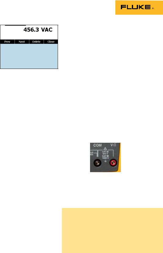
multimeter is rated at a minimum for CAT III 600V and preferably for CAT IV 600V/CAT III 1000V. The
category rating and voltage limit are typically found on the front panel of the multimeter right at the input terminals.
The new Fluke 289 DMM is dual rated CAT IV 600V and CAT III 1000V.
Refer to the ABC’s of DMM Safety from Fluke for additional information on category ratings and making safe measurements.
2 Fluke Corporation Multimeter measurements on variable frequency drives using the new Fluke 289 DMM
 Loading...