


92B/96B/99B/105B
ScopeMeter
Users Manual
4822 872 00724
March 1996, Rev. 4, 1/99
1996, 1999 Fluke Corporation. All rights reserved. Printed in the Netherlands All product names are trademarks of their respective companies.

I
TABLE OF CONTENTS
CHAPTER 1 INTRODUCING YOUR SCOPEMETER TEST TOOL
SCOPEMETER TEST TOOL FEATURES . . . . . . . . . . . . . . . . . . . . . . . . . . . . . . . . . . . . . . . . . . . . . . . 1-2 USING THE HOLSTER AND THE TILT STAND . . . . . . . . . . . . . . . . . . . . . . . . . . . . . . . . . . . . . . . . . . 1-3 POWERING THE SCOPEMETER TEST TOOL . . . . . . . . . . . . . . . . . . . . . . . . . . . . . . . . . . . . . . . . . . 1-4 MINIMIZING SIGNAL NOISE . . . . . . . . . . . . . . . . . . . . . . . . . . . . . . . . . . . . . . . . . . . . . . . . . . . . . . . . . 1-5 CHARGING THE BATTERY . . . . . . . . . . . . . . . . . . . . . . . . . . . . . . . . . . . . . . . . . . . . . . . . . . . . . . . . . 1-6 LOOKING AT ALL MEASUREMENT CONNECTIONS . . . . . . . . . . . . . . . . . . . . . . . . . . . . . . . . . . . . 1-7 READING THE DISPLAY . . . . . . . . . . . . . . . . . . . . . . . . . . . . . . . . . . . . . . . . . . . . . . . . . . . . . . . . . . . 1-8 USING THE KEYS . . . . . . . . . . . . . . . . . . . . . . . . . . . . . . . . . . . . . . . . . . . . . . . . . . . . . . . . . . . . . . . . 1-10 STEPPING THROUGH A WINDOW . . . . . . . . . . . . . . . . . . . . . . . . . . . . . . . . . . . . . . . . . . . . . . . . . . 1-12 USING ON-LINE INFORMATION . . . . . . . . . . . . . . . . . . . . . . . . . . . . . . . . . . . . . . . . . . . . . . . . . . . . 1-13
CHAPTER 2 GETTING STARTED
ADJUSTING THE DISPLAY . . . . . . . . . . . . . . . . . . . . . . . . . . . . . . . . . . . . . . . . . . . . . . . . . . . . . . . . . 2-3 SELECTING THE PROBE TYPE . . . . . . . . . . . . . . . . . . . . . . . . . . . . . . . . . . . . . . . . . . . . . . . . . . . . . . 2-4 POWER-ON CONFIGURATIONS . . . . . . . . . . . . . . . . . . . . . . . . . . . . . . . . . . . . . . . . . . . . . . . . . . . . . 2-4 PERFORMING AN EASY SETUP . . . . . . . . . . . . . . . . . . . . . . . . . . . . . . . . . . . . . . . . . . . . . . . . . . . . . 2-5
CHAPTER 3 MAKING MEASUREMENTS
MAKING CONNECTIONS . . . . . . . . . . . . . . . . . . . . . . . . . . . . . . . . . . . . . . . . . . . . . . . . . . . . . . . . . . . 3-2 USING THE MEASUREMENT FUNCTIONS . . . . . . . . . . . . . . . . . . . . . . . . . . . . . . . . . . . . . . . . . . . . . 3-3
USING A SHORTCUT TO MOST COMMONLY MEASUREMENTS . . . . . . . . . . . . . . . . . . . . . . . . . . 3-9
ORDERING MEASUREMENT READINGS . . . . . . . . . . . . . . . . . . . . . . . . . . . . . . . . . . . . . . . . . . . . . 3-10
MEASURING FUNCTIONS NOT AVAILABLE FROM THE MEASURE MENU . . . . . . . . . . . . . . . . . 3-10
MEASUREMENTS MAP . . . . . . . . . . . . . . . . . . . . . . . . . . . . . . . . . . . . . . . . . . . . . . . . . . . . . . . . . . . 3-12
II |
92B/96B/99B/105B Users Manual |
CHAPTER 4 USING THE DUAL DISPLAY MODE FUNCTIONS
MAKING CONNECTIONS . . . . . . . . . . . . . . . . . . . . . . . . . . . . . . . . . . . . . . . . . . . . . . . . . . . . . . . . . . . 4-2 SELECTING A MAIN MODE . . . . . . . . . . . . . . . . . . . . . . . . . . . . . . . . . . . . . . . . . . . . . . . . . . . . . . . . . 4-3 SELECTING RANGES (MANUAL/AUTO RANGE) . . . . . . . . . . . . . . . . . . . . . . . . . . . . . . . . . . . . . . . 4-7
HOLDING A STABLE MEASUREMENT (TOUCH HOLD ) . . . . . . . . . . . . . . . . . . . . . . . . . . . . . . . . . 4-8 DISPLAYING MINIMUM MAXIMUM READINGS WITH RELATED TRENDPLOT . . . . . . . . . . . . . . . 4-9
SELECTING THE SCOPEMETER KEY SUBMENU . . . . . . . . . . . . . . . . . . . . . . . . . . . . . . . . . . . . . . 4-13
MAKING MEASUREMENTS IN METER AND EXT.mV MODE . . . . . . . . . . . . . . . . . . . . . . . . . . . . . 4-14
TAKING RELATIVE READINGS (SCALING) . . . . . . . . . . . . . . . . . . . . . . . . . . . . . . . . . . . . . . . . . . . 4-14
CHAPTER 5 USING IN SCOPE MODE
MAKING CONNECTIONS . . . . . . . . . . . . . . . . . . . . . . . . . . . . . . . . . . . . . . . . . . . . . . . . . . . . . . . . . . |
. 5-3 |
MAKING AN EASY SETUP . . . . . . . . . . . . . . . . . . . . . . . . . . . . . . . . . . . . . . . . . . . . . . . . . . . . . . . . . . |
5-4 |
CONTROLLING INPUTS A AND B . . . . . . . . . . . . . . . . . . . . . . . . . . . . . . . . . . . . . . . . . . . . . . . . . . . . |
5-4 |
ADJUSTING THE AMPLITUDE . . . . . . . . . . . . . . . . . . . . . . . . . . . . . . . . . . . . . . . . . . . . . . . . . . . . . . |
5-5 |
ADJUSTING THE TIME BASE . . . . . . . . . . . . . . . . . . . . . . . . . . . . . . . . . . . . . . . . . . . . . . . . . . . . . . . |
5-6 |
POSITIONING THE WAVEFORM ON THE DISPLAY . . . . . . . . . . . . . . . . . . . . . . . . . . . . . . . . . . . . . |
5-7 |
ACQUIRING WAVEFORMS . . . . . . . . . . . . . . . . . . . . . . . . . . . . . . . . . . . . . . . . . . . . . . . . . . . . . . . . . |
5-8 |
SELECTING THE SCOPE SUBMENU . . . . . . . . . . . . . . . . . . . . . . . . . . . . . . . . . . . . . . . . . . . . . . . . |
5-10 |
TRIGGERING . . . . . . . . . . . . . . . . . . . . . . . . . . . . . . . . . . . . . . . . . . . . . . . . . . . . . . . . . . . . . . . . . . . |
5-12 |
USING THE MIN MAX ENVELOPE FUNCTION OF THE FLUKE 92B . . . . . . . . . . . . . . . . . . . . . . . |
5-21 |
USING THE SCOPE RECORD AND MIN MAX ENVELOPE FUNCTIONS OF |
|
THE FLUKE 96B, 99B, or 105B . . . . . . . . . . . . . . . . . . . . . . . . . . . . . . . . . . . . . . . . . . . . . . . . . . . . . |
5-22 |
MAKING COMBINATIONS WITH INPUT A AND INPUT B . . . . . . . . . . . . . . . . . . . . . . . . . . . . . . . . |
5-26 |
DISPLAYING MULTIPLE WAVEFORMS . . . . . . . . . . . . . . . . . . . . . . . . . . . . . . . . . . . . . . . . . . . . . . |
5-26 |
ADAPTING THE DISPLAY . . . . . . . . . . . . . . . . . . . . . . . . . . . . . . . . . . . . . . . . . . . . . . . . . . . . . . . . . |
5-27 |

III
CHAPTER 6 USING ADDITIONAL CAPABILITIES
MAKING MEASUREMENTS USING THE CURSORS . . . . . . . . . . . . . . . . . . . . . . . . . . . . . . . . . . . . . 6-2 DELETING MEMORIES . . . . . . . . . . . . . . . . . . . . . . . . . . . . . . . . . . . . . . . . . . . . . . . . . . . . . . . . . . . . . 6-6 SAVING TO MEMORY . . . . . . . . . . . . . . . . . . . . . . . . . . . . . . . . . . . . . . . . . . . . . . . . . . . . . . . . . . . . . . 6-7 RECALLING FROM MEMORY . . . . . . . . . . . . . . . . . . . . . . . . . . . . . . . . . . . . . . . . . . . . . . . . . . . . . . . 6-8 USING WAVEFORM MATH FUNCTIONS . . . . . . . . . . . . . . . . . . . . . . . . . . . . . . . . . . . . . . . . . . . . . 6-11 USING A PRINTER . . . . . . . . . . . . . . . . . . . . . . . . . . . . . . . . . . . . . . . . . . . . . . . . . . . . . . . . . . . . . . . 6-14 USING THE WAVEFORM GENERATOR . . . . . . . . . . . . . . . . . . . . . . . . . . . . . . . . . . . . . . . . . . . . . . 6-17 TESTING COMPONENTS . . . . . . . . . . . . . . . . . . . . . . . . . . . . . . . . . . . . . . . . . . . . . . . . . . . . . . . . . . 6-17 SETTING THE DATE AND TIME . . . . . . . . . . . . . . . . . . . . . . . . . . . . . . . . . . . . . . . . . . . . . . . . . . . . . 6-19 CHANGING THE RESET CONFIGURATIONS . . . . . . . . . . . . . . . . . . . . . . . . . . . . . . . . . . . . . . . . . . 6-20
ALTERING THE CONTINUOUS AUTO SET CONFIGURATION . . . . . . . . . . . . . . . . . . . . . . . . . . . . 6-22
CHAPTER 7 MEASURING EXAMPLES
MEASURING TEMPERATURE . . . . . . . . . . . . . . . . . . . . . . . . . . . . . . . . . . . . . . . . . . . . . . . . . . . . . . . 7-2 MEASURING CURRENT . . . . . . . . . . . . . . . . . . . . . . . . . . . . . . . . . . . . . . . . . . . . . . . . . . . . . . . . . . . . 7-4 MEASURING POWER WITH MATH FUNCTION . . . . . . . . . . . . . . . . . . . . . . . . . . . . . . . . . . . . . . . . . 7-7 MEASURING THREE-PHASE ON A DUAL INPUT . . . . . . . . . . . . . . . . . . . . . . . . . . . . . . . . . . . . . . . 7-9 MEASURING PHASE USING THE CURSORS . . . . . . . . . . . . . . . . . . . . . . . . . . . . . . . . . . . . . . . . . . 7-12 MEASURING PULSE RESPONSE OF AN AMPLIFIER . . . . . . . . . . . . . . . . . . . . . . . . . . . . . . . . . . . 7-14
CHAPTER 8 USER MAINTENANCE
CLEANING . . . . . . . . . . . . . . . . . . . . . . . . . . . . . . . . . . . . . . . . . . . . . . . . . . . . . . . . . . . . . . . . . . . . . . . 8-2 KEEPING BATTERIES IN OPTIMAL CONDITION . . . . . . . . . . . . . . . . . . . . . . . . . . . . . . . . . . . . . . . . 8-2 REPLACING AND DISPOSING OF BATTERIES . . . . . . . . . . . . . . . . . . . . . . . . . . . . . . . . . . . . . . . . . 8-3 REPLACING FUSES . . . . . . . . . . . . . . . . . . . . . . . . . . . . . . . . . . . . . . . . . . . . . . . . . . . . . . . . . . . . . . . 8-5 CALIBRATING THE PROBES . . . . . . . . . . . . . . . . . . . . . . . . . . . . . . . . . . . . . . . . . . . . . . . . . . . . . . . 8-5

IV 92B/96B/99B/105B Users Manual
CHAPTER 9 APPENDIXES
APPENDIX 9A SPECIFICATIONS . . . . . . . . . . . . . . . . . . . . . . . . . . . . . . . . . . . . . . . . . . . . . . . . . . . |
. 9-3 |
|
APPENDIX 9B |
PARTS AND ACCESSORIES . . . . . . . . . . . . . . . . . . . . . . . . . . . . . . . . . . . . . . . . . . |
9-15 |
APPENDIX 9C |
PM8907 INFORMATION . . . . . . . . . . . . . . . . . . . . . . . . . . . . . . . . . . . . . . . . . . . . . . |
9-19 |
APPENDIX 9D |
WARRANTY AND SERVICE CENTERS . . . . . . . . . . . . . . . . . . . . . . . . . . . . . . . . . . |
9-21 |
APPENDIX 9E TERMINOLOGY . . . . . . . . . . . . . . . . . . . . . . . . . . . . . . . . . . . . . . . . . . . . . . . . . . . . . |
9-23 |
|

V
VI |
92B/96B/99B/105B Users Manual |
ABOUT THIS MANUAL
Chapter 1 Introducing the ScopeMeter Test Tool
This chapter introduces features and capabilities of your ScopeMeter test tool.
Chapter 2 Getting Started
This chapter provides a 15-minute demonstration intended for those who are not familiar with the ScopeMeter test tool.
Chapter 3 Making Measurements
This chapter explores all measurements and specifies the use of the direct Measure Menu key. At any time, you can choose over 30 measurements to get an immediate reading on the display.
Chapter 4 Using the Dual Display Mode
This chapter addresses the use of four Dual Display Mode Functions of the ScopeMeter test tool:  ,
,  ,
,  , and
, and  . You will learn how to set up the test tool for ac and dc voltage measurements, diode tests, resistance measurements, and trend plotting. Chapter 5 contains all the Scope mode information.
Chapter 5 Using the Scope Mode
This chapter explores the specific use of the test tool as a digital storage oscilloscope. You will learn how to make, store, and compare measurements.
Chapter 6 Using Additional Capabilities
This chapter explores the additional capabilities available with your ScopeMeter test tool. The chapter covers subjects, such as Scope measurements using the cursors, saving and recalling screens, waveforms, or setups, and making a hard copy on your printer.
Chapter 7 Measuring Examples
This chapter outlines step-by-step procedures necessary to make some typical measurements.
Chapter 8 User Maintenance
This chapter describes the cleaning of the ScopeMeter test tool and proper use and replacement of the battery pack. Periodic probe calibration is also covered here.
Chapter 9 Appendixes
A.Specifications: Operating characteristics.
B.Parts and Accessories: Model numbers and replacement codes for all parts and accessories delivered with your ScopeMeter test tool.
C.PM8907 Power Adapter/ Battery Charger.
D.Warranty Information and Service Centers: Warranty terms and Service Center addresses.
E.Terminology: Glossary of special terms.

VII
Index
The index at the end of the manual lists words alphabetically. Consult this list to find an item quickly.
NOTE
Throughout this manual an  through a model number (92B) indicates that the function being discussed does not apply to that specific model number.
UNPACKING THE SCOPEMETER TEST TOOL KIT
The following items should be included in your ScopeMeter® test tool kit (also see the yellow shipment card):
1.ScopeMeter test tool
2.NiCad Battery Pack (installed)
3.Protective Holster
4.Users Manual (this book)
5.Accessory Case, which includes the following:
6.Set of two Probes
7.Set of two Industrial Alligator Clips for Scope Probes
8.Multimeter Test Lead Set, which includes the following:
9.Test Leads (red and black)
10.Industrial Test Probes (red and black)
11.Industrial Alligator Clip (black)
12.Banana Adapters (red and black)
13.Power Adapter/Battery Charger
14.Probe Accessory Set, which includes the following:
15.HF Adapters (2 x black)
16.Mini Test Hooks (red and grey)
17.Trim Screwdrivers (red and grey)
18.Probe Tip to Banana Adapters (red and grey)
19.Hight Voltage Test Pins (red and grey)
20 FlukeView Software with RS-232 Adapter/Cable for communication with a computer 92B 96B 99B.

VIII |
92B/96B/99B/105B Users Manual |
WARNING
READ "SAFETY" CAREFULLY BEFORE USING YOUR SCOPEMETER TEST TOOL.
SAFETY
The instrument described in this manual is designed to be used only by qualified personnel.
Safety Precautions
To use this instrument safely, it is essential that operating and servicing personnel follow both generally accepted safety procedures and the safety precautions specified in this manual.
Specific warning and caution statements, where they apply, will be found throughout the manual.
Where necessary, the warning and caution statements and/or symbols are marked on the instrument.
A CAUTION identifies conditions and actions that may damage the test tool.
A WARNING IDENTIFIES CONDITIONS AND ACTIONS THAT POSE HAZARD(S) TO THE USER.
International electrical symbols used are explained below.
Caution (see explanation in |
DOUBLE INSULATION |
manual) |
(Protection Class) |
Common (Lo) input symbol, |
Recycling symbol |
equal potential |
|
High BNC input symbol |
DC-Direct Current |
Earth |
AC-Alternating Current |
The terms "Isolated" or "Electrically floating" are used in this manual to indicate a measurement in which the ScopeMeter test tool COM (common, also called ground) is connected to a voltage different from earth ground. The term "Grounded" is used in this manual to indicate a measurement in which the ScopeMeter test tool COM (common) is connected to an earth ground potential.
The ScopeMeter test tool COM (common) inputs (red INPUT A BNC shield, grey INPUT B BNC shield, and black 4-mm banana jack) are connected internally via selfrecovering fault protection. The input connectors have no exposed metal and are fully insulated to protect against electrical shock. The black 4-mm banana jack COM (common) can be connected to a voltage above earth ground for isolated (electrically floating) measurements and is rated up to 600V rms above earth ground.
IX
The ScopeMeter test tool uses a three-lead connection system for dual input, isolated (electrically floating) measurements. The connections for isolated and grounded measurements are shown in the following illustration.
Figure 1. Common (Ground) Connections |
 WARNING
DO THE FOLLOWING TO AVOID ELECTRICAL SHOCK IF A SCOPEMETER TEST TOOL  COM (COMMON) INPUT IS CONNECTED TO >42V PEAK (30V RMS):
1.USE ONLY THE TEST LEAD/PROBE SET SUPPLIED WITH THE SCOPEMETER TEST TOOL (OR SAFETY-DESIGNED EQUIVALENTS WITHOUT EXPOSED METAL CONNECTORS).
2.DO NOT USE CONVENTIONAL EXPOSED METAL BNC OR BANANA PLUG CONNECTORS IF THE  COM (COMMON) IS >42V PEAK (30V RMS).
3.USE ONLY ONE  COM (COMMON) CONNECTION (THE 4-MM BLACK BANANA JACK).
4.REMOVE ALL PROBES AND TEST LEADS THAT ARE NOT IN USE.
5.USE 600V RATED PROBE TIP ADAPTERS. "600V" IS PRINTED ON EQUIPMENT SO RATED.
6.CONNECT THE PM8907 POWER ADAPTER TO THE AC OUTLET BEFORE CONNECTION TO THE SCOPEMETER TEST TOOL.
X |
92B/96B/99B/105B Users Manual |
If Safety-Protection is Impaired
Use of equipment in a manner not specified may impair the protection provided by the equipment. Before use, inspect probes for mechanical damage and replace damaged probes!
Whenever it is likely that safety has been impaired, the instrument must be turned off and disconnected from line power. The matter should then be referred to qualified personnel. Safety is likely to be impaired if, for example, the instrument fails to perform the intended measurements or shows visible damage.
MAKING ISOLATED MEASUREMENTS
Isolating from Earth Ground
The ScopeMeter test tool uses a three-lead connection system for dual input, isolated (electrically floating) measurements. Use a test lead connected to the black 4-mm banana jack as common ground.
There are only three wires to connect for dual input isolated ground operation, useful for three-phase industrial voltage measurements. You can connect the three leads on the test tool (INPUT A, INPUT B, and common) to a threephase electrical power line in any order. Use the A-B mode (see Chapter 5) to display all three phases of electrical power at the same time.
For three-phase electrical or other isolated ground industrial measurements, we strongly recommend that you use the black Industrial Alligator Clip and the red and grey Industrial Probe Alligator Clips (see Figure 4). These parts are included with original purchase ScopeMeter test tools and are also available as accessories from your FLUKE representative.
Isolating from Input to Input
The ScopeMeter test tool is not isolated between inputs but uses the black 4-mm banana jack for measurements isolated from earth ground.
Complete isolation between INPUT A and INPUT B is useful for some floating measurement applications, such as measuring different isolated transformer windings at the same time.
For those applications requiring true isolated grounds (commons) between inputs, we recommend that you make two separate measurements or use two ScopeMeter test tools.

XI
DECLARATION OF CONFORMITY for
FLUKE 92B/96B/99B/105B
ScopeMeter® Series II Test Tool
Manufacturer
Fluke Industrial B.V.
Lelyweg 1
7602 EA Almelo
The Netherlands
Statement of Conformity
Based on test results using appropriate standards, the product is in conformity with
Electromagnetic Compatibility Directive 89/336/EEC Low Voltage Directive 73/23/EEC
Sample tests
Standards used:
EN 61010-1 (1993)
Safety Requirements for Electrical Equipment for Measurement, Control, and Laboratory Use
EN 50081-1 (1992)
Electromagnetic Compatibility Generic Emission Standard:
EN55022 and EN60555-2
EN 50082-1 (1992)
Electromagnetic Compatibility Generic Immunity Standard:
IEC801-2, -3, -4, -5
The tests have been performed in a typical configuration.
This Conformity is indicated by the symbol 
 , i.e. 'Conformité européenne'.

XII |
92B/96B/99B/105B Users Manual |
Single Input Connection |
Single Input Connection |
with Mini Test Hook |
with HF Adapter |
Dual Input Connections |
Dual Input Connections |
with Mini Test Hooks |
with HF Adapters |
Figure 2. Input Connections for High Frequency Electronic Measurement
WARNING
To prevent electric shock and personal injury, Mini Test Hooks and HF Adapters must not be connected to any voltage higher than 42V peak (30V rms) to earth. Always pay attention to the markings on the accessories.

XIII
Single Input Connection
with High Voltage
Test Pin
Single Input Connection
with High Voltage
Test Pin & AC20
Single Input Connection with Industrial Alligator Clips (PM9084/001 & AC20)
Dual Input Connections with Industrial Alligator Clips (PM9084/001 & AC20)
Figure 3. Input Connections for Isolated Heavy Duty Industrial Measurements
XIV |
92B/96B/99B/105B Users Manual |

Chapter 1
Introducing your ScopeMeter Test Tool
SCOPEMETER TEST TOOL FEATURES . . . . . . . . . 1-2
ScopeMeter Features . . . . . . . . . . . . . . . . . . . . . . . 1-2
Scope Capabilities . . . . . . . . . . . . . . . . . . . . . . . . . 1-2
Digital MultiMeter Capabilities . . . . . . . . . . . . . . . . 1-2
USING THE HOLSTER AND THE TILT STAND . . . . 1-3
POWERING THE SCOPEMETER TEST TOOL . . . . . 1-4
MINIMIZING SIGNAL NOISE . . . . . . . . . . . . . . . . . . . 1-5
CHARGING THE BATTERY . . . . . . . . . . . . . . . . . . . . 1-6
Saving Battery Life . . . . . . . . . . . . . . . . . . . . . . . . . 1-6
LOOKING AT ALL
MEASUREMENT CONNECTIONS . . . . . . . . . . . . . . . 1-7
Common Ground, Inputs A B . . . . . . . . . . . . . . . . . 1-7
Input/Output Terminal Ratings . . . . . . . . . . . . . . . . 1-7
RS-232 Optical Interface Connection . . . . . . . . . . . 1-8
READING THE DISPLAY . . . . . . . . . . . . . . . . . . . . . 1-8 Reading a Dual Display . . . . . . . . . . . . . . . . . . . . . 1-9 Reading a Scope Display . . . . . . . . . . . . . . . . . . . 1-9 Reading a Window Display . . . . . . . . . . . . . . . . . . 1-9 USING THE KEYS . . . . . . . . . . . . . . . . . . . . . . . . . . 1-10
STEPPING THROUGH A WINDOW . . . . . . . . . . . . 1-12 USING ON-LINE INFORMATION . . . . . . . . . . . . . . 1-13

1 - 2 |
92B/96B/99B/105B Users Manual |
SCOPEMETER TEST TOOL FEATURES
Your ScopeMeter test tool combines the capabilities of an easy-to-use digital storage oscilloscope with the versatility of a digital multimeter. When you select a measurement function, the test tool automatically chooses the best setup to analyze and compare complex waveforms, or simply to read voltage levels.
ScopeMeter Features
•Rugged, dual-input oscilloscope and high bandwidth true RMS Meter in one instrument.
•Four hours of battery operation.
•Allows you to measure floating from mains with the 600V insulated probes.
•Optically isolated PC/Printer interface.
•Information key to access on line information on all functions.
•Separate memories for storage of waveforms, instrument setups, and screens.
Scope Capabilities
•Triggering includes external triggering and TV line selector.
•Five giga samples in recurrent mode for full resolution display of high frequency signals. (2.5 giga samples for Fluke 92B and 96B)
•Continuous Auto Set for hands-free probing without adjustments to test the tool.
•MIN MAX Envelope mode for recording changes in waveforms.
•ScopeRecord™ allows you to capture and view waveforms spanning 120 screens 92B .
Digital MultiMeter Capabilities
•3000 count, 5 MHz bandwidth true RMS.
•Each Meter reading is accompanied by a Scope display.
•Displays up to four simultaneous readings.
•MIN MAX TrendPlot automatically graphs meter readings and shows minimum and maximum peak values with the actual or relative time.

Introducing The ScopeMeter Test Tool |
1 - 3 |
USING THE HOLSTER AND THE TILT STAND |
|
The ScopeMeter test tool is cradled in a holster that provides |
RELEASE |
shock protection during rough handling. All keys and |
HERE |
connections are accessible with the holster in place. You will |
|
need to remove the holster only to replace the batteries. |
|
(See Chapter 8 for battery replacement instructions.) |
|
The test tool is also equipped with a multiposition tilt stand, |
|
allowing viewing from different angles. The stand can also |
|
be used to hang the test tool at a convenient viewing |
|
position. Simply push up on the quick release and tilt the |
|
stand. The tilt stand/bracket is fully usable with the holster |
|
in place. Typical positions are shown in Figure 1-1. |
|
Figure 1-1. Multiposition Stand

1 - 4 |
92B/96B/99B/105B Users Manual |
POWERING THE SCOPEMETER TEST TOOL
The test tool can be powered from any of the following sources. Refer to Figure 1-2.
•Internal Battery Pack (PM9086)
A rechargeable NiCad Battery Pack comes installed in every test tool.
•C Cell Batteries
You can use four alkaline batteries in place of the NiCad Battery Pack. (The charger is defeated when standard C cells are installed).
•Power Adapter (PM8907)
The Power Adapter/Battery Charger powers the test tool from a standard ac outlet. The test tool can be used during battery charging. Verify that your local line voltage is appropriate before using the Power Adapter/Battery Charger to power the test tool and/or charge the battery pack.
See Appendix 9C for more information.
•Automotive Adapter (PM9087, optional)
The Automotive Adapter powers and charges from a standard 12V dc automotive accessory (lighter) outlet.
Refer to Chapter 8 for battery replacement instructions.
EXTERNAL
POWER
SOCKET
Figure 1-2. Power Connections
NOTE
If the test tool is powered with the Power Adapter but doesn’t work, the batteries may be completely empty. In that case it is advised to charge the batteries for 21 hours before using the test tool.
Introducing The ScopeMeter Test Tool |
1 - 5 |
MINIMIZING SIGNAL NOISE
In general, using your test tool on battery power only will minimize noise pickup. Using the 10:1 probe will help in noise rejection.
If you use the Power Adapter (PM8907), connect a test lead from the black 4-mm banana jack COM (common) to the measurement common (ground) of the system under test. This technique reduces or eliminates any power line related noise.

1 - 6 |
92B/96B/99B/105B Users Manual |
CHARGING THE BATTERY
WARNING
TO AVOID ELECTRICAL SHOCK, USE ONLY A BATTERY CHARGER THAT IS AUTHORIZED FOR USE WITH SCOPEMETER TEST TOOL.
Use the following procedure to charge the battery pack and power the instrument:
1.Connect the Power Adapter/Battery Charger to line voltage.
2.Insert the Power Adapter/Battery Charger low voltage plug into the Power Adapter connector of the ScopeMeter test tool. The test tool can now be used while the NiCad batteries charge slowly. If the test tool is turned off, the batteries charge more quickly.
NOTE
When the batteries are completely empty, the test tool can not work during charging. In that case it is advised to charge the batteries for 21 hours before using the test tool.
During operation, when the batteries are low, a blinking battery symbol  appears on the top right of the display. When this occurs there is typically more than 30 minutes of operating time left.
3.The Power Adapter/Battery Charger uses a trickle charge for the batteries, so no damage can occur if you leave it charging for long periods, e.g., through the weekend. Typically a 21-hour recharge provides 4 hours of use.
Saving Battery Life
When operated only on batteries, the test tool conserves power by shutting itself down. If no new keys have been pressed for 6 minutes or if the battery level is too low, the test tool beeps and displays a message. This prompts you to turn off the test tool or to continue. If no key is pressed during the next 5 minutes, the test tool turns itself off automatically.
When the  is pressed ON, the last configuration prior to the automatic shutdown will be restored.
Automatic power shutdown will not occur if Min Max TrendPlot™ or ScopeRecord™ is active or if any key is pressed. Although recording will continue if the batteries are low, memory retention is not jeopardized.
If the Power Adapter is connected, there is no automatic power shutdown.

Introducing The ScopeMeter Test Tool |
1 - 7 |
LOOKING AT ALL
MEASUREMENT CONNECTIONS
The ScopeMeter test tool provides four signal connection points: two safety BNC jack inputs (red INPUT A and grey INPUT B) and two safety 4-mm banana jack inputs (COM and Ω  EXT.mV). This arrangement is shown in Figure 1-3. All connections are positioned within a protective recess at the top of the instrument. The banana jacks are also used as Waveform Generator Output. 92B 96B
Figure 1-3. Measurement Connections
In  mode, you can use the red INPUT A BNC jack and the grey INPUT B BNC jack as input.
In  mode, only the red INPUT A BNC jack is used as input.
In  ,
,  , and
, and  modes, use the red and black 4-mm banana jacks.
For low frequency measurements (up to about 2 MHz), ground can be connected to the black 4-mm banana jack. For higher frequencies you must use the HF Adapter or Mini Testhook on the probe.
The red 4-mm banana jack also serves as an input connection for an external trigger in Scope mode or as an output connection for the waveform generator. This waveform generator can provide voltage or current output.
Common Ground, Inputs A B
The test tool uses a three-lead connection system for dual input, isolated (electrically floating) measurements.
Input/Output Terminal Ratings
Maximum voltage ratings are defined near the related terminal. Refer to the Specifications in Appendix 10A for complete terminal rating information.

1 - 8 |
92B/96B/99B/105B Users Manual |
RS-232 Optical Interface Connection
The Optically Isolated RS-232 Adapter/Cable (PM9080) can be connected to the test tool for printer output and computer interface. Using the FlukeView software for DOS and Windows adds the following functionality to your ScopeMeter test tool:
•Storing of measurements in memory for later retrieval.
•Comparing of measurements with reference examples.
•Storing, analyzing, and documenting measurements.
The following table shows the printing and communication features for each model:
92B 96B 99B 105B
Screen dump using FlukeView
Direct output to printer
Remote control via computer software
READING THE DISPLAY
The display provides a great deal of information. The major part of the display is always devoted to meter readings or the scope waveform. A Dual display appears in  ,
,  ,
,  , and
, and  modes, and is divided into two areas: Main display and Bottom display. A Scope display appears in
  mode, and is divided into three areas: Top display, Main display, and Bottom display.
Refer to Figure 1-4 during the following discussions.
Figure 1-4. ScopeMeter Test Tool Display
Introducing The ScopeMeter Test Tool |
1 - 9 |
Reading a Dual Display
Main Display: Displays the numeric readings combined with a full screen-width waveform display.
Bottom Display: Displays the menu that provides choices available through the function keys and shows which are active.
Reading a Scope Display
Top Display: Identifies the voltage range, type of signal coupling, selected probe type for INPUT A and INPUT B, time scale, trigger source, and trigger slope. The top right area displays the present status of the test tool, AUTO, MANUAL, RUN, HOLD, etc.
Main Display: Displays the actual or stored waveforms (Scope mode).
Bottom Display: Displays the menu that provides choices available through the function keys and shows which are active.
Reading a Window Display
When you change a setup, a part of the Main display area is used for a window. It displays choices accessed with the related function key from which you make a selection by pressing  (SELECT ITEM). The waveform area is compressed to about 50% (amplitude) size, and the window replaces the bottom half of the Main display.
1 - 10 |
92B/96B/99B/105B Users Manual |
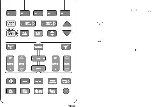
USING THE KEYS
The keys with a predefined function, regardless of the test tool's mode, are called keys or hard keys. Usally they give access to a menu, where items can be selected.
The two yellow keys  and
and  provide the possible ways to find your measurement.
 gives immediate access to a list of measurements. When you choose a measurement, the test tool automatically selects the related main mode.
 gives access to the Main menu. Here you can choose from the five main modes:
  ,
,  ,
,  ,
,  , and
, and  . Pressing
  gives you more control over the selected main mode.
Figure 1-5. The Keypad
Introducing The ScopeMeter Test Tool |
1 - 11 |
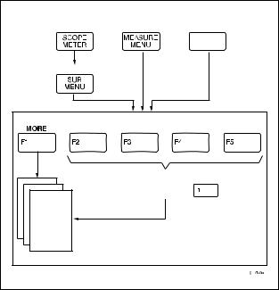
Figure 1-6 shows the basic navigation of the test tool.
Yellow |
Yellow |
Dark grey |
|
|
Hard key |
Dark grey |
|
|
|
SubMenu Structure |
|
|
Most common Functions |
|
|
also found under |
|
Figure 1-6. Basic Navigation |
||
The five blue keys  ,
,  ,
,  ,
,  , and
, and  are called function keys. These keys change function based on the present active menu. Actual function key definitions appear on the bottom display. Function keys and windows work together to provide a complete menu-driven user interface.
 is the MORE function key, which opens the window assigned to the key.
When you press the Submenu key for any main function, the  ,
,  ,
,  , and
, and  keys allow immediate access to the more common functions that are also under the
  (MORE function key).
The 
 keys are used to choose an item in a box, or directly from the window. These keys are indicated by two arrows.

1 - 12 |
92B/96B/99B/105B Users Manual |
STEPPING THROUGH A WINDOW
When a window appears, the assignments to the function keys change as follows:
 is the 'CLOSE' key, which closes the active window.
 is the 'CANCEL' key, which ignores changed selections and closes the active window.
 is the 'SELECT ITEM' key, which opens and closes a list box and selects the highlighted item.
Stepping through a window has a fixed sequence as shown in Figure 1-7.
Figure 1-7. Sequence to Go Through a Window
The fixed sequence is as follows:
1.  Press a MORE function key. This opens a window.
(Press  (NEXT PAGE) or
  (PREVIOUS PAGE) to choose an item on page 2 or page 3.)
2. or
or  Choose the item that has to be changed.
3. Open the list box.
4. or
or  Choose the new parameter.
5. This selects the new parameter and closes the list box.
Repeat steps 2 through 5 for more items.
6.  Close the window and continue measurements.

Introducing The ScopeMeter Test Tool |
1 - 13 |
USING ON-LINE INFORMATION
You can get information about functions at any time by pressing  . The short descriptions will help you understand how the test tool functions.
When you operate the ScopeMeter test tool, the display provides information about the present condition or explains procedures taking place and asks for confirmation. These messages are always displayed in a box.
More information is available by pressing  . This displays one or more pages of extended on-line information. More information is available under the following conditions:
-In a menu (F1 to F5) you always can get information on the functions for every function key.
-In a window you can get more information about the highlighted function when the  icon is displayed.
-In a message you can get more information about the conflict with the present setup when the  icon is displayed. If necessary, the test tool asks for confirmation and disables the conflicting situation.
Figure 1-8 hows an example of a "function info" screen.
You can set the information level for on-line information to high or low. This is explained in Chapter 6.
Figure 1-8. Using On-Line Information
•When you have read the displayed information, press
 to exit the information mode.
This returns the test tool to the latest setup before you pressed  , and you can continue your measurement.
1 - 14 |
92B/96B/99B/105B Users Manual |
 Loading...