


Stylus Photo RX520
Table of contents
 Loading...
Epson Stylus Photo RX520, Stylus Photo RX530, Stylus Photo CX7700, Stylus Photo CX7800 Service Manual. Parts List
EPSON Stylus Photo RX520/RX530
Stylus CX7700/CX7800
Color Inkjet Printer
SEIJ05-015
SERVICE MANUAL

Notice:
All rights reserved. No part of this manual may be reproduced, stored in a retrieval system, or transmitted in any form or by any means, electronic, mechanical,
photocopying, recording, or otherwise, without the prior written permission of SEIKO EPSON CORPORATION.
The contents of this manual are subject to change without notice.
All effort have been made to ensure the accuracy of the contents of this manual. However, should any errors be detected, SEIKO EPSON would greatly appreciate being
informed of them.
The above not withstanding SEIKO EPSON CORPORATION can assume no responsibility for any errors in this manual or the consequences thereof.
EPSON is a registered trademark of SEIKO EPSON CORPORATION.
General Notice: Other product names used herein are for identification purpose only and may be trademarks or registered trademarks of their
respective owners. EPSON disclaims any and all rights in those marks.
Copyright © 2005 SEIKO EPSON CORPORATION.
I&I CS/Quality Management & PL Department

PRECAUTIONS
Precautionary notations throughout the text are categorized relative to 1)Personal injury and 2) damage to equipment.
DANGER Signals a precaution which, if ignored, could result in serious or fatal personal injury. Great caution should be exercised in performing procedures
preceded by DANGER Headings.
WARNING Signals a precaution which, if ignored, could result in damage to equipment.
The precautionary measures itemized below should always be observed when performing repair/maintenance procedures.
DANGER
1. ALWAYS DISCONNECT THE PRODUCT FROM THE POWER SOURCE AND PERIPHERAL DEVICES PERFORMING ANY MAINTENANCE OR REPAIR
PROCEDURES.
2. NO WORK SHOULD BE PERFORMED ON THE UNIT BY PERSONS UNFAMILIAR WITH BASIC SAFETY MEASURES AS DICTATED FOR ALL
ELECTRONICS TECHNICIANS IN THEIR LINE OF WORK.
3. WHEN PERFORMING TESTING AS DICTATED WITHIN THIS MANUAL, DO NOT CONNECT THE UNIT TO A POWER SOURCE UNTIL INSTRUCTED TO
DO SO. WHEN THE POWER SUPPLY CABLE MUST BE CONNECTED, USE EXTREME CAUTION IN WORKING ON POWER SUPPLY AND OTHER
ELECTRONIC COMPONENTS.
4. WHEN DISASSEMBLING OR ASSEMBLING A PRODUCT, MAKE SURE TO WEAR GLOVES TO AVOID INJURIER FROM METAL PARTS WITH SHARP
EDGES.
WARNING
1. REPAIRS ON EPSON PRODUCT SHOULD BE PERFORMED ONLY BY AN EPSON CERTIFIED REPAIR TECHNICIAN.
2. MAKE CERTAIN THAT THE SOURCE VOLTAGES IS THE SAME AS THE RATED VOLTAGE, LISTED ON THE SERIAL NUMBER/RATING PLATE. IF THE
EPSON PRODUCT HAS A PRIMARY AC RATING DIFFERENT FROM AVAILABLE POWER SOURCE, DO NOT CONNECT IT TO THE POWER SOURCE.
3. ALWAYS VERIFY THAT THE EPSON PRODUCT HAS BEEN DISCONNECTED FROM THE POWER SOURCE BEFORE REMOVING OR REPLACING
PRINTED CIRCUIT BOARDS AND/OR INDIVIDUAL CHIPS.
4. IN ORDER TO PROTECT SENSITIVE MICROPROCESSORS AND CIRCUITRY, USE STATIC DISCHARGE EQUIPMENT, SUCH AS ANTI-STATIC WRIST
STRAPS, WHEN ACCESSING INTERNAL COMPONENTS.
5. REPLACE MALFUNCTIONING COMPONENTS ONLY WITH THOSE COMPONENTS BY THE MANUFACTURE; INTRODUCTION OF SECOND-SOURCE
ICs OR OTHER NON-APPROVED COMPONENTS MAY DAMAGE THE PRODUCT AND VOID ANY APPLICABLE EPSON WARRANTY.
6. WHEN USING COMPRESSED AIR PRODUCTS; SUCH AS AIR DUSTER, FOR CLEANING DURING REPAIR AND MAINTENANCE, THE USE OF SUCH
PRODUCTS CONTAINING FLAMMABLE GAS IS PROHIBITED.
About This Manual
This manual describes basic functions, theory of electrical and mechanical operations, maintenance and repair procedures of the printer. The instructions and procedures included
herein are intended for the experienced repair technicians, and attention should be given to the precautions on the preceding page.
Manual Configuration
This manual consists of six chapters and Appendix.
CHAPTER 1. PRODUCT DESCRIPTIONS
Provides a general overview and specifications of the product.
CHAPTER 2. OPERATING PRINCIPLES
Describes the theory of electrical and mechanical operations of the
product.
CHAPTER 3. TROUBLESHOOTING
Describes the step-by-step procedures for the troubleshooting.
CHAPTER 4. DISASSEMBLY / ASSEMBLY
Describes the step-by-step procedures for disassembling and
assembling the product.
CHAPTER 5. ADJUSTMENT
Provides Epson-approved methods for adjustment.
CHAPTER 6. MAINTENANCE
Provides preventive maintenance procedures and the lists of Epson-
approved lubricants and adhesives required for servicing the product.
CHAPTER 7. APPENDIX
Provides the following additional information for reference:
• Connector Summary
• Exploded Diagram
• Parts List
• Electrical Circuits
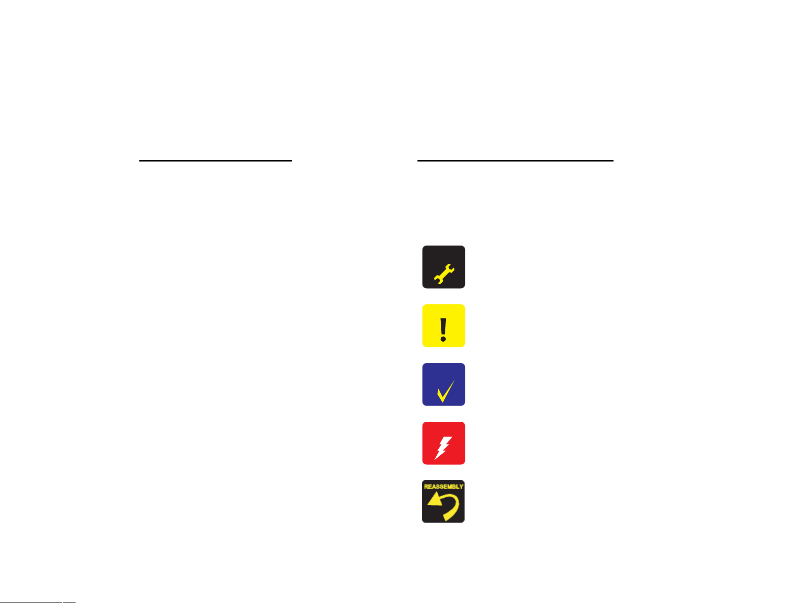
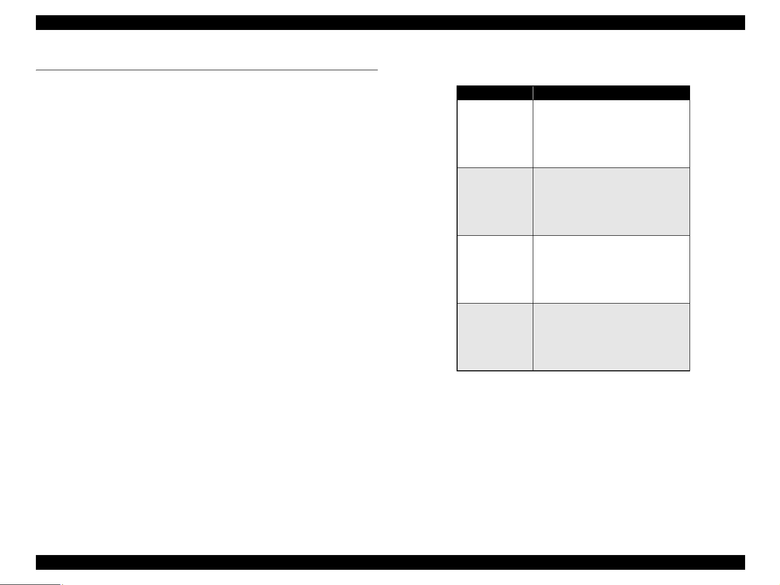
Symbols Used in this Manual
Various symbols are used throughout this manual either to provide additional
information on a specific topic or to warn of possible danger present during a
procedure or an action. Be aware of all symbols when they are used, and always read
NOTE, CAUTION, or WARNING messages.
Indicates an operating or maintenance procedure, practice or condition
that, if not strictly observed, could result in injury or loss of life.
Indicates an operating or maintenance procedure, practice, or condition
that, if not strictly observed, could result in damage to, or destruction of,
equipment.
May indicate an operating or maintenance procedure, practice or
condition that is necessary to accomplish a task efficiently. It may also
provide additional information that is related to a specific subject, or
comment on the results achieved through a previous action.
Indicates an operating or maintenance procedure, practice or condition
that, if not strictly observed, could result in injury or loss of life.
Indicates that a particular task must be carried out according to a certain
standard after disassembly and before re-assembly, otherwise the quality
of the components in question may be adversely affected.
A D J U S T M E N T
R E Q U I R E D
C A U T I O N
C H E C K
P O I N T
W A R N I N G

Revision Status
Revision Issued Date Description
A August 26, 2005 First Release
B September 22, 2005 CHAPTER 5 ADJUSTMENT
• full-fledged revision
C December 9, 2005 CHAPTER 5 ADJUSTMENT
• “5.3.2 Original Adjustment” on page 209. Correction to reflect the new release of the adjustment program.
D May 10, 2006 CHAPTER 1 PRODUCT DESCRIPTION
• “1.4.1.1 Supported Paper Sizes, Types and Qualities” on page 27. Error is corrected.
CHAPTER 4 DISASSEMBLY / ASSEMBLY
• “4.4.14 Holder Shaft Unit” on page 165. The removal procedure is modified.

EPSON Stylus Photo RX520/RX530 / Stylus CX7700/CX7800 Revision D
6
CONTENTS
Chapter 1 PRODUCT DESCRIPTION
1.1 Overview ............................................................................................................. 10
1.1.1 Features....................................................................................................... 10
1.2 Specifications ...................................................................................................... 12
1.2.1 Printer Specifications.................................................................................. 12
1.2.2 Scanner Specifications................................................................................ 20
1.2.3 Common ..................................................................................................... 22
1.2.4 Black Ink Save Mode (Only for Stylus CX7700/CX7800)........................ 23
1.3 Interface............................................................................................................... 24
1.3.1 USB Interface ............................................................................................. 24
1.3.2 Standard Card Slots .................................................................................... 25
1.3.3 Multi-slot Operations.................................................................................. 26
1.4 Stand-alone Copy ................................................................................................ 27
1.4.1 Basic Specifications.................................................................................... 27
1.4.2 Copy Speed (TBD) ..................................................................................... 29
1.4.3 Configuration for Copying ......................................................................... 29
1.4.4 Relation between original and copy ........................................................... 30
1.5 Memory Card Print.............................................................................................. 33
1.5.1 Basic Specifications.................................................................................... 33
1.5.2 Functions..................................................................................................... 35
1.5.3 Index Sheet ................................................................................................. 37
1.5.4 Layout and Paper Type, Paper Size............................................................ 40
1.5.5 Options........................................................................................................ 40
1.5.6 Trimming Function..................................................................................... 41
1.5.7 Assignment Rules for Photo Frame Numbers and Rotation....................... 41
1.5.8 Layout Drawings ........................................................................................ 43
1.5.9 Relation between Paper Type and Quality ................................................. 47
1.6 Film Mode ........................................................................................................... 48
1.6.1 Basic Specifications.................................................................................... 48
1.6.2 Original Film Setting Specification ............................................................ 48
1.6.3 Original Photo Setting Specification .......................................................... 49
1.6.4 Supported Paper Sizes, Types and Qualities .............................................. 50
1.7 Setting Mode ....................................................................................................... 52
1.7.1 Check Ink Levels ........................................................................................ 52
1.7.2 Clean Printhead........................................................................................... 52
1.7.3 Check Ink Nozzles...................................................................................... 52
1.7.4 Align Printhead........................................................................................... 53
1.7.5 Change Cartridges ...................................................................................... 53
1.7.6 Auto Correct ............................................................................................... 54
1.7.7 Borderless Setting....................................................................................... 54
1.7.8 Copy Quality............................................................................................... 54
1.8 USB Direct-Print/PictBridge Functions .............................................................. 55
1.8.1 Supported Device ....................................................................................... 55
1.8.2 Functions Available from DSC .................................................................. 55
1.8.3 Operation .................................................................................................... 55
1.9 Control Panel....................................................................................................... 57
1.9.1 Buttons........................................................................................................ 57
1.9.2 Indicators .................................................................................................... 57
1.9.3 The Method of Changing Modes................................................................ 59
1.9.4 Operations................................................................................................... 60
1.9.5 Printer Condition and Panel Status............................................................. 66
1.9.6 Memory Functions (TBD).......................................................................... 70
1.9.7 Printer Initialization (TBD) ........................................................................ 71
Chapter 2 OPERATING PRINCIPLES
2.1 Overview ............................................................................................................. 73
2.2 Printer Mechanism .............................................................................................. 73
2.2.1 Printer Mechanism...................................................................................... 73
2.2.2 Printhead..................................................................................................... 74
2.2.3 Carriage Mechanism................................................................................... 76
2.2.4 Paper Loading/Feeding Mechanism ........................................................... 78
2.2.5 Ink System Mechanism .............................................................................. 83
2.2.6 Ink Sequence............................................................................................... 86
2.3 Scanner Mechanism ............................................................................................ 88
2.3.1 Scanner Carriage Mechanism..................................................................... 88
2.4 Electrical Circuit Operating Principles................................................................ 91
2.4.1 C610 PSB/PSE Board................................................................................. 92
2.4.2 C613 Main Board ....................................................................................... 93
2.5 Banding Reduction System ............................................................................... 100

EPSON Stylus Photo RX520/RX530 / Stylus CX7700/CX7800 Revision D
7
Chapter 3 TROUBLESHOOTING
3.1 Overview ........................................................................................................... 102
3.1.1 Specified Tools ......................................................................................... 102
3.1.2 Preliminary Checks................................................................................... 102
3.2 Troubleshooting................................................................................................. 103
3.2.1 Troubleshooting for Motors and Sensors ................................................. 103
3.2.2 Troubleshooting With LCD Error Indications.......................................... 104
3.2.3 Superficial Phenomenon-Based Troubleshooting .................................... 128
Chapter 4 DISASSEMBLY/ASSEMBLY
4.1 Overview ........................................................................................................... 137
4.1.1 Precautions................................................................................................ 137
4.1.2 Tools ......................................................................................................... 137
4.1.3 Work Completion Check .......................................................................... 138
4.2 Caution regarding Assembling/Disassembling of the Printer Mechanism, and
How to Ensure of Quality on Re-assembled Product........................................ 139
4.3 Disassembly Procedures.................................................................................... 140
4.4 Printer Section ................................................................................................... 141
4.4.1 Scanner Unit ............................................................................................. 141
4.4.2 Paper Support Assy................................................................................... 143
4.4.3 Stacker Assy. ............................................................................................ 143
4.4.4 Panel Cover/Housing, Upper/Panel Unit.................................................. 144
4.4.5 Panel Board/Panel Board B ...................................................................... 146
4.4.6 LCD Unit/Button Unit .............................................................................. 147
4.4.7 Printhead................................................................................................... 148
4.4.8 Main Board Unit/Card Slot Unit............................................................... 150
4.4.9 Printer Mechanism.................................................................................... 154
4.4.10 PS Board Unit......................................................................................... 157
4.4.11 Waste Ink Pads/PG Lever/Rubber Feet .................................................. 158
4.4.12 Releasing Connector Cables (Left Side)................................................. 161
4.4.13 ASF Unit................................................................................................. 163
4.4.14 Holder Shaft Unit.................................................................................... 165
4.4.15 Spur Gear 36.8/Extension Spring 0.143/Clutch ..................................... 167
4.4.16 PE Sensor Board/PE Sensor Lever......................................................... 168
4.4.17 CR Guide Frame..................................................................................... 169
4.4.18 CR Motor................................................................................................ 170
4.4.19 PF Motor................................................................................................. 171
4.4.20 PF Encoder Board/PF Encoder Holder................................................... 172
4.4.21 Carriage Unit/CR Encoder Board/PW Sensor Board/Head FFC ........... 173
4.4.22 Paper Guide Upper Unit ......................................................................... 176
4.4.23 Front Frame ............................................................................................ 177
4.4.24 EJ Frame Unit......................................................................................... 178
4.4.25 Ink System Unit...................................................................................... 180
4.4.26 Paper Guide Front Unit........................................................................... 181
4.4.27 PG Sensor ............................................................................................... 182
4.4.28 PF Roller Unit......................................................................................... 183
4.5 Scanner Section ................................................................................................. 184
4.5.1 Document Cover/TPU Unit...................................................................... 184
4.5.2 TPU Housing, Upper ................................................................................ 185
4.5.3 TPU Inverter Board .................................................................................. 186
4.5.4 Scanner Housing, Upper........................................................................... 187
4.5.5 Scanner Carriage Unit .............................................................................. 188
4.5.6 Scanner HP Sensor/Scanner Motor/Driven Pulley................................... 189
Chapter 5 ADJUSTMENT
5.1 Overview ........................................................................................................... 191
5.1.1 Required Adjustments .............................................................................. 191
5.2 Adjustment by Using Adjustment Program ...................................................... 194
5.2.1 EEPROM Data Copy................................................................................ 194
5.2.2 Market Setting .......................................................................................... 194
5.2.3 Waste Ink Pad Counter ............................................................................. 194
5.2.4 Initialize PF Deterioration Offset ............................................................. 195
5.2.5 Disenable PF Deterioration Offset ........................................................... 195
5.2.6 Head ID Input ........................................................................................... 195
5.2.7 Ink Charge ................................................................................................ 195
5.2.8 Top Margin Adjustment ........................................................................... 195
5.2.9 Head Angular Adjustment........................................................................ 196
5.2.10 Bi-D adjustment...................................................................................... 197
5.2.11 First Dot Adjustment .............................................................................. 197
5.2.12 PW Sensor Adjustment........................................................................... 198
5.2.13 PF Adjustment ........................................................................................ 198
5.2.14 PF Band Adjustment............................................................................... 201
5.2.15 CR Offset................................................................................................ 201
5.2.16 BRS (Banding Reduction System) Adjustment...................................... 202
5.3 Adjustment Except Adjustment Program.......................................................... 205
5.3.1 PG adjustment........................................................................................... 205
5.3.2 Original Adjustment ................................................................................. 209

EPSON Stylus Photo RX520/RX530 / Stylus CX7700/CX7800 Revision D
8
Chapter 6 MAINTENANCE
6.1 Overview ........................................................................................................... 213
6.1.1 Cleaning.................................................................................................... 213
6.1.2 Service Maintenance................................................................................. 213
6.1.3 Lubrication................................................................................................ 215
Chapter 7 APPENDIX
7.1 Connector Summary.......................................................................................... 220
7.1.1 Major Component Unit............................................................................. 220
7.2 Exploded Diagram............................................................................................. 227
7.3 Parts List............................................................................................................ 240
7.4 Electrical Circuits .............................................................................................. 246

CHAPTER
1
PRODUCT DESCRIPTION
EPSON Stylus Photo RX520/RX530 / Stylus CX7700/CX7800 Revision D
PRODUCT DESCRIPTION Overview 10
1.1 Overview
This unit features 4-in-1 functionality (computer-connected printer or scanner, stand-
alone copy machine, and stand-alone memory card printing), and is designed for home/
personal use. Its main functions are described below.
1.1.1 Features
Printer function
As a printer, this unit achieves high-quality output at high speed on plain paper,
and uses new ink for improved light fastness, water fastness, gas fastness, rubbing
fastness. It includes the following features.
Maximum print resolution: 5760 (H) x 1440 (V) dpi
Separate ink cartridge for each color
ASF (Auto Sheet Feeder) holds up to 100 cut sheets (64g/m
2
)
Border-free printing with EPSON specialty media
Reduced noise level
Fast and thick draft mode with the combination of real black and composite
black
Scanner function
Use of a CIS sensor means no warm-up period is required, which makes scanning
more convenient and allows for a more compact scanner.
Additional features include the following.
Maximum optical resolution: 1200 x 2400 dpi
Scan gradations: 48 bits (input), 24 bits (output)
Stand-alone copy function
It benefits from using a more recently developed type of ink which enables photo-
quality copies to be made not only on special media but even on plain paper. Only
the basic copy functions are provided for easy operation.
Paper size can be selected from three options.
Paper type can be selected from three options, plain paper, photo paper, or
matte paper which also defines copy quality.
Enlarge / Reduce factor can be selected from two options, actual size (100%)
or “Fit to page”.
Copy margin is automatically selected from three options, related to paper
type and paper size: 3mm, “Small Margins Copy”, “Border Free Copy”
Fast and thick draft mode with the combination of real black and composite
black
Copy functions can be directly alternated from memory card print functions,
by operation panel.
Card reader function
This unit includes memory card slots that support CompactFlash, SmartMedia,
Memory Stick, Memory Stick PRO, Micro Drive, SD Memory Card, and xD-
Picture Card standards.
Memory card print function
This unit can print images from the memory card in memory card slots in stand-
alone mode. The memory card print features are as follows:
Supports “Index Sheet printing” whereby images can be selected simply by
marking an index sheet. Selecting images is easyÅ|just check the desired
images and then scan the index sheet.
Memory card print functions can be directly alternated from copy functions,
by operation panel.
Table 1-1. Paper Size
Paper Size Model
Letter/ 4” x 6”/ 5” x 7” Stylus CX7700/CX7800
A4/ 10 x 15/ 13 x 18 Stylus Photo RX520/RX530
EPSON Stylus Photo RX520/RX530 / Stylus CX7700/CX7800 Revision D
PRODUCT DESCRIPTION Overview 11
USB DIRECT-PRINT / PictBridge function
This unit can print from Digital Still Camera that is compliant with “USB
DIRECT-PRINT” / “CIPA DC-001-2003 Digital Photo Solutions for Imaging
Devices” by connecting the camera with a USB cable.
Scan function
This unit provides scan mode so that data can be scanned and transferred to a
connected computer or to e-mail via application software like EPSON SMART
PANEL.
Film print function
This product has a function to scan and print films.
Simultaneous use of function
Printer functions and scanner functions are independent and can therefore be
operated simultaneously from a connected computer.
Easy operation panel
The unit has a simple operation panel equipped with 1.5 inch LCD and 13 buttons
including power button, 14 LEDs and provides basic functions only for easy
operation.
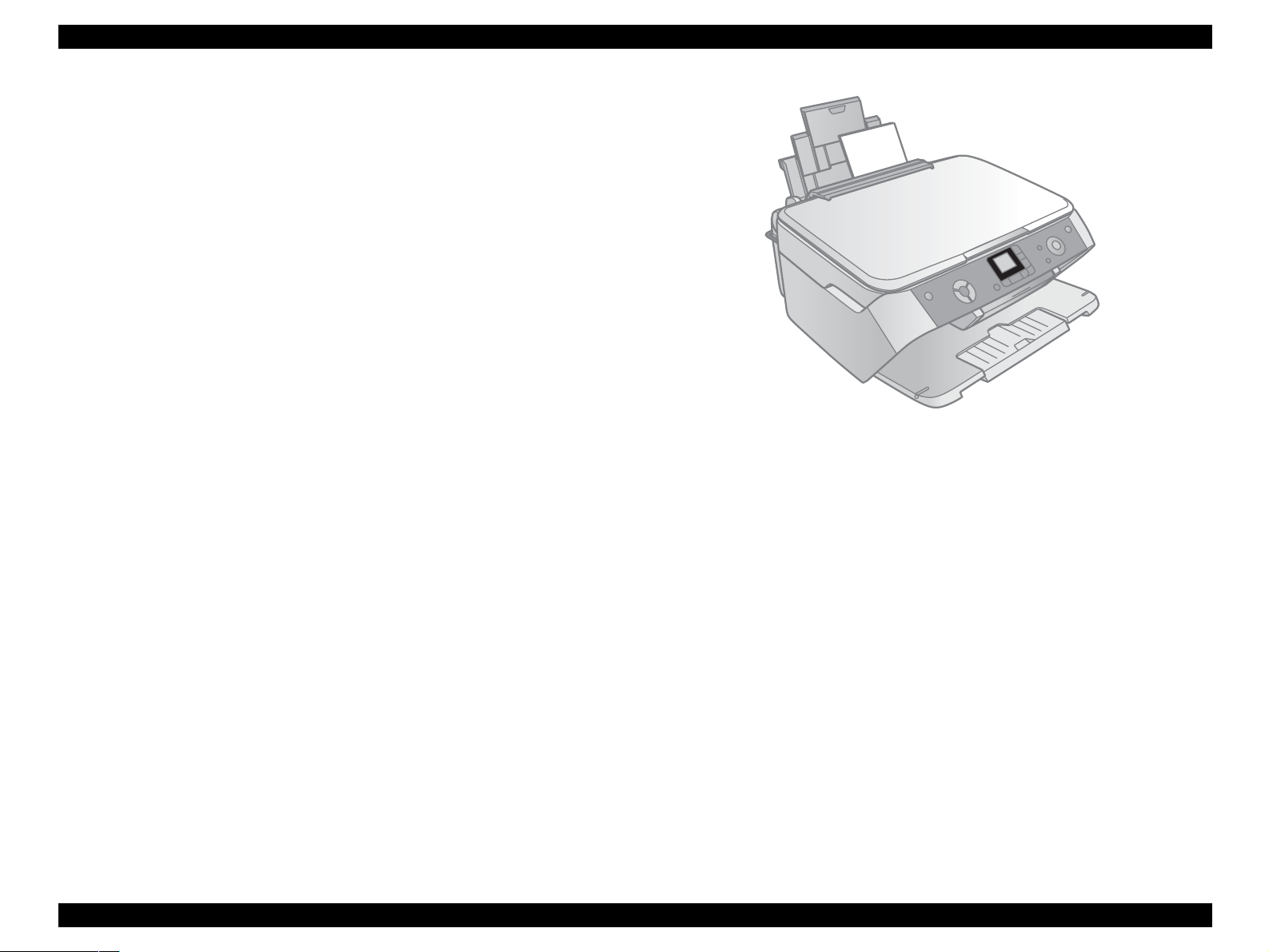
Exterior design
Use of a CIS scanner engine has enabled a more compact design. This unit has
operation panel on the front side, which becomes more distinctive but still easier to
use.
Figure 1-1. External View
EPSON Stylus Photo RX520/RX530 / Stylus CX7700/CX7800 Revision D
PRODUCT DESCRIPTION Specifications 12
1.2 Specifications
1.2.1 Printer Specifications
This section covers specifications of the printer.
1.2.1.1 Physical Specification
Weight
7.8 kg (without the ink cartridges)
Dimension (Including rubber feet, excluding loading tray)
432 mm (W) x 413.2 mm (D) x 198.8 mm (H)
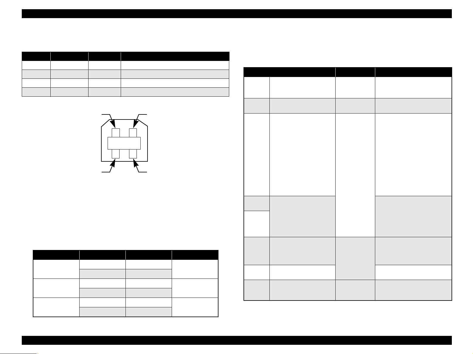
1.2.1.2 Printing Specification
Print method
On-demand ink jet
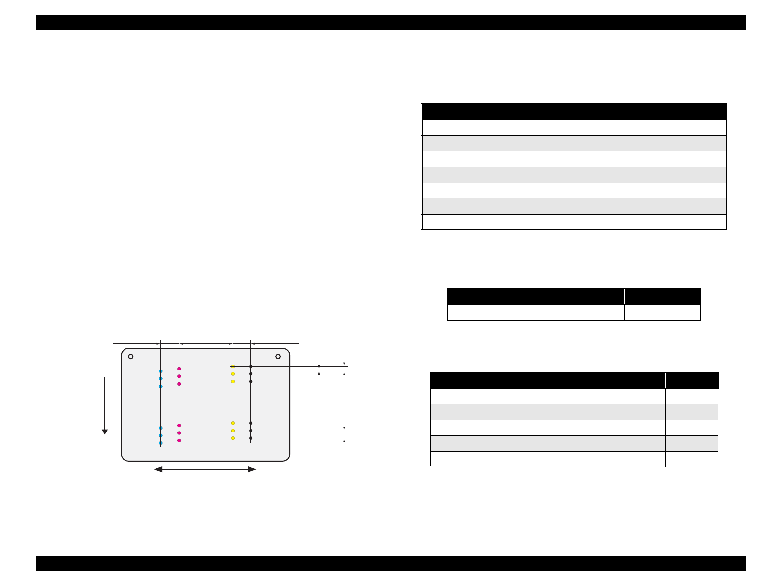
Nozzle configuration
Monochrome: 90 nozzles
Color: 90 nozzles x 3 (Cyan, Magenta, Yellow)
Figure 1-2. Nozzle Configuration
Print direction
Bi-directional minimum distance printing (with logic seeking)
Note "*": These resolution can only be used with the printer driver.
Print speed & printable columns
Note "*": CPS: Characters/Second
This speed is when using normal dot printing mode.
Note "*": Draft Printing
#A3
#A2
#A1
BlackCyan Magenta Yellow
2.822
(40/360inch)
A row B row C row D row
#A90
#A89
#A88
#B3
#B2
#B1
#B89
#B88
#B90
#C3
#C2
#C1
#C89
#C88
#C90
#D3
#D2
#D89
#D88
#D90
#D1
8.467
(120/360inch)
2.822
(40/360inch)
0.2117
(3/360inch)
0.1411
(2/360inch)
0.07055
(1/360inch)
Carriage Moving Direction
Paper Feed Direction
Table 1-2. Print Resolution
Horizontal direction (across columns) Vertical direction (paper feed)
360 dpi 120 dpi
360 dpi 360 dpi
360 dpi 720 dpi
720 dpi 720 dpi
1440 dpi 720 dpi
1440 dpi
*
1440 dpi
*
5760 dpi
*
1440 dpi
*
Table 1-3. Character Mode
Character pitch Printable columns CR speed
10 CPI (Pica) 80 185 CPS*
Table 1-4. Graphics Mode (Standard)
Horizontal resolution Printable area Max. dot count CR speed
360 dpi* 209.8 mm (8.26") 2976 360cps
360 dpi 209.8 mm (8.26") 2976 285cps
720 dpi 209.8 mm (8.26") 5952 220cps
1440 dpi 209.8 mm (8.26") 11904 285cps
5760 dpi 209.8 mm (8.26") 47616 285cps
EPSON Stylus Photo RX520/RX530 / Stylus CX7700/CX7800 Revision D
PRODUCT DESCRIPTION Specifications 13
Note "*": Except Draft Printing
Control code
ESC/P Raster command
EPSON Remote command
ESC/P-R Level-1command
Internal fonts
Character code: Alphanumeric with expanded graphics (PC437)
ASCII, 20H to 7FH only
Fonts: EPSON original fonts
Alphanumeric font: Courier
Input buffer size
64 Kbytes
1.2.1.3 Paper Feed Specifications
Paper feed method
Friction feed, using one ASF (Auto Sheet Feeder)
Paper path
Top feed, front out
Paper feed rates
98.8 mm/sec: high quality mode, 19.05-mm feed
352.8-6.35 mm/sec (13.89-0.25 inch/sec):
high speed mode, continuous feed
PF interval
Programmable in 0.017 mm (1/1440 inch) steps
1.2.1.4 Paper Support
Cut sheets
Table 1-5. Graphics Mode (Border-free Printing)
Horizontal resolution Printable area Max. dot count CR speed
360 dpi* 215.05 mm (8.46") 3048 285 cps
720 dpi 215.05 mm (8.46") 6096 220 cps
1440 dpi 215.05 mm (8.46") 12192 285 cps
5760 dpi 215.05 mm (8.46") 48768 285 cps
Table 1-6. Cut Sheets
Paper size
Dimensions
Thickness Weight Paper type
Width Length
Legal
215.9mm
(8.5")
355.6mm
(14")
0.08-0.11mm
(0.003"-
0.004")
64-90g/m
2
(17-24(lb))
Common paper
Recycled paper
Letter
215.9mm
(8.5")
279.4mm
(11")
A4 210mm 297mm
Executive
184.2mm
(7.25")
266.7mm
(10.5")
B5 182mm 257mm
A5 148mm 210mm
Half Letter
139.7mm
(5.5")
215.9mm
(8.5")
A6 105mm 148mm
User
Defined
50.8-329mm 127-1117.6mm
C A U T I O N
Poor quality paper may reduce print quality and cause paper
jams or other problems. If you encounter problems, switch to a
higher grade of paper.
It is necessary that there is no wrinkle, nap, tear, fold, and so on
in the form.
The curve of form must be 5 mm or below.
Use paper under normal conditions
• Temperature 15 to 25°C (59 to 77°F)
• Humidity 40 to 60% RH
EPSON Stylus Photo RX520/RX530 / Stylus CX7700/CX7800 Revision D
PRODUCT DESCRIPTION Specifications 14
Envelopes
Note *1: Check that the flap is on the long edge and can be folded.
Exclusive papers
Quality: EPSON Exclusive paper
Table 1-7. Envelopes
Paper size
Dimensions
Thickness Weight Paper type
Width Length
No.10 *
1
104.8mm
(4.125")
241.3mm
(9.5")
N/A
75-90g/m
2
(20-24(lb))
Bond paper
Air mail
PPC
DL *
1
110mm 220mm
C6 *
1
114mm 162mm
220 x 132 *
1
132mm 220mm 0.1 82g/m
2
C A U T I O N
Use paper under normal conditions
• Temperature 15 to 25°C (59 to 77°F)
• Humidity 40 to 60% RH
Poor quality paper may reduce print quality and cause paper
jams or other problems. If you encounter problems, switch to a
higher grade of paper.
It is necessary that there is no wrinkle, nap, tear, fold, and so on
in the form.
Don’t use the adhesive envelopes.
Don’t use sleeve insert envelopes and cellophane window
envelopes.
Table 1-8. Exclusive Papers
Item Size
Width
(mm)
Length
(mm)
Thickness
(mm)
Weight
(g/m
2
)
Premium Ink Jet Plain Paper
*1
A4 210 297 0.11 80
Bright White Ink Jet Paper
*1
A4 210 297 0.13 92.5
Photo Quality Self Adhesive
Sheets
*1 *2
A4 210 297 0.19 167
Photo Paper
*1
A4 210 297
0.23 194
4” x 6” 101.6 152.4
Photo Stickers 4/16
*1 *2
A6 105 148 0.19 N/A
Premium Glossy Photo Paper
Letter 215.9 279.4
0.27 255
A4 210 297
8” x 10” 203.2 254
5” X 7” 127 178
4” x 6” 101.6 152.4
3R 89 127
Premium Semigloss Photo Paper
Letter 215.9 279.4
0.27 250
A4 210 297
4” x 6” 101.6 152.4
Matte Paper-Heavyweight
Letter 215.9 279.4
0.23 167A4 210 297
8” x 10” 203.2 254
Iron-On Transfer Paper
*1 *2 *3
Letter 215.9 279.4 TBD TBD
Premium Luster Photo Paper
*1 *2 *3
Letter 215.9 279.4 0.27 250
Double-sided Matte Paper
*1
Letter 215.9 279.4
0.25 178
A4 210 297
Economy Photo Paper
*1
A4 210 297 0.23 188
Iron-On Cool Peel Transfer
Paper
*1 *2 *4
A4 210 297 0.18 124
EPSON Stylus Photo RX520/RX530 / Stylus CX7700/CX7800 Revision D
PRODUCT DESCRIPTION Specifications 15
Note *1: Not supported with stand-alone functions of copy and memory card print.
*2: Only for Stylus Photo RX520/RX530.
*3: Only for Stylus CX7800.
*4: Only for Stylus Photo RX520/RX530/ Stylus CX7700.
Photo Quality Ink Jet paper
*1
A4 210 298
0.12 102
Letter
*2
215.9 279.4
Glossy Photo Paper
*1 *3
4” x 6” 101.6 152.4 0.23 188
Premium Glossy Photo Paper (RC-X) 4” x 6” 101.6 152.4 0.25 238
C A U T I O N
Use paper under normal conditions.
• Temperature 15 to 25°C (59 to 77°F)
• Humidity 40 to 60% RH
Poor quality paper may reduce print quality and cause paper
jams or other problems. If you encounter problems, switch to a
higher grade of paper.
It is necessary that there is no wrinkle, nap, tear, fold, so on in
the form.
The curve of form must be 5mm or below.
Table 1-8. Exclusive Papers
Item Size
Width
(mm)
Length
(mm)
Thickness
(mm)
Weight
(g/m
2
)
EPSON Stylus Photo RX520/RX530 / Stylus CX7700/CX7800 Revision D
PRODUCT DESCRIPTION Specifications 16
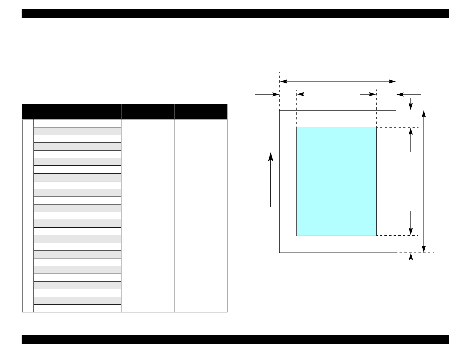
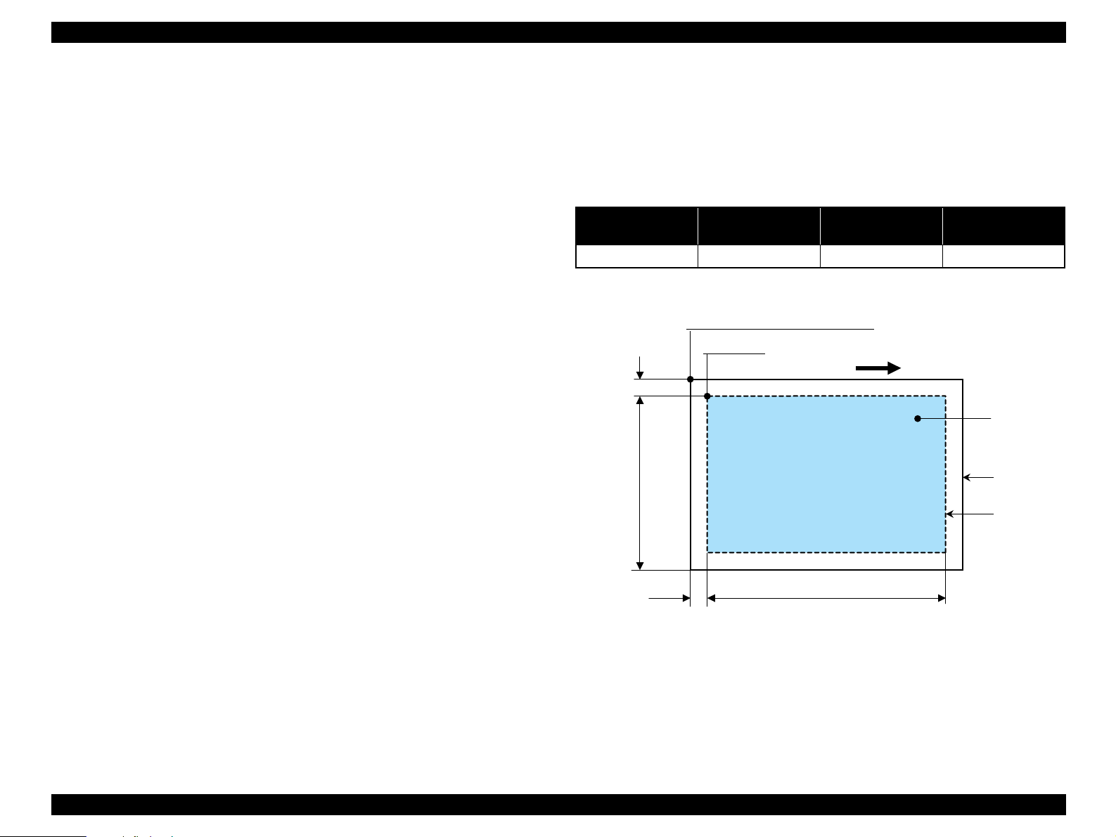
1.2.1.5 Printable Area
Cut sheet (standard printing)
Printable area
The print quality is guaranteed for the print area above the 28.3mm bottom
margin. The print quality is guaranteed for the print area above the 32.1mm top
margin. For paper width (PW) and paper length (PL), refer to
“1.2.1.4 Paper Support” (p.13).
Refer to the following table. As for each margin area, refer to Figure 1-3 (p.16).
Note *1: Not supported with stand-alone functions of copy and memory card print.
*2: Only for Stylus Photo RX520/RX530.
*3: Only for Stylus CX7800.
*4: Only for Stylus Photo RX520/RX530/ Stylus CX7700.
Figure 1-3. Printable Area for Cut Sheet (Standard Printing)
Table 1-9. Applicable Paper/Printable Area
Paper type
Left
margin
Right
margin
Top
margin
Bottom
margin
Cut sheets
Legal
3mm
(0.12")
3mm
(0.12")
3mm
(0.12")
3mm
(0.12")
Letter
A4
Executive
B5
A5
Half Letter
A6
User defined
Exclusive papers
Premium Ink Jet Plain Paper
*1
3mm
(0.12")
3mm
(0.12")
3mm
(0.12")
3mm
(0.12")
Bright White Ink Jet Paper
*1
Photo Quality Self Adhesive Sheets
*1*2
Photo Paper
*1
Photo Sticker 4/16
*1*2
Premium Glossy Photo Paper
Premium Semigloss Photo Paper
Matte Paper-Heavyweight
Iron-On Transfer Paper
*1*2*3
Premium Luster Photo Paper
*1*2*3
Double-sided Matte Paper
*1
Economy Photo Paper
*1
Iron-On Cool Peel Transfer Paper
*1*2*4
Photo Quality Ink Jet Paper
*1
Glossy Photo Paper
*1*3
Premium Glossy Photo Paper
Printable area
LM
RM
PW
TM
BM
PL
Paper Feed Direction
EPSON Stylus Photo RX520/RX530 / Stylus CX7700/CX7800 Revision D
PRODUCT DESCRIPTION Specifications 17
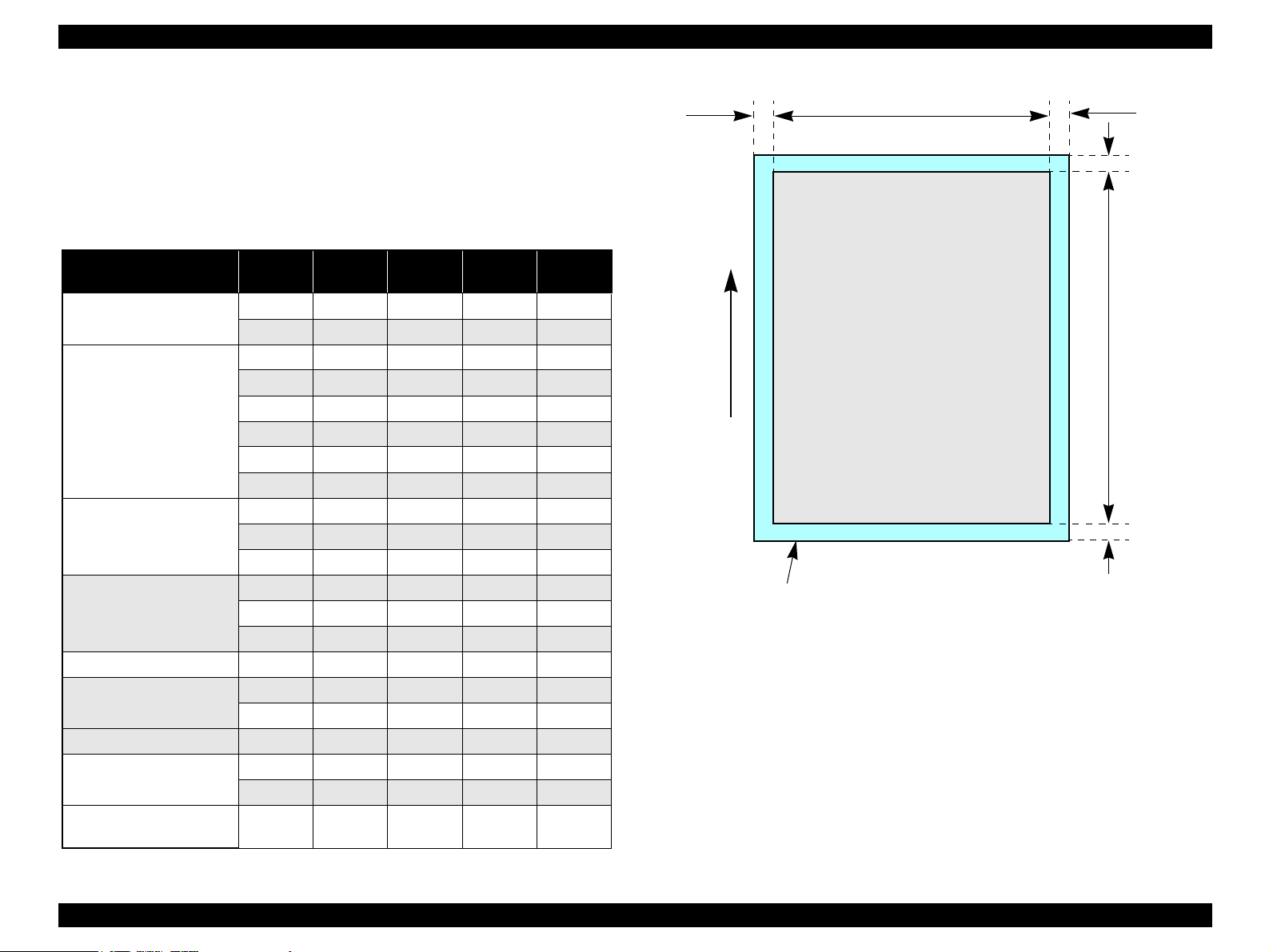
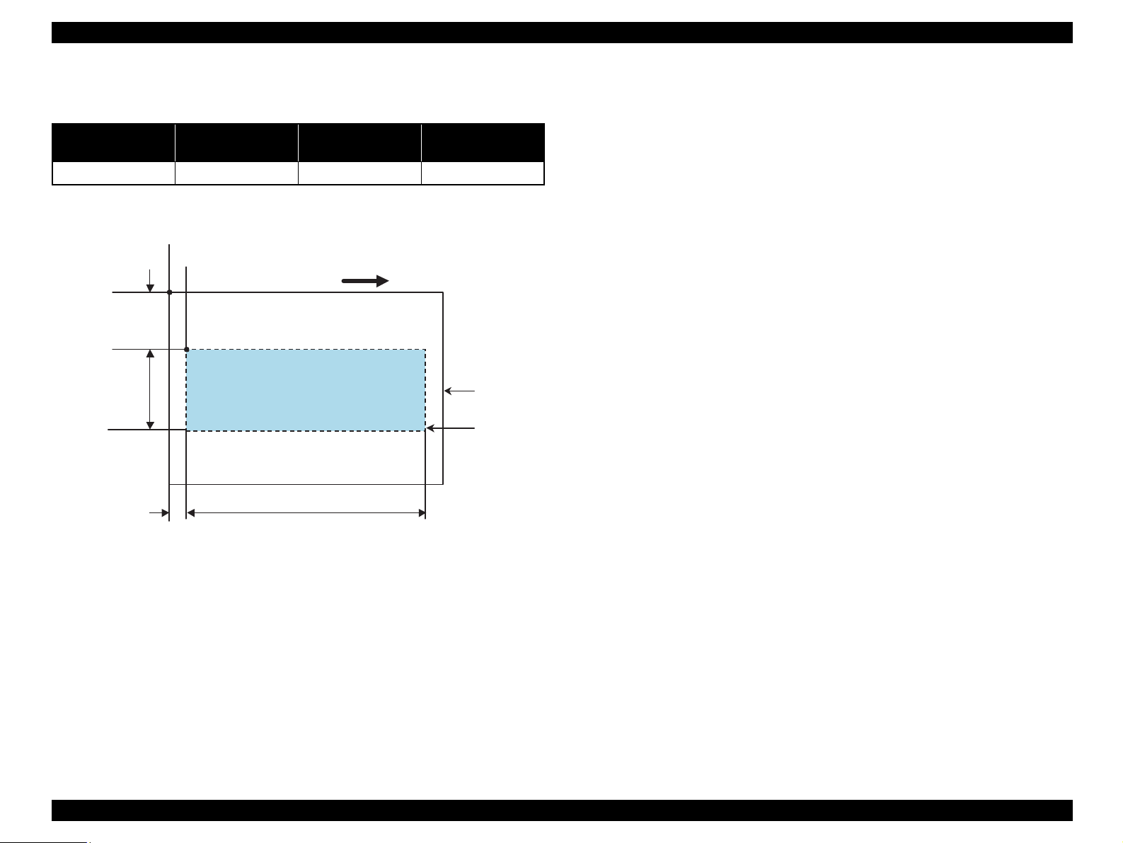
Cut sheet (border-free printing)
Printable area
For paper width (PW) and paper length (PL), refer to
“1.2.1.4 Paper Support” (p.13).
Refer to the following table. As for each overhang area, refer to
Figure 1-4 (p.17).
Figure 1-4. Printable Area for Cut Sheet (Border-free Printing)
Table 1-10. Applicable Paper/Printing Area
Paper type Size
Left
overhang
Right
overhang
Top
overhang
Bottom
overhang
Photo Paper
A4 2.54mm 2.54mm 2.96mm 4.02mm
4” x 6” 2.54mm 2.54mm 1.34mm 2.54mm
Premium Glossy Photo
Paper
Letter 2.54mm 2.54mm 2.96mm 4.02mm
A4 2.54mm 2.54mm 2.96mm 4.02mm
8” x 10” 2.54mm 2.54mm 2.96mm 4.02mm
5” x 7” 2.54mm 2.54mm 2.96mm 4.02mm
4” x 6” 2.54mm 2.54mm 1.34mm 2.54mm
3R 1.83mm 1.83mm 2.54mm 3.53mm
Premium Semigloss Photo
Paper
Letter 2.54mm 2.54mm 2.96mm 4.02mm
A4 2.54mm 2.54mm 2.96mm 4.02mm
4” x 6” 2.54mm 2.54mm 1.34mm 2.54mm
Matte Paper-Heavyweight
Letter 2.54mm 2.54mm 2.96mm 4.02mm
A4 2.54mm 2.54mm 2.96mm 4.02mm
8” x 10” 2.54mm 2.54mm 2.96mm 4.02mm
Premium Luster Photo Paper Letter 2.54mm 2.54mm 2.96mm 4.02mm
Double-sided Matte Paper
Letter 2.54mm 2.54mm 2.96mm 4.02mm
A4 2.54mm 2.54mm 2.96mm 4.02mm
Economy Photo Paper A4 2.54mm 2.54mm 2.96mm 4.02mm
Glossy Photo Paper
Letter 2.54mm 2.54mm 2.96mm 4.02mm
4” x 6” 2.54mm 2.54mm 1.34mm 2.54mm
Premium Glossy Photo
Paper (RC-X)
4” x 6” 2.54mm 2.54mm 1.34mm 2.54mm
Paper size
LO ROPW
TO
BO
Paper Feed Direction
PL
Printable area
EPSON Stylus Photo RX520/RX530 / Stylus CX7700/CX7800 Revision D
PRODUCT DESCRIPTION Specifications 18
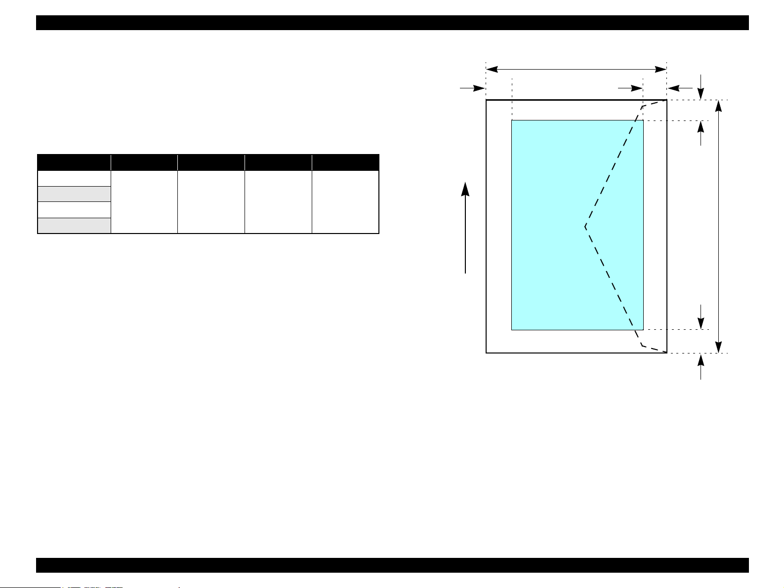
Envelopes
Printable area
For paper width (PW) and paper length (PL), refer to
“1.2.1.4 Paper Support” (p.13).
Refer to the following table. As for each margin area, refer to
Figure 1-5 (p.18).
Figure 1-5. Printable Area for Envelopes
Table 1-11. Applicable Paper/Printing Area
Paper type Left margin Right margin Top margin Bottom margin
No.10
3mm (0.12") 5mm (0.20") 5mm (0.20") 20mm (0.79")
DL
C6
220 x 132
Printable area
LM
TM
RM
BM
Paper Feed Direction
PL
PW
EPSON Stylus Photo RX520/RX530 / Stylus CX7700/CX7800 Revision D
PRODUCT DESCRIPTION Specifications 19
1.2.1.6 Ink Cartridge Specification
Type/color: EPSON-brand special ink cartridges
Print capacity
TBD pages/A4 (ISO/IEC10561 Letter Pattern at 360 dpi)
TBD pages/A4 (360 dpi, 5% coverage)
Shelf life: After packing is opened, it is assumed 6 months, and assumes
2 years including this.
Storage temperature
Dimension : 12.7mm (W) x 73.46mm (D) x 55.25mm (H)
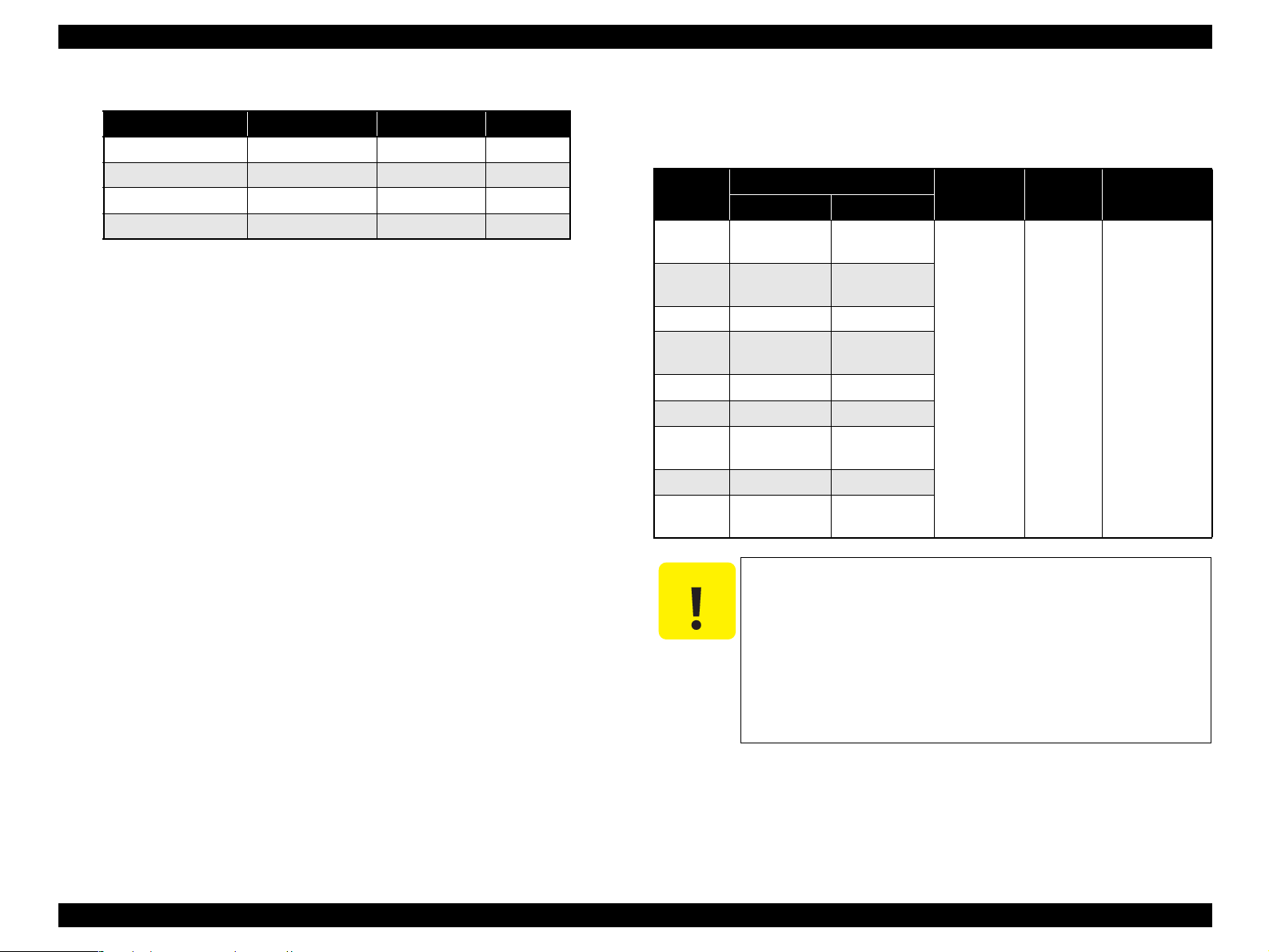
Table 1-12. Ink Cartridge
Color Size
Stylus
CX7700
Stylus
CX7800
Stylus Photo
RX520
Stylus Photo
RX530
Black
S size T0631 T0601 ---- ----
SS size T0621 ---- T0551 T0561
Cyan
S size ---- T0632 ---- ----
SS size T0602 ---- T0552 T0562
Magenta
S size ---- T0633 ---- ----
SS size T0603 ---- T0553 T0563
Yellow
S size ---- T0634 ---- ----
SS size T0604 ---- T0554 T0564
Table 1-13. Storage Temperature
Situation Storage temperature Limit
When stored in individual boxes -30
o
C to 40
o
C
1 month max. at 40
o
C
When installed in main unit -20
o
C to 40
o
C
C A U T I O N
The ink cartridge cannot be refilled.
The ink cartridge that passes the expiration date should not be
used.
The ink in the ink cartridge freezes when leaving it in the
environment of -16°C or under. It takes three hours that the
frozen ink becomes usable when moving it from the
environment of -20°C to the environment of 25°C.
EPSON Stylus Photo RX520/RX530 / Stylus CX7700/CX7800 Revision D
PRODUCT DESCRIPTION Specifications 20
1.2.2 Scanner Specifications
This section covers specifications of the scanner.
1.2.2.1 Basic Specifications
Product type: Flatbed color image scanner
Scanning method: Scanning of fixed document with mobile scan head
Sensor: CIS
Maximum scan area: 8.5" x 11.7" (216mm x 297mm)
Document sizes: A4 or US letter
Max. effective pixels: 10,200 x 14,040 pixels (1200 dpi)
Resolution
Main scan: 1200 dpi
Sub scan: 2400 dpi with Micro Step
Scanning resolution: 50 to 4800 dpi (selectable in 1-dpi steps), 7200 dpi,
9600 dpi
Gradations (pixel depth): Each color pixel has 16-bit input and either 1-bit or 8-
bit output.
Scanning speed: 1200 dpi
Color: Approx. 30msec/line
Monochrome: Approx. 10msec/line
Light source: RGB Three Color LED
Lid-TPU: Scan 35mm film strips with up to six per strip
Scan 35mm film slides with up to four per slide
Built-in 35mm film strip adapter
Support Film: 35mm Color/Mono Negative Film/ 35mm Color
Positive Film
1.2.2.2 Detailed Specifications
Control commands: ESC/I D7
Gamma correction: Two user-defined levels
1.2.2.3 Image Scanning Area
Figure 1-6. Image Scanning Area
Table 1-14. Image Scanning Area
RW
(readable width)
OLM
(out-of-range left margin)
RL
(readable length)
OTM
(out-of-range top margin)
216mm (8.5") 1.5mm ± 1mm 297mm (11.7") 1.5mm ± 1mm
a
Original's top left alignment position
First pixel
Scan direction
Original
(face down)
Scan bed
Scan area
RLOTM
RW
OLM
EPSON Stylus Photo RX520/RX530 / Stylus CX7700/CX7800 Revision D
PRODUCT DESCRIPTION Specifications 21
1.2.2.4 Image Scanning Area of the TPU
Figure 1-7. Image Scanning Area of the TPU
Table 1-15. Image Scanning Area
RW
(readable width)
OLM
(out-of-range left margin)
RL
(readable length)
OTM
(out-of-range top margin)
27.17mm (1.07") 48.4923mm ± 1mm 244mm (9.61") 12.2mm ± 1mm
Original's top left alignment position
First Pixel
Scan direction
OLM
RW
RL
OTM
Original
(face-down)
Scan bed
EPSON Stylus Photo RX520/RX530 / Stylus CX7700/CX7800 Revision D
PRODUCT DESCRIPTION Specifications 22
1.2.3 Common
1.2.3.1 Electric Specification
Primary power input
Note 1: This product complies with the “Energy Star” standards.
2: If the printer is not operated at all for at least three minutes, the standby function
reduces the current to the motor to conserve power.
3: If the scanner is not operated at all for at least 13 minutes, the standby function reduces
the current to the motor to conserve power.
Insulation resistance
10 MΩ minimum (tested between AC line and chassis, test voltage: DC500 V)
Dielectric strength
AC1000 Vrms for one minute or AC1200 Vrms for one second
(100-120 V version)
AC1500 Vrms for one minute (220-240 V version)
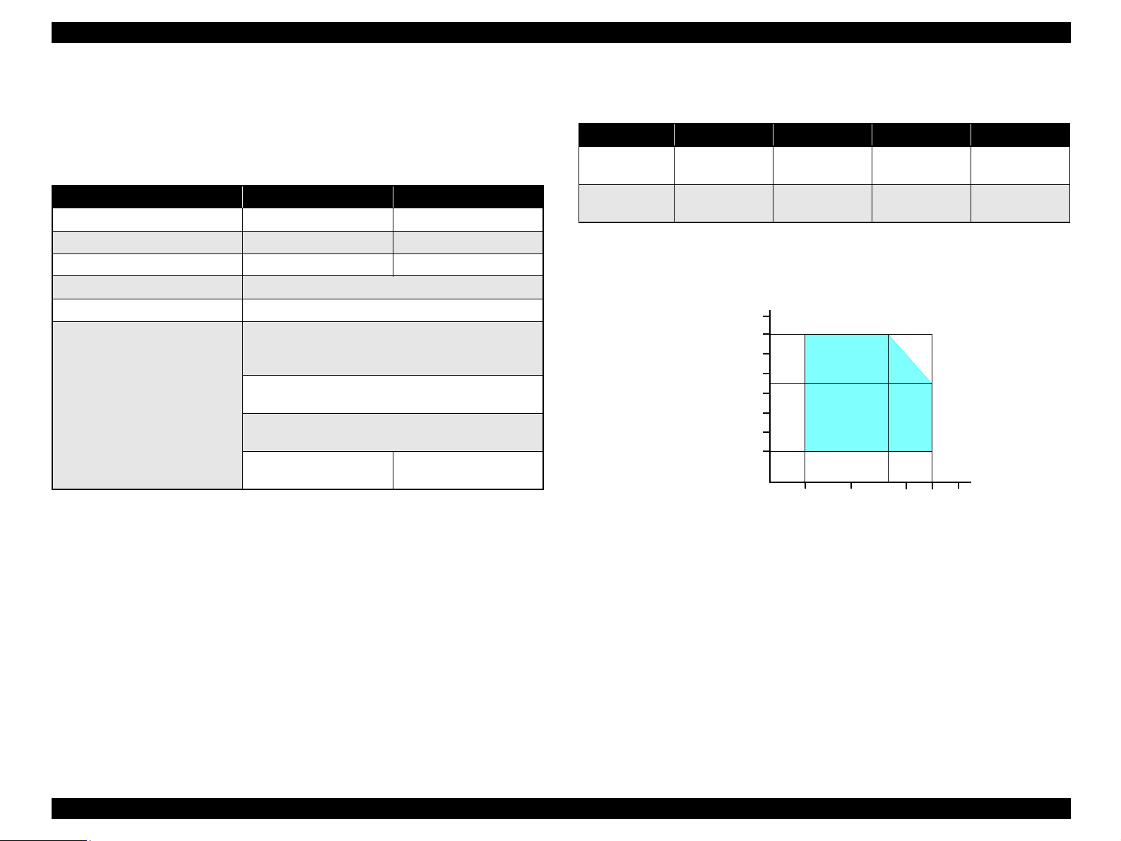
1.2.3.2 Environmental Performance
Note *1: After unpacking (storage)
*2: No condensation
*3: Under the following conditions
Figure 1-8. Temperature/Humidity Range
1.2.3.3 Durability
Total print life: 10,000 pages (black only, A4), or 5 years (whichever
comes first)
Printhead Life: Six billion shots (per nozzle) or 5 years (whichever
comes first)
Scanner head: MCBF: 36,000 cycles
Table 1-16. Primary Power Input
100-120 V model 220-240 V model
Rated power supply voltage (ACV) 100 ~ 120 220 ~ 240
Input voltage range (ACV) 90 ~ 132 198 ~ 264
Rated current (A) 0.4 (Max. 0.7) 0.2 (Max. 0.4)
Rated frequency (Hz) 50 ~ 60
Input frequency range (Hz) 49.5 ~ 60.5
Power consumption (W)
Approx. 13 W
(Standalone copying, ISO10561 Letter Patter, Plain
Paper - Text)
Approx. 6.0 W
(Low-power Mode)
Approx. 1.5 W
(Sleep Mode)
Approx. 0.2 W
(Power Off Mode)
Approx. 0.4 W
(Power Off Mode)
Table 1-17. Environmental Performance
Condition Temperature Humidity *
2
Impact Vibration
Operating 10 ~ 35 °C *
3
20 ~ 80 % *
3
1G,
1 x 10
-3
seconds
0.15 G
Not operating *
1
-20 ~ 40 °C 5 ~ 85 %
2G,
2 x 10
-3
seconds
0.50 G
10 27 30 35 4020
Temperature (°C)
20
30
40
50
90
80
70
60
Humidity (%)
EPSON Stylus Photo RX520/RX530 / Stylus CX7700/CX7800 Revision D
PRODUCT DESCRIPTION Specifications 23
1.2.3.4 Safety Standards: EMC
1.2.3.5 Acoustic Noise
Noise level
45dB (approx.) (according to ISO7779 when for copying)
1.2.3.6 CE Marking
220-240 V version
Low Voltage Directive 73/23/EEC: EN60950
EMC Directive 89/336/EEC: EN55022 Class B
EN61000-3-2
EN61000-3-3
EN55024
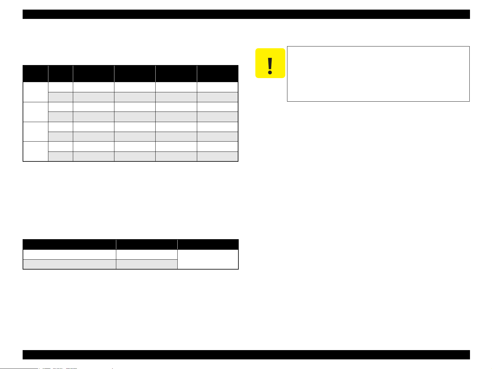
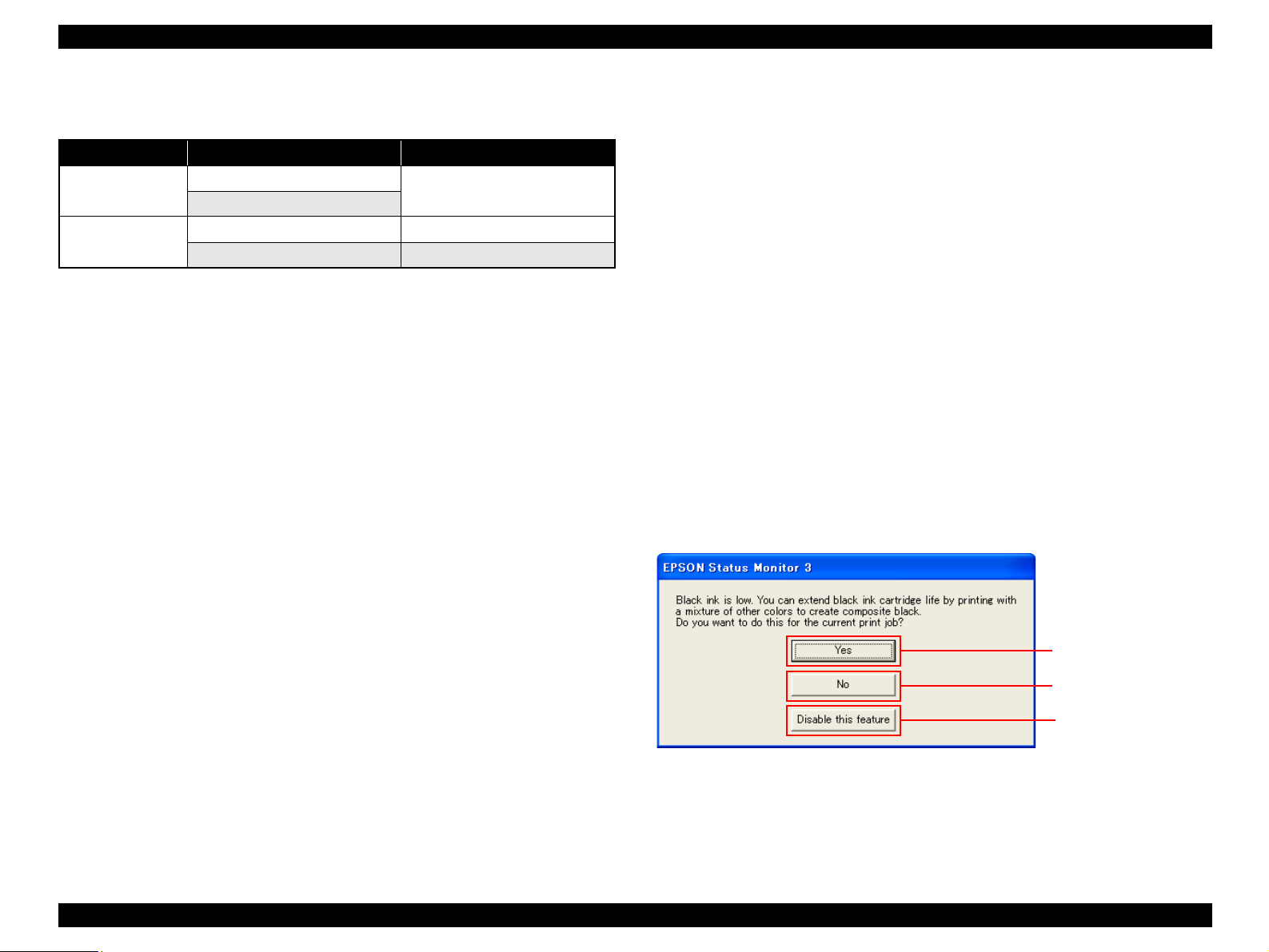
1.2.4 Black Ink Save Mode
(Only for Stylus CX7700/CX7800)
“Black ink save mode” allows you to print images with color ink only when the
remaining amount of black ink is low. This mode can be selected when the remaining
amount of color ink is sufficient since black areas of the images are printed with a
mixture of other colors.
Supported OS: Windows NT4.0, 95, 98, ME, 2000, XP
Printing mode: Plain Paper & Text Mode (360 dpi)
Operating procedure
1. User carries out printing from an application.
2. The printer driver checks both the printing mode and the amount of remaining ink,
and displays the specific window if the conditions described below are all
satisfied.
Selected printing mode supports black ink save mode.
Remaining amount of black ink is less than 5 %, or the status of the black ink
is “ink low”.
Remaining amount of all the color ink is more than 10 %, or the status of all
the color ink is NOT “ink low”.
Table 1-18. Safety Standards: EMC
100-120V version 220-240V version
Safety standards
UL60950
EN 60950
CSA22.2 No.60950
EMI
FCC part15 subpart B class B EN 55022 (CISPR Pub.22) class B
CSA C108.8 class B AS/NZS CISPR22 class B
Starts printing in black ink
save mode.
Starts printing in a normal
manner.
Starts printing in a normal
manner. This window will
not be displayed until the
black ink cartridges is
replaced.
EPSON Stylus Photo RX520/RX530 / Stylus CX7700/CX7800 Revision D
PRODUCT DESCRIPTION Interface 24
1.3 Interface
The EPSON Stylus Photo RX520/RX530 / Stylus CX7700/CX7800 provide the
following interface.
1.3.1 USB Interface
Standards
“Universal Serial Bus Specifications Revision 2.0”
“Universal Serial Bus Device Class Definition for Printing Devices Version
1.1” (printer unit)
“Universal Serial Bus Mass Storage Class Bulk-Only Transport Revision 1.0”
(storage unit)
Transfer rate: 480 Mbps (High Speed Device)
Data format: NRZI
Compatible connector: USB Series B
Recommended cable length: 2 [m] or less
Device ID
Table 1-19. Device ID
Model Name Device ID
Stylus Photo RX520
[00H][65H]
MFG:EPSON;
CMD:ESCPL2,BDC,D4,ESCPR1;
MDL:Stylus[SP]Photo[SP]RX520;
CLS:PRINTER;
DES:EPSON[SP]Stylus[SP]Photo[SP]RX520;
Stylus Photo RX530
[00H][65H]
MFG:EPSON;
CMD:ESCPL2,BDC,D4,ESCPR1;
MDL:Stylus[SP]Photo[SP]RX530;
CLS:PRINTER;
DES:EPSON[SP]Stylus[SP]Photo[SP]RX530;
Stylus CX7700
[00H][5AH]
MFG:EPSON;
CMD:ESCPL2,BDC,D4,ESCPR1;
MDL:Stylus[SP]CX7700;
CLS:PRINTER;
DES:EPSON[SP]Stylus[SP]CX7700;
Stylus CX7800
[00H][5AH]
MFG:EPSON;
CMD:ESCPL2,BDC,D4,ESCPR1;
MDL:Stylus[SP]CX7800;
CLS:PRINTER;
DES:EPSON[SP]Stylus[SP]CX7800;
EPSON Stylus Photo RX520/RX530 / Stylus CX7700/CX7800 Revision D
PRODUCT DESCRIPTION Interface 25
Connector signal layout
Figure 1-9. USB Pin Assignment
Product ID
Stylus Photo RX520/RX530: 0x081A
Stylus CX7700/CX7800: 0x081F
Endpoint attribute
1.3.2 Standard Card Slots
1.3.2.1 Memory Card
Table 1-20. Connector Pin Assignment and Signals
Pin No. Signal name I/O Function description
1 VCC - Cable power. Max. power consumption is 2mA.
2 -Data Bi-D Data
3 +Data Bi-D Data, pull up to +3.3V via 1.5K ohm resistor.
4 Ground - Cable ground
Table 1-21. Endpoint Attribute
I/F No. Endpoint address Endpoint type Linked interface
0x00
0x01 Bulk Out
Scanner
0x02 Bulk In
0x01
0x04 Bulk Out
Printer
0x05 Bulk In
0x02
0x07 Bulk Out
Card
0x08 Bulk In
Pin #1
Pin #3
Pin #2
Pin #4
Table 1-22. Memory Card
Memory card standards Slots Supported memory cards
Compact
Flash
CF+ and CompactFlash
Specification Revision 1.4
compliant
CF Type II slot
• Compact Flash
(memory card only)
• Microdrive
SmartMedia
SmartMedia Standard 2003
compliant
SmartMedia slot
Smart Media
(maximum capacity: 128 MB)
Memory
Stick
MemoryStick Standard version
1.3 compliant
Memory Stick/
Memory Stick
PRO slot
• Memory Stick
(maximum capacity: 128 MB,
including versions with memory
select function)
• MagicGate Memory Stick
(maximum capacity: 128 MB,
copy protection function is not
supported)
• MagicGate Memory Stick Duo
• Memory Stick Duo
(requires Memory Stick Duo
adapter)
Memory
Stick PRO
MemoryStick Standard Memory
Stick PRO Format Specifications
version 1.0 compliant
• Memory Stick PRO
(copy protection function is not
supported)
• Memory Stick PRO Duo
(requires Memory Stick Duo
adapter)
Memory
Stick PRO
Duo
SD
SD Memory Card Specifications
/ PART1. Physical Layer
Specification Version 1.0
compliant
SD/MMC slot
• SD (Secure Digital) memory
card
• miniSD card
(requires SD adapter)
MultiMedia
Card
MultiMediaCard Standard
compliant
MultiMediaCard
xD-Picture
Card
xD-Picture Card
TM
Card
Specification Version 1.20 Type
M compliant
xD-Picture Card
slot
• xD-Picture Card
• xD-Picture Card Type M

EPSON Stylus Photo RX520/RX530 / Stylus CX7700/CX7800 Revision D
PRODUCT DESCRIPTION Interface 26
1.3.2.2 Supported Power Supply Voltage
3.3V/5V (both)
3.3V (only)
NOTE 1: 3.3V power is supplied to media that support both 3.3V and 5V.
2: Maximum current to memory card is 500mA.
3: 5V type memory cards are not supported.
1.3.3 Multi-slot Operations
Overview
Only one type of card can be used to simultaneously access both a connected
computer and the direct printing function.
The slots have assigned priority to determine which slot will be accessed first
when cards are inserted in several slots at once.
To select a card that has been inserted in a non-active slot, the card in the
active slot must first be removed.
• Direct printing:
Only the image files in the active slot are valid and have assigned frame
numbers. The number of images will not change if a card is also inserted in
a non-selected slot.
• Connection to computer (Windows):
Only one drive is displayed at a time as a “removable disk” and only the
card that is in the active slot can be accessed via the removable disk. A card
that has been inserted into a non-selected slot cannot be accessed.
• Connection to computer (Macintosh):
Only the card in the active slot can be mounted on the desktop. A card that
has been inserted into a non-selected slot cannot be mounted on the desktop.
Details
Access priority
The access priority among slots is assigned as:
1: CF (Micro Drive)
2: Smart Media / xD-Picture Card
3: Memory Stick (Memory Stick PRO) / SD (MMC)
Slot selection when power is turned on
If cards are inserted in several slots when the power is turned on, the active
slot is determined by the priority ranks listed above.
Example: If Smart Media and Memory Stick are both inserted at power-on,
the Smart Media slot becomes the active slot.
Slot selection after power is turned on
When a card is removed from the active slot, the slot with the next-highest
priority becomes the active slot (if a card has been inserted into it). There is no
need to re-insert any card before accessing it. If no slots contain any cards, the
highest-priority slot (CF Micro Drive) again becomes the active slot.
Cards can be removed from non-selected slots in any order.
Example: If a memory stick and CF card are inserted while Smart Media is
selected, CF becomes selected (active) once Smart Media is
removed.
C A U T I O N
Note the following caution points when handling the memory card.
Since the SD card and Memory Stick share the same slot, only
one can be inserted at a time.
Since the SmartMedia and xD-Picture Card share the same slot,
only one can be inserted at a time.
When a memory card is being accessed, be sure to keep the
memory card slot’s cover closed and do not touch the memory
card.

EPSON Stylus Photo RX520/RX530 / Stylus CX7700/CX7800 Revision D
PRODUCT DESCRIPTION Stand-alone Copy 27
1.4 Stand-alone Copy
1.4.1 Basic Specifications
1.4.1.1 Supported Paper Sizes, Types and Qualities
Note 1: The quality of draft copy is not affected by “Paper type” selection.
2: Stylus CX7700/CX7800: For photo paper, SN, AF, LUT parameter is same as the Premium Glossy Photo Paper.
Stylus Photo RX520/RX530: For photo paper, SN, AF, LUT parameter is same as the Ultra Glossy Photo Paper (EU)/Ultra Premium Glossy Photo Paper (EAI).
3: 13x18: The panel indicator only. The Printer chalks the 13x18 format up to the 5x7 format.
4: 10x15: The panel indicator only. The Printer chalks the 10x15 format up to the 4x6 format.
Note *1: Connected with Paper type.
*2: Printing is available, however, LUT (color tone) is not guaranteed for Stylus CX7700/CX7800.
*3: Only for Stylus Photo RX520/RX530.
Table 1-23. Supported Paper Size, Types, and Qualities
Paper type
Quality
*1
Stylus CX7700/CX7800 Stylus Photo RX520/RX530
Paper name Panel indication Paper size Panel indication Paper size Panel indication
Plain Paper
Recycled Paper
Bright White Paper
Plain Paper Plain Paper Letter Letter A4 A4
Premium Glossy Photo Paper Photo Paper Photo Paper
Letter
5” x 7”
4” x 6”
Letter
5” x 7”
4” x 6”
A4
13 x 18
10 x 15
A4
13 x 18/5” x 7”
10 x 15/4” x 6”
Premium Semigloss Photo Paper Photo Paper Photo Paper Letter Letter
A4
10 x 15
A4
10 x 15/4” x 6”
Premium Luster Photo Paper
*3
Photo Paper Photo Paper Letter Letter
A4
13 x 18
10 x 15
A4
13 x 18/5” x 7”
10 x 15/4” x 6
Ultra Premium Glossy Photo Paper
*2
Photo Paper Photo Paper
Letter
5” x 7”
4” x 6”
Letter
5” x 7”
4” x 6”
A4
13 x 18
10 x 15
A4
13 x 18
10 x 15
Matte Paper-Heavyweight Matte Paper Matte Paper Letter Letter A4 A4
EPSON Stylus Photo RX520/RX530 / Stylus CX7700/CX7800 Revision D
PRODUCT DESCRIPTION Stand-alone Copy 28
1.4.1.2 Zoom Function
The zoom function provides enlarged or reduced copies of originals. Either of the
following can be selected from the operation panel.
Actual (The state which “Fit to page” is not selected. It is the power-on default.)
The zoom factor is set to 100%.
Fit to page
This function detects the image size of the original and automatically sets the
zoom factor of the copy according to the copy paper’s printable area.
1.4.1.3 Number of Copies Setting
This function sets the number of copies. The setting range is 1 to 99.
1.4.1.4 Maximum Copy Size
216 x 297mm
1.4.1.5 Copy Layout
The following copy layout is provided according to “Paper type”, “Paper size” and
zoom selections.
Standard copy
Provided for ordinary use with 3mm copy margin from every side.
BorderFree copy
Border-free printing of copies occurs when the print area is set as larger than the
copy paper’s size. In such cases, the outer edges of the original image may be
omitted in the printed copy.
Small Margins copy
This function sets a 1.5mm margin on all four sides when printing in order to make
maximum use of the original image and copy paper.
NOTE: Only “Standard Copy” can be used in draft copy mode.
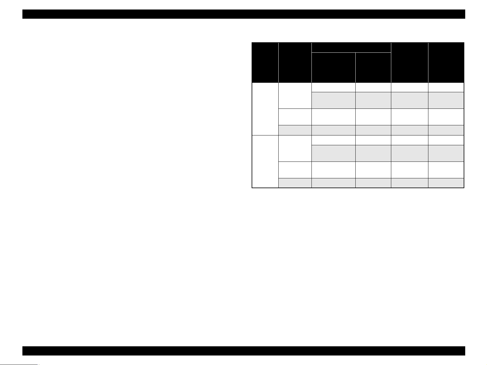
Note : 10x15:
The panel indicator only.The Printer chalks the 10x15 format up to the 4x6 format.
Note *1: Actual is the state that “Fit to page” is not selected.
*2: “Fit to page” automatically sets the enlarge/reduce scale so that the entire image fits
into the printable area or the border free area when border free layout is selected.
When the original image is smaller than general card size (approx. 54mm x 86mm),
the print margins will be different from the one that is defined by each layout.
The image placement uses the upper left corner as the origin and any margins that
occur during the fitting process occur along the bottom and/or right edge.
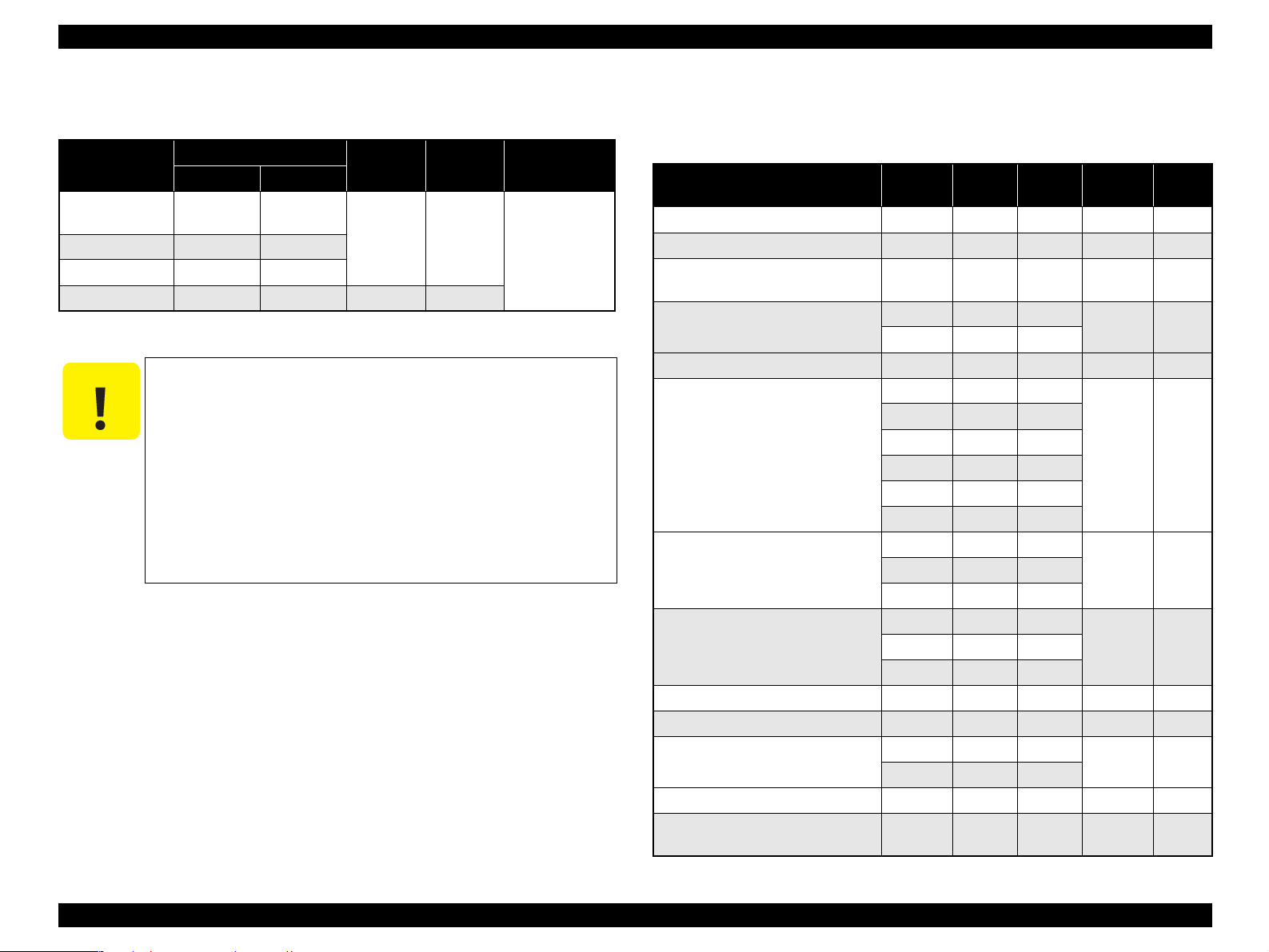
Table 1-24. Copy Layout
Zoom Paper type
Paper size
B&W / Color Layout
Stylus CX 7800
Stylus Photo
RX520/
RX530/
CX7700
Actual *
1
Plain Paper
Letter A4 B&W, Color Standard
4” x 6”, 5” x 7”
10 x 15,
13 x 18
B&W, Color Standard
Photo Paper
Letter, 4” x 6”,
5” x 7”
A4, 10 x 15,
13 x 18
B&W, Color Small margin
Matte Paper Letter A4 B&W, Color Small margin
Fit to
page *
2
Plain Paper
Letter A4 B&W, Color Standard
4” x 6”, 5” x 7”
10 x 15,
13 x 18
B&W, Color Standard
Photo Paper
Letter, 4” x 6”,
5” x 7”
A4, 10 x 15,
13 x 18
B&W, Color Border free
Matte Paper Letter A4 B&W, Color Border free

EPSON Stylus Photo RX520/RX530 / Stylus CX7700/CX7800 Revision D
PRODUCT DESCRIPTION Stand-alone Copy 29
1.4.1.6 Multiple Copies from an Original
Second and subsequent copies can be printed from an original without scanning.
When printing two or more copies, under the following settings the scan data can be
stored in the unit’s memory so that the second and subsequent copies can be printed
without scanning.
“Draft” mode (monochrome/color)
“Text” mode (monochrome)
1.4.2 Copy Speed (TBD)
1.4.2.1 Black Copy Speed
Plain Paper – Draft TBD cpm (Copy per minute), Plain Paper – TBD cpm
Black e-Memo text A4 size pattern, zoom 100%
The above speed is for the second and subsequent copies (the time between
ejection of the first page to ejection of the second page).
1.4.2.2 Color Copy Speed
Plain Paper – Draft TBD cpm (Copy per minute)
Color e-Memo text A4 size pattern, zoom 100%
The above speed is for the second and subsequent copies (the time between
ejection of the first page to ejection of the second page)
1.4.3 Configuration for Copying
Note *1: “Default” is the state in which “Fit to page” is not selected. When “Fit to page” is
selected, scan resolution will be optimized according to enlarge/reduce scale.
*2: Pure black will be used in both B&W and color mode.
*3: With “Draft”, both real black and composite black will be used for black printing.
Table 1-25. Configuration for Copying (For Stylus CX7700/CX7800)
Copy mode setting Scan and print configuration
Panel
indication*
4
B&W /
Color
Enlarge /
Reduce*
1
(%)
Print
resolution
(H x V dpi)
Dot size MW
High
speed
LUT
Draft (Plain
paper only)
B&W
*
3
100 (Default) 360 x 120 Eco Off On CB1:Plain
Color
*
3
100 (Default) 360 x 120 Eco Off On CC1:Plain
Plain Paper
B&W
*
2
100 (Default) 360 x 360 VSD1 Off On CB2:Plain
Color
*
2
100 (Default) 360 x 720 VSD1 On On CC2:Plain
B&W
*
2
100 (Default) 720 x 720 VSD3 On On CB5:Plain
Color
*
2
100 (Default) 720 x 720 VSD3 On On CC5:Plain
Photo Paper
B&W 100 (Default) 720 x 720 VSD2 On On CC3:SR-C
Color 100 (Default) 720 x 720 VSD2 On On CC3:SR-C
Matte Paper
B&W
*
2
100 (Default) 720 x 720 VSD2 On On CB4:Matte
Color
*
2
100 (Default) 720 x 720 VSD2 On On CB4:Matte
Table 1-26. Configuration for Copying (For Stylus Photo RX520/RX530)
Copy mode setting Scan and print configuration
Panel
Indication*
4
B&W /
Color
Enlarge /
Reduce*
1
(%)
Print
resolution
(H x V dpi)
Dot size MW
High
speed
LUT
Draft (Plain
paper only)
B&W
*
3
100 (Default) 360 x 120 Eco Off On CB1:Plain
Color
*
3
100 (Default) 360 x 120 Eco Off On CC1:Plain
Plain Paper
B&W
*
2
100 (Default) 360 x 360 VSD1 On On CB2:Plain
Color
*
2
100 (Default) 360 x 720 VSD1 On On CC2:Plain
B&W
*
2
100 (Default) 720 x 720 VSD3 On On CB5:Plain
Color
*
2
100 (Default) 720 x 720 VSD3 On On CC5:Plain
Photo Paper
B&W 100 (Default) 720 x 720 VSD2 On On CC3:Ultra
Color 100 (Default) 720 x 720 VSD2 On On CC3:Ultra
Matte Paper
B&W
*
2
100 (Default) 720 x 720 VSD2 On On CB4:Matte
Color
*
2
100 (Default) 720 x 720 VSD2 On On CB4:Matte
EPSON Stylus Photo RX520/RX530 / Stylus CX7700/CX7800 Revision D
PRODUCT DESCRIPTION Stand-alone Copy 30
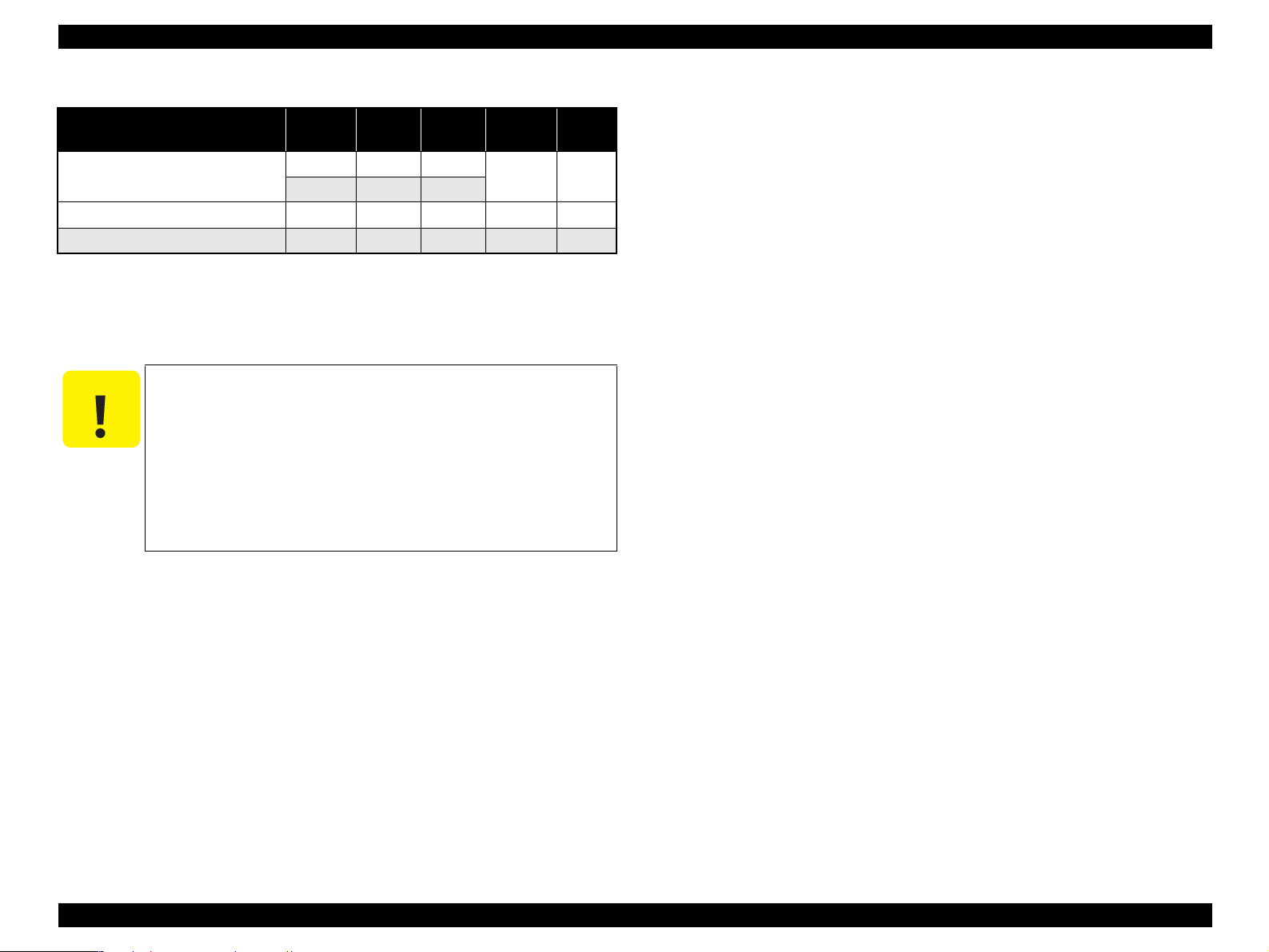
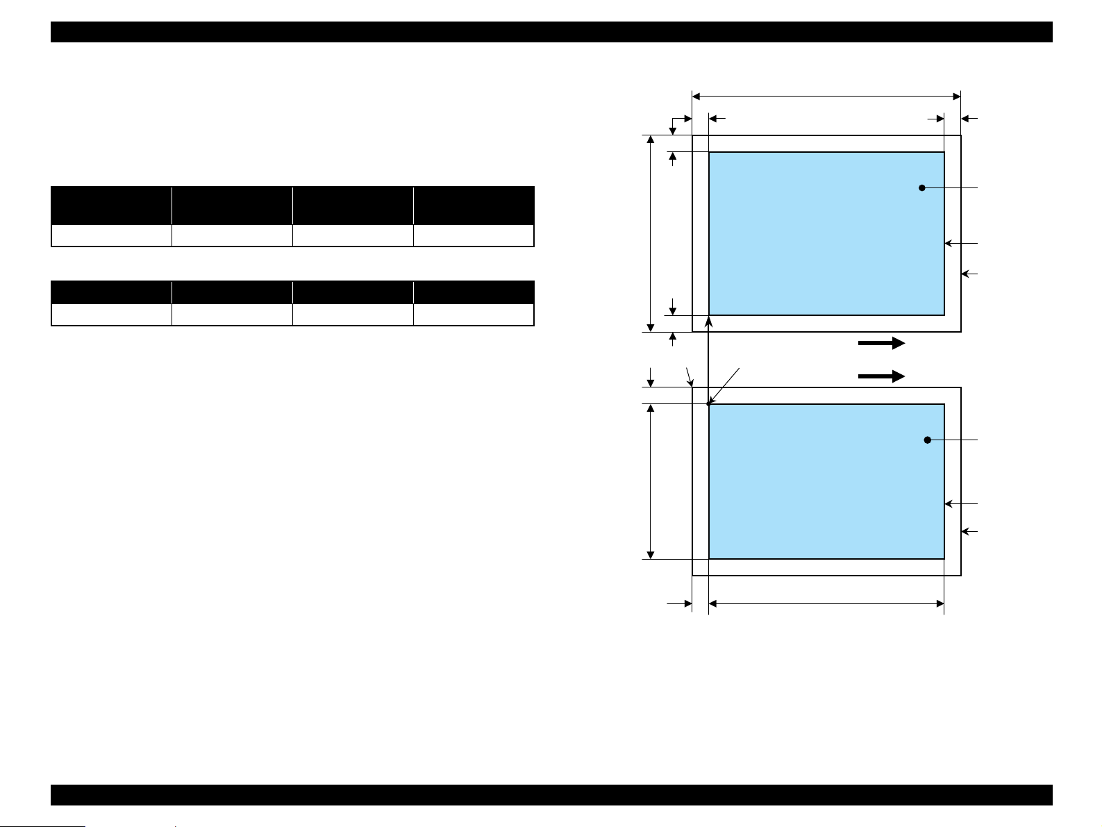
1.4.4 Relation between original and copy
1.4.4.1 Standard Copy
The following table shows the relative positioning of the original and copy.
Note : Refer to “1.2.1.4 Paper Support” (p.13) for paper width (PW) and paper length (PL).
Figure 1-10. Standard Copy
Table 1-27. Original (scanner)
RW
(readable width)
OLM
(out-of-range left margin)
RL
(readable length)
OTM
(out-of-range top margin)
216mm (8.5") 3mm 297mm (11.7") 3mm
Table 1-28. Copy (printer)
RM LM TM BM
3mm (0.12") 3mm (0.12") 3mm (0.12") 3mm (0.12")
a
a
Copy
Print area
Copy paper
Print direction
Scan direction
Right side of copy
Right side of original
Original
(face down)
Scan area
Scan bed
BMTM
PL
RM
LM
TopPW
*2*1
OLM
TopRW
OTM RL
Note *1: This indicates the top left corner of the original. Normally, this corner is aligned
with the scan bed’s top right corner as the reference point.
*2: This indicates the scan start position at the top left of the original, which
corresponds to the print start position at the top left of the copy. The bottom right
corner position of the copy is within the print area but varies according to the
enlarge/reduce setting.
Loading...