


 Loading...
SERVICE MANUAL
Color Inkjet Printer
EPSON STYLUS PHOTO 720 / STYLUS PHOTO EX3
EPSON Stylus Photo 720
EPSON Stylus Photo EX3
SEIJ00001
PRECAUTIONS
Precautionary notations throughout the text are categorized relative to 1)Personal injury and 2) damage to equipment.
DANGER Signals a precaution which, if ignored, could result in serious or fatal personal injury. Great caution should be exercised in performing procedures preceded by DANGER Headings.
WARNING Signals a precaution which, if ignored, could result in damage to equipment.
The precautionary measures itemized below should always be observed when performing repair/maintenance procedures.
DANGER
1.ALWAYS DISCONNECT THE PRODUCT FROM THE POWER SOURCE AND PERIPHERAL DEVICES PERFORMING ANY MAINTENANCE OR REPAIR PROCEDURES.
2.NO WORK SHOULD BE PERFORMED ON THE UNIT BY PERSONS UNFAMILIAR WITH BASIC SAFETY MEASURES AS DICTATED FOR ALL ELECTRONICS TECHNICIANS IN THEIR LINE OF WORK.
3.WHEN PERFORMING TESTING AS DICTATED WITHIN THIS MANUAL, DO NOT CONNECT THE UNIT TO A POWER SOURCE UNTIL INSTRUCTED TO DO SO. WHEN THE POWER SUPPLY CABLE MUST BE CONNECTED, USE EXTREME CAUTION IN WORKING ON POWER SUPPLY AND OTHER ELECTRONIC COMPONENTS.
WARNING
1.REPAIRS ON EPSON PRODUCT SHOULD BE PERFORMED ONLY BY AN EPSON CERTIFIED REPAIR TECHNICIAN.
2.MAKE CERTAIN THAT THE SOURCE VOLTAGES IS THE SAME AS THE RATED VOLTAGE, LISTED ON THE SERIAL NUMBER/ RATING PLATE. IF THE EPSON PRODUCT HAS A PRIMARY AC RATING DIFFERENT FROM AVAILABLE POWER SOURCE, DO NOT CONNECT IT TO THE POWER SOURCE.
3.ALWAYS VERIFY THAT THE EPSON PRODUCT HAS BEEN DISCONNECTED FROM THE POWER SOURCE BEFORE REMOVING OR REPLACING PRINTED CIRCUIT BOARDS AND/OR INDIVIDUAL CHIPS.
4.IN ORDER TO PROTECT SENSITIVE MICROPROCESSORS AND CIRCUITRY, USE STATIC DISCHARGE EQUIPMENT, SUCH AS ANTI-STATIC WRIST STRAPS, WHEN ACCESSING INTERNAL COMPONENTS.
5.REPLACE MALFUNCTIONING COMPONENTS ONLY WITH THOSE COMPONENTS BY THE MANUFACTURE; INTRODUCTION OF SECOND-SOURCE ICs OR OTHER NONAPPROVED COMPONENTS MAY DAMAGE THE PRODUCT AND VOID ANY APPLICABLE EPSON WARRANTY.

About This Manual
This manual describes basic functions, theory of electrical and mechanical operations, maintenance and repair procedures of EPSON Stylus Photo 720 / Stylus Photo EX3. The instructions and procedures included herein are intended for the experienced repair technicians, and attention should be given to the precautions on the preceding page.
Contents
This manual consists of six chapters and Appendix.
CHAPTER 1.PRODUCT DESCRIPTIONS
Provides a general overview and specifications of the product.
CHAPTER 2.OPERATING PRINCIPLES
Describes the theory of electrical and mechanical operations of the product.
CHAPTER 3.TROUBLESHOOTING
Provides the step-by-step procedures for the troubleshooting.
CHAPTER 4.DISASSEMBLY AND ASSEMBLY
Describes the step-by-step procedures for disassembling and assembling the product.
CHAPTER 5.ADJUSTMENTS
Provides Epson-approved methods for adjustment.
CHAPTER 6.MAINTENANCE
Provides preventive maintenance procedures and the lists of Epson-approved lubricants and adhesives required for servicing the product.
APPENDIXProvides the following additional information for reference:
•Connector pin assignments
•Electric circuit boards components layout
•Exploded diagram
•Electrical circuit boards schematics
Symbols Used in This Manual
Various symbols are used throughout this manual either to provide additional information on a specific topic or to warn of possible danger present during a procedure or an action. Be aware of all symbols when they are used, and always read WARNING, CAUTION or NOTE messages.
W A R Indicates an operating or maintenance procedure, practice or condition that, if not strictly observed, could result in injury or loss of life.
Indicates an operating or maintenance procedure, practice,
C A U T IO N
or condition that, if not strictly observed, could result in damage to, or destruction of, equipment.
May indicate an operating or maintenance procedure,
C H E
P O I practice or condition that is necessary to accomplish a task  efficiently. It may also provide additional information that is related to a specific subject, or comment on the results achieved through a previous action.
Revision Status
Revision |
Issued Date |
Description |
|
|
|
Rev. A |
April 6, 2000 |
First Release |
|
|
|
|
|
|
|
|
|
|
|
|
|
|
|
|
|
|
|
|
|

EPSON Stylus Photo 720 / EPSON Stylus Photo EX3 |
Revision A |
Contents
Product Description |
|
Overview ....................................................................................................... |
9 |
Features ................................................................................................... |
9 |
Basic Specification .................................................................................... |
10 |
Printing Specification .............................................................................. |
10 |
Paper Feed specification ........................................................................ |
11 |
Input Data Buffer .................................................................................... |
11 |
Electric Specification .............................................................................. |
11 |
Environmental Conditions ...................................................................... |
12 |
Reliability ................................................................................................ |
12 |
Safety Approvals .................................................................................... |
12 |
Acoustic Noise ........................................................................................ |
12 |
CE Marking ............................................................................................. |
12 |
Interface Specification .............................................................................. |
13 |
IEEE-1284 Parallel I/F (Forward Channel) ............................................. |
13 |
IEEE-1284 Parallel I/F (Reverse Channel) ............................................. |
13 |
USB (Universal Serious Bus) ................................................................. |
16 |
Miscellanea ............................................................................................ |
16 |
Preventing Hosts from Data Transfer Time-out .................................. |
16 |
Interface Selection .............................................................................. |
16 |
IEEE 1284.4 protocol ......................................................................... |
17 |
Control Specification ................................................................................ |
18 |
Control Panel .......................................................................................... |
18 |
Control Switches .................................................................................... |
18 |
Code Page Selection/ Parallel I/F IEEE1284.4 Setting ...................... |
19 |
Special Setting Mode ......................................................................... |
20 |
LED Indications ...................................................................................... |
20 |
Initialization ............................................................................................. |
21 |
Errors ...................................................................................................... |
21 |
Paper ........................................................................................................... |
22 |
Paper handling ....................................................................................... |
22 |
Paper Specification ................................................................................ |
22 |
Printable Area ........................................................................................ |
24 |
Ink Cartridge ........................................................................................... |
26 |
Physical Specification .............................................................................. |
27 |
Consumables and Options ....................................................................... |
28 |
Operating Principles |
|
Overview .................................................................................................... |
30 |
Printer Mechanism ................................................................................. |
30 |
Printhead ................................................................................................ |
32 |
Printing Process ................................................................................. |
33 |
Printing Method .................................................................................. |
34 |
Carriage Mechanism .............................................................................. |
35 |
Platen Gap (PG) Adjustment Mechanism .......................................... |
35 |
Paper Feeding Mechanism .................................................................... |
36 |
Paper Loading Mechanism (ASF Unit) ................................................... |
37 |
Ink System Mechanism .......................................................................... |
39 |
Pump Unit and CR Lock Mechanism ................................................. |
39 |
Capping Mechanism .............................................................................. |
40 |
Ink Sequence ......................................................................................... |
41 |
Electrical Circuit Operating Principles .................................................... |
42 |
C301PSB/PSE Board ............................................................................. |
42 |
C301MAIN Board ................................................................................... |
44 |
Main elements .................................................................................... |
45 |
Printhead Driver Circuit ...................................................................... |
45 |
PF Motor (PF/ PUMP/ ASF Motor) Driver Circuit ............................... |
47 |
CR Motor Driver Circuit ...................................................................... |
48 |
Reset Circuit ....................................................................................... |
48 |
EEPROM Control Circuit .................................................................... |
49 |
Sensor Circuit ..................................................................................... |
50 |
6

EPSON Stylus Photo 720 / EPSON Stylus Photo EX3 |
Revision A |
Troubleshooting |
|
Overview ..................................................................................................... |
52 |
Unit Level Troubleshooting ...................................................................... |
54 |
Printer does not operate at power on ..................................................... |
54 |
Error is detected ..................................................................................... |
55 |
Failure occurs during printing ................................................................. |
55 |
Printer does not feed paper correctly ..................................................... |
56 |
Control panel operation is abnormal ...................................................... |
56 |
Unit Repair (Power Supply Board) ........................................................... |
57 |
Unit Repair (Control Board) ...................................................................... |
58 |
Unit Repair (Printer Mechanism) .............................................................. |
60 |
Disassembly and Assembly |
|
Overview ..................................................................................................... |
65 |
Precautions ............................................................................................ |
65 |
Tools ....................................................................................................... |
65 |
Work Completion Check ......................................................................... |
66 |
Disassembly ............................................................................................... |
67 |
Housing Removal ................................................................................... |
68 |
Circuit Board Assembly Removal ........................................................... |
69 |
Control Panel Removal .......................................................................... |
71 |
Ink Absorber Tray Assembly (Waste Ink Pad) Removal ........................ |
72 |
Printer Mechanism Disassembly ............................................................ |
73 |
Printhead Removal ............................................................................. |
73 |
Pump Assembly / Cap Assembly Removal ........................................ |
75 |
CR Motor Assembly Removal ............................................................ |
77 |
PF Motor Assembly Removal ............................................................. |
78 |
ASF Assembly Removal ..................................................................... |
80 |
ASF LD Roller Assembly Removal ..................................................... |
82 |
LD Roller Assembly Disassembly ....................................................... |
87 |
CR Assembly Removal ...................................................................... |
88 |
PE Sensor Assembly Removal .......................................................... |
90 |
PF Roller Assembly Removal ............................................................. |
91 |
CR HP Sensor Removal ..................................................................... |
93 |
Adjustment |
|
Overview .................................................................................................... |
95 |
Required Adjustment .............................................................................. |
95 |
Adjustment ................................................................................................. |
96 |
PG Adjustment ....................................................................................... |
96 |
Adjustment by Adjustment Program ....................................................... |
98 |
Adjustment Program .............................................................................. |
98 |
Adjustment Program Installation Procedure ........................................... |
98 |
Adjustment Program Initial Setting Screen ............................................ |
99 |
Market Destination Check .................................................................... |
100 |
Head Voltage ID Input .......................................................................... |
101 |
Head Angular Adjustment .................................................................... |
103 |
Bi-Directional Adjustment ..................................................................... |
106 |
USB ID Check/Input ............................................................................. |
109 |
Head Cleaning ..................................................................................... |
110 |
Initial Ink Charge .................................................................................. |
111 |
Protection Counter Check/Clear .......................................................... |
111 |
Print A4 Pattern .................................................................................... |
113 |
Maintenance |
|
Overview .................................................................................................. |
115 |
Cleaning ............................................................................................... |
115 |
Service Maintenance ............................................................................ |
116 |
Lubrication ............................................................................................ |
117 |
Appendix |
|
Connector Summary ............................................................................... |
122 |
Major Component Unit ......................................................................... |
122 |
EEPROM Address Map ....................................................................... |
125 |
Component Layout .................................................................................. |
129 |
Exploded Diagram ................................................................................... |
131 |
Parts List .................................................................................................. |
139 |
Electric Circuit ......................................................................................... |
149 |
7

C H A P T E R
1
PRODUCT DESCRIPTION

EPSON Stylus Photo 720 / EPSON Stylus Photo EX3
1.1 Overview
Stylus Photo 720 and Stylus Photo EX3 is developed from Stylus Photo 700 and Stylus Photo EX and allows a high resolution photographic high quality print enabled by variable dot.
1.1.1 |
Features |
|
Major features of this printer are as follows; |
||
o |
High color print quality |
|
|
n |
1440x720 (HxV) dpi printing |
|
n |
Photo-MACH technology (6 color printing. CMYKLmLc) |
|
n |
Traditional and New Microweave |
o |
Built-in ASF (Auto Sheet Feeder) |
|
|
n |
Holds 100 cut-sheets (64 g/m2) |
|
n |
Holds 10 envelopes |
|
n |
Holds 30 transparency films |
o |
Built-in 2 I/F |
|
|
n |
Bi-directional parallel I/F (IEEE-1284 level 1 device) |
|
n |
USB (Universal Serial Bus) |
o |
Windows / Macintosh exclusive |
|
Revision A
Stylus Photo 720
Stylus Photo EX3
Figure 1-1. External View
Product Description |
Overview |
9 |
EPSON Stylus Photo 720 / EPSON Stylus Photo EX3
1.2 Basic Specification
1.2.1 Printing Specification
PRINTING METHOD
o |
On demand ink jet |
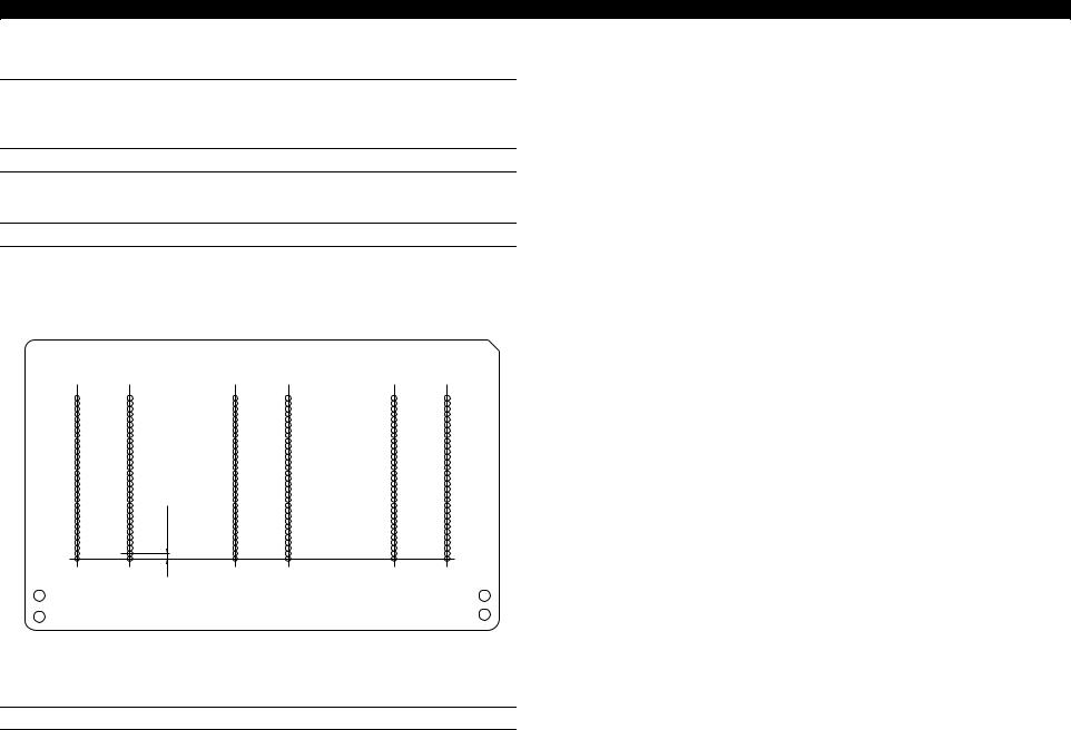
NOZZLE CONFIGURATION
o |
Black: |
32 nozzle |
o |
Color: |
32 nozzle x 5 colors |
|
|
(Cyan, Magenta, Yellow, Light Cyan, Light Magenta) |
Black |
Cyan |
Light |
Magenta |
Light |
Yellow |
|
Cyan |
Magenta |
|||||
|
|
|
|
#32 
4 / 360"
#1
nozzle
Figure 1-2. Nozzle Configuration (Seen from the Back of the Head)
PRINTING DIRECTION
o |
Bi-direction with logic seeking |
|
|
|
|
|
|
|
|
|
|
|
|
|
|
|
|
|
Revision A |
|
|
|
|
|
|
|
|
|
|
|
|
|
|
|
|||||
PRINTING SPEED AND PRINTABLE COLUMNS |
|
|
|
|
||||||||||||||
|
|
|
|
|
|
|
|
|
|
|
|
|
|
|
|
|
||
o |
Character mode: |
|
Refer to the table below. |
|
|
|
|
|||||||||||
|
|
Table 1-1. Printing Speed (Character Mode) |
||||||||||||||||
|
|
|
|
|
|
|
|
|
|
|
|
|
|
|
|
|
||
|
|
|
|
|
Character Pitch |
|
|
Printable Columns |
|
|
LQ speed |
|||||||
|
|
|
|
|
|
|
|
|
|
|
|
|
|
|
|
|
|
|
|
|
Stylus Photo 720 |
|
|
10 CPI (Pica) |
|
|
|
|
80 |
|
|
200 CPS** |
|||||
|
|
|
|
|
|
|
|
|
|
|
|
|
|
|
|
|
||
|
Stylus Photo EX3 |
|
|
10 CPI (Pica) |
|
|
|
|
114 |
|
|
200 CPS** |
||||||
|
|
|
|
|
|
|
|
|
|
|
|
|
|
|||||
NOTE: These figures are not described in the user’s guide. |
|
|
|
|
||||||||||||||
|
|
** This value is the speed of normal-dot printing. |
|
|
|
|
||||||||||||
o |
Raster graphics mode: |
Refer to the table below. |
|
|
|
|
||||||||||||
|
|
Table 1-2. Printing Speed (Raster Graphics Mode) |
||||||||||||||||
|
|
|
|
|
|
|
|
|
|
|
|
|
|
|
||||
|
|
|
|
|
Horizontal |
|
|
Printable |
|
Available |
|
|
CR Speed |
|
||||
|
|
|
|
|
Resolution |
|
|
|
Area |
|
Dot |
|
|
|
||||
|
|
|
|
|
|
|
|
|
|
|
|
|
||||||
|
|
|
|
|
|
|
|
|
|
|
|
|
|
|
|
|||
|
|
|
|
|
180 dpi |
|
|
|
8.26 inch |
|
1488 |
|
|
508mm/s (20 IPS) |
|
|||
|
|
|
|
|
|
|
|
|
|
|
|
|
|
|
|
|||
|
|
Stylus Photo 720 |
|
|
360 dpi |
|
|
|
8.26 inch |
|
2976 |
|
|
508mm/s (20 IPS) |
|
|||
|
|
|
|
|
|
|
|
|
|
|
|
|
|
|
|
|||
|
|
|
|
|
720 dpi |
|
|
|
8.26 inch |
|
5952 |
|
|
508mm/s (20 IPS) |
|
|||
|
|
|
|
|
|
|
|
|
|
|
|
|
|
|
|
|||
|
|
|
|
|
180 dpi |
|
|
|
11.46 inch |
|
2062 |
|
|
508mm/s (20 IPS) |
|
|||
|
|
|
|
|
|
|
|
|
|
|
|
|
|
|
|
|||
|
|
Stylus Photo EX3 |
|
|
360 dpi |
|
|
|
11.46 inch |
|
4125 |
|
|
508mm/s (20 IPS) |
|
|||
|
|
|
|
|
|
|
|
|
|
|
|
|
|
|
|
|||
|
|
|
|
|
720 dpi |
|
|
|
11.46 inch |
|
8250 |
|
|
508mm/s (20 IPS) |
|
|||
|
|
|
|
|
|
|
|
|
|
|
|
|
|
|
|
|
|
|
|
|
|
|
|
|
|
|
|
|
|
|
|
|
|
|
|
|
|
CONTROL CODE |
|
|
|
|
|
|
|
|
|
|
|
|
|
|
||||
|
|
|
|
|
|
|
|
|
|
|
|
|
|
|
|
|
|
|
o |
ESC/P Raster command |
|
|
|
|
|
|
|
|
|
|
|
|
|
||||
o |
EPSON Remote command |
|
|
|
|
|
|
|
|
|
|
|
|
|
||||
Product Description |
Basic Specification |
10 |

EPSON Stylus Photo 720 / EPSON Stylus Photo EX3
CHARACTER TABLES
o |
2 international character sets |
|
|
||
|
n |
PC437 (US, Standard Europe) |
|
|
|
|
n |
PC850 (Multilingual) |
|
|
|
|
|
|
|
||
TYPEFACE |
|
|
|
||
|
|
|
|
|
|
o |
Bitmap LQ font |
|
|
|
|
|
n |
EPSON Courier 10 CPI |
|
|
|
1.2.2 |
Paper Feed specification |
|
|
||
o |
Feeding Method: |
Friction feed with ASF |
|
||
o |
Paper path: |
Cut-sheet |
ASF (Top entry Front out) |
||
o |
Feed speed: |
10.16mm feed: |
|
110ms |
|
|
|
|
Continuous feed: |
114.3mm/s |
|
1.2.3 |
Input Data Buffer |
|
|
||
o |
Buffer: |
256 Kbytes |
|
|
|
Revision A
1.2.4 |
Electric Specification |
|
|
o |
120V version |
|
|
|
n |
Rated voltage: |
AC 100V |
|
n |
Input voltage range: |
AC 99 -132V |
|
n |
Rated frequency range: |
50 - 60Hz |
|
n |
Input frequency range: |
49.5-60.5 Hz |
|
n |
Rated current: |
0.4A (Max. TBD) |
|
n |
Power consumption: |
Approx.18W (ISO10561 Letter pattern) |
|
|
|
Approx. 2.5W in standby mode |
|
|
|
Energy Star compliant |
|
n |
Insulation Resistance: |
10 M ohms min. |
|
|
|
(between AC line and chassis, DC 500V) |
|
n |
Dielectric: |
AC 1000 V rms. 1 minute or |
|
|
|
AC 1200 V rms. 1 second |
|
|
|
(between AC line and chassis) |
o |
220-240V version |
|
|
|
n |
Rated voltage: |
AC 220 - 240V |
|
n |
Input voltage range: |
AC 198 - 264V |
|
n |
Rated frequency range: |
50 - 60Hz |
|
n |
Input frequency range: |
49.5-60.5 Hz |
|
n |
Rated current: |
0.2A (Max. TBD) |
|
n |
Power consumption: |
Approx.18W (ISO10561 Letter pattern) |
|
|
|
Approx. 2.5W in standby mode |
|
|
|
Energy Star compliant |
|
n |
Insulation Resistance: |
10 M ohms min. |
|
|
|
(between AC line and chassis, DC 500V) |
|
n |
Dielectric: |
AC 1500 V rms. 1 minute |
|
|
|
(between AC line and chassis) |
Product Description |
Basic Specification |
11 |
EPSON Stylus Photo 720 / EPSON Stylus Photo EX3
1.2.5 Environmental Conditions
o |
Temperature |
10 to 35°C*3 |
|
Operating: |
|
|
Non-operating: |
-20 to 40°C*1 |
|
|
1 month at 40°C, 120 hours at 60°C |
o |
Humidity |
|
|
Operating: |
20 to 80% RH*2,*3 |
|
Non-operating: |
5 to 85% RH*1,*2 |
o |
Resistance to shock |
|
|
Operating: |
1G, within 1ms |
|
Non-operating: |
2G, within 2ms*1 |
o |
Resistance to vibration |
|
|
Operating: |
0.15G |
|
Non-operating: |
0.50G*1 |
NOTE: *1: with shipment container. *2: without condensation.
*3: The environmental condition should be within the range shown in the figure below.
(%) |
|
|
|
80 |
|
|
|
55 |
|
|
|
20 |
|
|
|
10 |
27 |
35 |
(”C) |
|
|
tmphumid |
|
Figure 1-3. Environmental Condition
Revision A
1.2.6 |
Reliability |
|
|
|
o |
Total print volume: |
10,000 pages (A4, Letter) |
||
o |
Print Head Life: |
3 billion dots / nozzle |
||
|
|
|
Or 5 years at the normal temperature |
|
|
|
|
(Whichever comes first.) |
|
1.2.7 Safety Approvals |
|
|
||
o |
120V version: |
|
|
|
|
n |
Safety Standards: |
UL1950 |
|
|
|
|
CSA22.2 No.950 |
|
|
n |
EMI: |
FCC part15 subpart B class B |
|
|
|
|
CSA C108.8 class B |
|
o |
220 - 240V version: |
|
|
|
|
n |
Safety Standards: |
EN 60950 (VDE) |
|
|
n |
EMI: |
EN 55022 (CISPR Pub. 22) class B |
|
|
|
|
AS/NZS 3548 class B |
|
1.2.8 |
Acoustic Noise |
|
|
|
o |
Level: |
Approx. 47dB (A) (According to ISO7779) |
||
1.2.9 CE Marking |
|
|
||
220-240V version |
|
|
||
o |
Low Voltage Directive 73/23/EEC: |
EN60950 |
||
o |
EMC Directive 89/336/EEC: |
|
EN55022 class B |
|
|
|
|
|
EN61000-3-2 |
|
|
|
|
EN61000-3-3 |
|
|
|
|
EN50082-1 |
IEC801-2
IEC801-3
IEC801-4
Product Description |
Basic Specification |
12 |

EPSON Stylus Photo 720 / EPSON Stylus Photo EX3 |
Revision A |
1.3 Interface Specification
This printer has IEEE-1284 parallel interface and USB interface as standard.
1.3.1 IEEE-1284 Parallel I/F (Forward Channel)
Forward channel is the mode to transfer the ordinary printing command to the printer side from the PC side.
Table 1-3. Parallel I/F Specification (F-Channel)
Item |
|
Specification |
|
|
|
Transmission mode |
|
8bit parallel |
|
|
|
Synchronization |
|
By STROBE pulse supplied from the external |
|
|
|
Handshaking |
|
By BUSY and ACKNLG signal |
|
|
|
Signal Level |
|
TTL level (IEEE-1284-Level 1 device) |
|
|
|
Adaptable connector |
|
36 pin 57-30360 (amphenol) or equivalent |
|
|
|
NOTE: I/F cable is recommended to be in minimum length.
The connector pin assignment is described below. For these signals described in the table, use the twist pair wire and connect the return side to the signal GND.
Table 1-4. Connector Pin Assignment and Signals (F-Channel)
Pin No. |
|
Return |
|
Signal |
|
From |
|
Function Description |
|
GND Pin |
|
Name |
|
|
|||
|
|
|
|
|
|
|
||
|
|
|
|
|
|
|
|
|
|
|
|
|
|
|
|
|
The strobe pulse for the printer to read data. |
1 |
|
19 |
|
-STROBE |
|
PC |
|
Pulse width requires min. 0.5µs (500ns). |
|
|
|
|
High at normal condition. Receives data after |
||||
|
|
|
|
|
|
|
|
|
|
|
|
|
|
|
|
|
shifting Low. |
|
|
|
|
|
|
|
|
|
2-9 |
|
20-27 |
|
Data0-7 |
|
PC |
|
The DATA 1 through DATA8 signals |
|
|
|
|
represent data bits 1-8, respectively. |
||||
|
|
|
|
|
|
|
|
|
|
|
|
|
|
|
|
|
|
|
|
|
|
|
|
|
|
A low signal indicates the printer can accept |
10 |
|
28 |
|
-ACKNLG |
|
Printer |
|
data. Pulse width is 0.5 (default) or can be set |
|
|
|
|
|
|
|
|
at 2µs. |
|
|
|
|
|
|
|
|
|
Table 1-4. Connector Pin Assignment and Signals (F-Channel)
Pin No. |
|
Return |
|
Signal |
|
From |
|
Function Description |
|
GND Pin |
|
Name |
|
|
|||
|
|
|
|
|
|
|
||
|
|
|
|
|
|
|
|
|
|
|
|
|
|
|
|
|
A high signal indicates that the printer cannot |
|
|
|
|
|
|
|
|
receive data. The signal becomes high under |
11 |
|
29 |
|
BUSY |
|
Printer |
|
the condition below; |
|
|
|
|
-Receiving data. |
||||
|
|
|
|
|
|
|
|
|
|
|
|
|
|
|
|
|
-Error. |
|
|
|
|
|
|
|
|
-Other I/F receiving data. |
|
|
|
|
|
|
|
|
|
12 |
|
28 |
|
PE |
|
Printer |
|
A high signal indicates paper-out error. |
|
|
|
|
|
|
|
|
|
13 |
|
28 |
|
SLCT |
|
Printer |
|
Always at high level. Pulled up to +5V via |
|
|
|
|
1.0KΩ resistor. |
||||
|
|
|
|
|
|
|
|
|
|
|
|
|
|
|
|
|
|
14 |
|
30 |
|
-AFXT |
|
PC |
|
Not used. |
|
|
|
|
|
|
|
|
|
31 |
|
30 |
|
-INIT |
|
PC |
|
The printer is initialized by the width of min. |
|
|
|
|
50µs Low pulse input. |
||||
|
|
|
|
|
|
|
|
|
|
|
|
|
|
|
|
|
|
32 |
|
29 |
|
-ERROR |
|
PC |
|
A low signal indicates printer error condition. |
|
|
|
|
|
|
|
|
|
36 |
|
30 |
|
-SLIN |
|
- |
|
Not used. |
|
|
|
|
|
|
|
|
|
18 |
|
- |
|
Logic H |
|
- |
|
Always at high level. Pulled up to +5V via |
|
|
|
|
3.9KΩ resistor. |
||||
|
|
|
|
|
|
|
|
|
|
|
|
|
|
|
|
|
|
35 |
|
- |
|
+5V |
|
- |
|
Always at high level. Pulled up to +5V via |
|
|
|
|
1.0KΩ resistor. |
||||
|
|
|
|
|
|
|
|
|
|
|
|
|
|
|
|
|
|
17 |
|
- |
|
Chassis |
|
- |
|
Printer chassis GND. |
|
|
|
|
|
|
|
|
|
16, 33 |
|
- |
|
GND |
|
- |
|
Twist pair return GND. |
19-30 |
|
|
|
|
||||
|
|
|
|
|
|
|
|
|
|
|
|
|
|
|
|
|
|
15, 34 |
|
- |
|
NC |
|
- |
|
Not used. |
|
|
|
|
|
|
|
|
|
1.3.2 IEEE-1284 Parallel I/F (Reverse Channel)
Reverse channel is used to transfer the information data from the printer side to the PC side.
Product Description |
Interface Specification |
13 |

EPSON Stylus Photo 720 / EPSON Stylus Photo EX3
Table 1-5. Parallel I/F Specification (R-Channel)
Item |
|
Specification |
|
|
|
Transmission mode |
|
IEEE-1284 nibble mode |
|
|
|
Synchronization |
|
Comply with the IEEE-1284 specification |
|
|
|
Handshaking |
|
Comply with the IEEE-1284 specification |
|
|
|
Logic Level |
|
TTL level (IEEE-1284-Level 1 device) |
|
|
|
Data trans. timing |
|
Comply with the IEEE-1284 specification |
|
|
|
Extensibility request data |
|
The printer responds affirmatively when the extensibility request |
|
|
values are 00H or 04H; |
|
|
00H: Request Nibble Mode Reverse Channel Transfer. |
|
|
04H: Request Device ID; |
|
|
Return Data Using Nibble Mode Reverse Channel Transfer |
|
|
|
Revision A
o |
Device ID |
|
|
n |
When IEEE-1284.4 protocol is effective: |
|
|
[00H] [5AH] |
|
|
MFG: EPSON; |
|
|
CMD: ESCPL2, BDC, D4; |
|
|
MDL: Stylus[SP]Photo[SP]720;*1 |
|
|
CLS: PRINTER; |
|
|
DES: EPSON[SP]Stylus[SP]Photo[SP]720;*1 |
|
n |
When IEEE1284.4 protocol is NOT effective: |
|
|
[00H] [57H] |
|
|
MFG: EPSON; |
CMD: ESCPL2, BDC;
MDL: Stylus[SP]Photo[SP]720;*1
CLS: PRINTER;
DES: EPSON[SP]Stylus[SP]Photo[SP]720;*1
Note: *1 For Stylus Photo EX3, MDL: Stylus[SP]Photo[SP]EX3;
DES: EPSON[SP]Stylus[SP]Photo[SP]EX3, respectively.
The connector pin assignment is described in the table below. For these signals described in the table, use the twist pair wire and connect the return side to the signal GND.
Table 1-6. Connector Pin Assignment and Signals (F-Channel)
Pin No. |
|
Return |
|
Signal Name |
|
From |
|
Function Description |
|
GND Pin |
|
|
|
||||
|
|
|
|
|
|
|
|
|
|
|
|
|
|
|
|
|
|
1 |
|
19 |
|
HostClk |
|
PC |
|
Host clock signal. |
|
|
|
|
|
|
|
|
|
2-9 |
|
20-27 |
|
Data1-8 |
|
PC |
|
The DATA 1 through DATA8 signals |
|
|
|
|
represent data bits 1-8 respectively. |
||||
|
|
|
|
|
|
|
|
|
|
|
|
|
|
|
|
|
|
10 |
|
28 |
|
PtrClk |
|
Printer |
|
Printer clock signal. |
|
|
|
|
|
|
|
|
|
11 |
|
29 |
|
PtrBusy/ |
|
Printer |
|
Printer busy signal and reverse channel |
|
|
DataBit-3,7 |
|
|
transfer data bit 3 or 7. |
|||
|
|
|
|
|
|
|
||
|
|
|
|
|
|
|
|
|
12 |
|
28 |
|
AckDataReq/ |
|
Printer |
|
Acknowledge data request signal and |
|
|
DataBit-2,6 |
|
|
reverse channel transfer data bit 2 or 6. |
|||
|
|
|
|
|
|
|
||
|
|
|
|
|
|
|
|
|
13 |
|
28 |
|
Xflag/DataBit- |
|
Printer |
|
X-flag signal and reverse channel |
|
|
1,5 |
|
|
transfer data bit 1 or 5. |
|||
|
|
|
|
|
|
|
||
|
|
|
|
|
|
|
|
|
Product Description |
Interface Specification |
14 |

EPSON Stylus Photo 720 / EPSON Stylus Photo EX3 |
Revision A |
Table 1-6. Connector Pin Assignment and Signals (F-Channel)
Pin No. |
|
Return |
|
Signal Name |
|
From |
|
Function Description |
|
GND Pin |
|
|
|
||||
|
|
|
|
|
|
|
|
|
|
|
|
|
|
|
|
|
|
14 |
|
30 |
|
HostBusy |
|
PC |
|
Host busy signal. |
|
|
|
|
|
|
|
|
|
31 |
|
30 |
|
-INIT |
|
PC |
|
Not used. |
|
|
|
|
|
|
|
|
|
32 |
|
29 |
|
-DataAvail/ |
|
Printer |
|
Data available signal and reverse channel |
|
|
DataBit-0,4 |
|
|
transfer data bit 0 or 4. |
|||
|
|
|
|
|
|
|
||
|
|
|
|
|
|
|
|
|
36 |
|
30 |
|
1284-Active |
|
PC |
|
1284 active signal. |
|
|
|
|
|
|
|
|
|
18 |
|
- |
|
Logic H |
|
Printer |
|
Pulled up to +5V via 3.9K ohm resistor. |
|
|
|
|
|
|
|
|
|
35 |
|
- |
|
+5V |
|
Printer |
|
Pulled up to +5V via 3.3 K ohm resistor. |
|
|
|
|
|
|
|
|
|
17 |
|
- |
|
Chassis |
|
- |
|
Printer chassis GND. |
|
|
|
|
|
|
|
|
|
16, 33 |
|
- |
|
GND |
|
- |
|
Twist pair return GND. |
19-30 |
|
|
|
|
||||
|
|
|
|
|
|
|
|
|
|
|
|
|
|
|
|
|
|
15, 34 |
|
- |
|
NC |
|
- |
|
Not used. |
|
|
|
|
|
|
|
|
|
Following lists “Notes” when using the parallel interface.
o |
“Return GND pin” in the table means twist pair return and is connected to the |
|
signal GND level. |
|
For each signal, use the twist pair wire and connect the return side. |
|
Also, these cables are shielded wires and it is effective means to connect to each |
|
chassis GND in the center machine and printer for electrostatic noise. |
o |
Conditions for interface are all based on TTL level. Rise and fall time should be |
|
within 0.2 s. |
o |
Refer to the timing chart for transmission timing of each signals. |
o |
Do not perform data transmission ignoring -ACK or BUSY signals. (Perform the |
|
data transmission after confirming that either -ACK or BUSY signal is Low) |
o |
It is possible to perform the printing test including interface circuit without using |
|
external equipment when 8-bit data signal (2-9 pin) is set to appropriate character |
|
code (against GND, Open=”1”, Short=”0”) and connect then forcefully to -ACK |
|
and -STRB. However, to perform this, “I/F selection” of EEPROM must be set to |
|
“Auto”. Also, IEEE-1284.4 packet mode must be set Off. |
The figure below shows the timing chart of the parallel interface.
DATA |
|
|
|
|
|
|
Data byte n |
|
Data byte n+1 |
||
|
|
|
|
|
|
thold
/STROBE
tsetup |
tstb |
|
tnext |
BUSY
tready tbusy
/ACKNLG
treply |
tack |
tnbusy |
timechart
Figure 1-4. Timing Chart
On the above timing chart, Tact rated period is shown below.
|
Table 1-7. tact Rated Period |
||
Parallel I/F Mode |
|
|
Tact Rated Period |
|
|
|
|
High speed (default) |
|
|
0.5 s |
|
|
|
|
Normal speed |
|
|
2 s |
|
|
|
|
Product Description |
Interface Specification |
15 |
EPSON Stylus Photo 720 / EPSON Stylus Photo EX3 |
Revision A |
1.3.3 |
USB (Universal Serious Bus) |
|||||||||||||
Following shows specification. |
|
|
|
|
|
|
|
|
||||||
o |
Standard: |
|
|
|
|
|
|
|
|
|||||
|
|
n |
Universal Serial Bus Specifications Revision 1.0 |
|||||||||||
|
|
n |
Universal Serial Bus Device Class Definition for Printing Devices version 1.1 |
|||||||||||
o |
Bit rate: |
|
|
12Mbyte (Full Speed Device) |
||||||||||
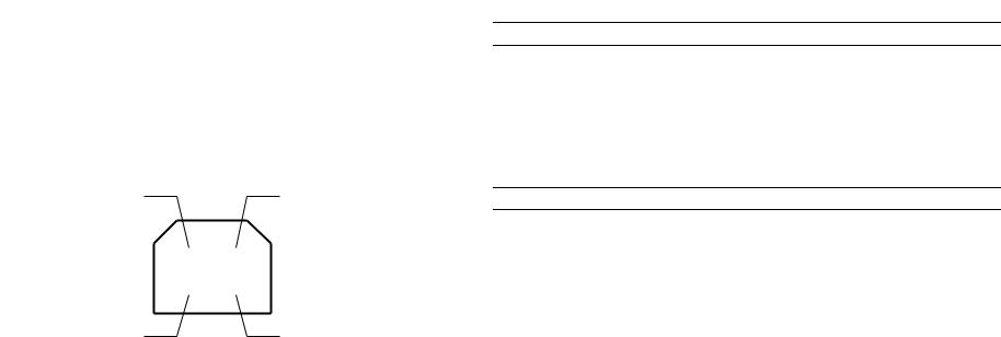
o |
Data encoding: |
|
|
NRZI |
||||||||||
o |
Adaptable connector: |
|
|
USB Series B |
||||||||||
o |
Recommended cable length: |
|
|
max. 2 meters |
||||||||||
|
|
|
|
Table 1-8. Connector Pin Assignment and Signals |
||||||||||
|
|
|
|
|
|
|
|
|
|
|
|
|
|
|
|
|
Pin. |
|
Signal Name |
|
|
I/Out |
|
|
|
|
|
Function Description |
|
|
|
No |
|
|
|
|
|
|
|
|
||||
|
|
|
|
|
|
|
|
|
|
|
|
|
|
|
|
|
|
|
|
|
|
|
|
|
|
|
|
|
|
|
|
1 |
|
VCC |
|
|
-- |
|
|
|
Cable power. Maximum power consumption |
|||
|
|
|
|
|
|
|
|
is 2mA. |
||||||
|
|
|
|
|
|
|
|
|
|
|
||||
|
|
|
|
|
|
|
|
|
|
|
|
|
|
|
|
|
2 |
|
-Data |
|
|
I/O |
|
|
Data |
||||
|
|
|
|
|
|
|
|
|
|
|
|
|
|
|
|
|
3 |
|
+Data |
|
|
I/O |
|
|
Data. Pull up to +3.3V via 1.5K ohm resistor. |
||||
|
|
|
|
|
|
|
|
|
|
|
|
|
|
|
|
|
4 |
|
Ground |
|
|
-- |
|
|
|
Cable ground. |
|||
|
|
|
|
|
|
|
|
|
|
|
|
|
|
|
|
|
|
|
|
|
|
Pin #2 |
|
|
|
|
|
Pin #1 |
|
|
|
|
|
|
|
|
|
|
|
|
|
|
|
|
|
|
|
|
|
|
|
|
|
|
|
|
|
|
|
|
|
|
|
|
|
|
|
|
|
|
|
|
|
|
|
|
|
|
|
|
|
|
|
|
|
|
|
|
|
Pin #3 |
Pin #4 |
usb
Figure 1-5. USB Interface Port
1.3.4 Miscellanea
1.3.4.1 Preventing Hosts from Data Transfer Time-out
Generally, hosts abandon data transfer to peripherals when a peripheral is in busy state for dozens of seconds continuously. To prevent hosts from acting this kind of time-out, when the open space of input buffer becomes 1024 byte, the printer receives data per certain period of time (1 second) and avoid BUSY state continues for a long time. The printer will be in busy state continuously when the input buffer finally gets full. This operation is not performed while communicating by IEEE1284.4 protocol.
1.3.4.2 Interface Selection
IEEE-1284 parallel interface and USB interface is switched by auto select function. The following explains the conditional shift of the I/F auto select function and the operations when specific interface is set.
AUTOMATIC SELECTION
In this automatic interface selection mode, the printer is initialized to the idle state scanning which interface receives data when it is powered on. Then the interface that receives data first is selected. When the host stops data transfer and the printer is in the stand-by state for the seconds, the printer is returned to the idle state. As long as the host sends data or the printer interface is in the busy state, the selected interface is let as is.
INTERFACE STATE AND INTERFACE SELECTION
o |
When the parallel interface is not selected, the interface became to the busy state. |
|
When the printer is initialized or returned to the idle state, the parallel interface |
|
became to the ready state. Caution that the interrupt signal such as the -INIT signal |
|
on the parallel interface is not effective while the inter face is not selected. |
Product Description |
Interface Specification |
16 |
EPSON Stylus Photo 720 / EPSON Stylus Photo EX3 |
Revision A |
1.3.4.3 IEEE 1284.4 protocol
The packet protocol described by IEEE1284.4 standard always a device to carry on multiple exchanges or conversations which contain data and/or control information with another device at the same time across a single point-to-point link. The protocol is not, however, a device control language. It does provide basic transport-level flow control and multiplexing services. The multiplexed logical channels are independent of each other and blocking of one has no effect on the others. The protocol operate over IEEE1284.
o
Auto
An initial state is compatible interface and starts IEEE1284.4 communication when the magic strings (1284.4 synchronous commands) are received.
o
On
An initial state is IEEE 1284.4 communication and data that received it by the time it is able to take synchronization by magic string (1284.4 synchronous commands) is discarded.
o
Off
An initial state is compatible interface and never starts IEEE1284.4 communication even if the magic strings (1284.4 synchronous commands) are received.
For parallel I/F, regardless of the factory default setting, after initial ink charge operation, the setting of the EEPROM must be set to “AUTO”. The change in this setting will be effective when the power is back on after the initial ink charge operation.
Product Description |
Interface Specification |
17 |
EPSON Stylus Photo 720 / EPSON Stylus Photo EX3 |
Revision A |
1.4 Control Specification
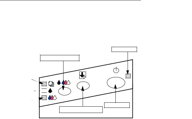
1.4.1 Control Panel
The control panel is at the front right of the printer and has 2 non-lock type push switches and 1 lock type switch and 4 LEDs. The appearance of the control panel differs between Stylus Photo 720 and Stylus Photo EX3, but the number of buttons and LEDs is the same. So, this section explains names of the buttons using the Stylus Photo 720 control panel.
Power LED
Ink Maintenance Button
Paper Check LED
Black Ink End LED 


Color Ink End LED
Power Button
Load/ Eject Button
Figure 1-6. Control Panel
1.4.2 Control Switches
Since this printer does not have so many switches, each button has several functions. The tables below show their functions and how to enter those functions for each button.
Table 1-9. Panel Functions in Normal State
Button |
|
Function |
|
|
|
Load/Eject |
|
Load or eject paper |
(Less than 2 seconds) |
|
When the print head is at the ink replacement position, it returns to |
|
|
the home position. |
|
|
|
Load/ Eject |
|
Start the ink cartridge replacement sequence. |
(for 3 seconds) |
|
|
|
|
|
Ink maintenance |
|
Start cleaning the print head. |
(for 3 seconds) |
|
In the condition of “Ink Low”, “Ink End” or “No Ink Cartridge”, |
|
|
start the ink cartridge replacement sequence. |
|
|
|
Ink maintenance |
|
When the print head is at the ink replacement position, it returns to |
(Less than 2 seconds) |
|
the home position. |
|
|
|
Product Description |
Control Specification |
18 |

EPSON Stylus Photo 720 / EPSON Stylus Photo EX3
Table 1-10. Panel Function with Turning the Power On *Note
Button |
|
Function |
|
|
|
Load/Eject |
|
Start status-printing.*1 |
|
|
Print “Firmware version”→ “CPU Mask version”→ “Waste |
|
|
ink counter”→ “Code page setting”→ “Nozzle check pattern”. |
|
|
|
Ink maintenance |
|
Code page.selection/ Parallel I/F IEEE 1284.4 setting (See |
|
|
Section 1.4.2.1) |
|
|
|
Load/Eject |
|
Start special setting mode. |
+ |
|
(See Table 1-13) |
Ink maintenance |
|
|
|
|
|
NOTE: Turning the power on = to turn on the printer power while specified button is pressed down.
*1: Printer performs the following according to the value of 1BH in EEPROM.
Table 1-11. EEPROM 1BH Data and Function W
Bit 7, Bit 6 |
|
Action |
|
|
|
00 |
|
Print firmware version, ink counter, selected code page and nozzle |
|
|
|
11 |
|
check pattern. |
|
|
|
|
|
|
01 |
|
Start hex-dump printing. |
|
|
|
10 |
|
Start self-test printing. |
|
|
|
Revision A
1.4.2.1 Code Page Selection/ Parallel I/F IEEE1284.4 Setting
On this setting mode, you can select code page table (PC437 or PC850) and parallel I/F IEEE1284.4 mode (ON, AUTO, OFF).
o |
Code Page Selection |
You can select the code table PC437 or PC850 by the following panel operation.
1.Turn on the power while pressing the maintenance button.
2.Paper check LED starts blinking.
3.When you see the paper check LED starts blinking, release maintenance button.
4.After 2 seconds, the code page setting will be indicated by maintenance LED. See the table below.
Table 1-12. Code Page Setting
Code page before this |
|
Code page after this |
|
LED Indication |
function is performed. |
|
function is performed. |
|
|
|
|
|
||
|
|
|
|
|
PC437 |
|
PC850 |
|
Ink END (Color) ON |
|
|
|
|
|
PC850 |
|
PC437 |
|
Ink END (Black) ON |
|
|
|
|
|
NOTE: You can check current code page by status print.
Product Description |
Control Specification |
19 |

EPSON Stylus Photo 720 / EPSON Stylus Photo EX3 |
Revision A |
1.4.2.2 Special Setting Mode
You can go to the special setting mode by the following operations.
1.Turn on the power while pressing the Load/ Eject button and ink maintenance button.
2.Paper check LED starts blinking. (3 seconds)
3.While the paper check LED is blinking (3 seconds), press the appropriate button. See Table 1-13.
n |
When maintenance error (protection counter over flow) is |
|
happened, if you clear the error by this operation, be sure to |
|
replace the waste ink absorber. |
n |
Whenever you replaced the waste ink counter (even when ink |
|
maintenance error has not occurred), be sure to perform the |
|
counter reset by this operation. |
Table 1-13. Special Settings Mode |
||
|
|
|
Buttons |
|
Function |
|
|
|
Load/Eject |
|
Initialize EEPROM and reset timer IC. |
|
|
This operation will reset the following items: |
|
|
• Interface selection (04H) |
|
|
• CL time (68/ 69H) |
|
|
• Power OFF time (6C/ 6DH) |
|
|
|
|
|
Reset the ink overflow counter. |
Cleaning |
|
This operation will reset the following items: |
(Pressed for 10 seconds) |
|
• Ink counter A0 (5C/ 5DH) |
|
|
• Ink counter A80 (5E/ 5FH) |
|
|
|
NOTE: Hold the button pressed for 10 seconds.
1.4.3 LED Indications
See the table below for more detailed LED indications. Since LED indicates the various errors and current printer operations, LED indications enable to find out the proper repair operation.
Table 1-14. Printer Status displayed on the control panel
|
|
|
|
Indicators |
|
|
|
|
||
Printer Status |
|
|
|
|
|
|
|
|
|
|
|
Power |
|
Paper |
|
Ink End |
|
Ink end |
|
Priority |
|
|
|
|
|
|
|
|||||
|
|
|
Check |
|
(Black) |
|
(Color) |
|
||
|
|
|
|
|
|
|
|
|||
|
|
|
|
|
|
|
|
|
|
|
Power on condition |
|
On |
|
--*3 |
|
-- |
|
-- |
|
9 |
|
|
|
|
|
|
|
|
|
|
|
Ink sequence |
|
Blink |
|
-- |
|
-- |
|
-- |
|
6 |
|
|
|
|
|
|
|
|
|
|
|
Ink cartridge exchange mode |
|
Blink |
|
-- |
|
-- |
|
-- |
|
5 |
|
|
|
|
|
|
|
|
|
|
|
Data processing |
|
Blink |
|
-- |
|
-- |
|
-- |
|
8 |
|
|
|
|
|
|
|
|
|
|
|
Paper check*1 |
|
-- |
|
On |
|
-- |
|
-- |
|
4 |
|
|
|
|
|
|
|
|
|
|
|
Paper jam*1 |
|
-- |
|
Blink |
|
Off |
|
Off |
|
3 |
No ink cartridge or Ink end |
|
-- |
|
-- |
|
On |
|
-- |
|
7 |
(black)*1 |
|
|
|
|
|
|||||
|
|
|
|
|
|
|
|
|
|
|
|
|
|
|
|
|
|
|
|
|
|
No ink cartridge or Ink end |
|
-- |
|
-- |
|
-- |
|
On |
|
7 |
(color)*1 |
|
|
|
|
|
|||||
|
|
|
|
|
|
|
|
|
|
|
Ink level low (black) |
|
-- |
|
-- |
|
Blink |
|
-- |
|
7 |
|
|
|
|
|
|
|
|
|
|
|
Ink level low (color) |
|
-- |
|
-- |
|
-- |
|
Blink |
|
7 |
|
|
|
|
|
|
|
|
|
|
|
|
|
|
|
On |
|
On |
|
On |
|
|
EEPROM and Timer IC reset*2 |
|
-- |
|
(for 1 |
|
(for 1 |
|
(for 1 |
|
-- |
|
|
|
|
second) |
|
second) |
|
second) |
|
|
|
|
|
|
|
|
|
|
|
|
|
Maintenance Request |
|
Blink |
|
Blink |
|
Blink |
|
Blink |
|
2 |
|
|
|
|
|
|
|
|
|
|
|
Fatal Error*1 |
|
Blink |
|
Blink |
|
On |
|
On |
|
1 |
|
|
|
|
|
|
|
|
|
|
|
NOTE: *1 For error condition, refer to “Fatal Error” under the “Errors” on page 21.
*2 EEPROM clear does not mean to clear all address in EEPROM. (See “Special Settings Mode” on page 20)
*3 -- in the table above means no change.
Product Description |
Control Specification |
20 |
EPSON Stylus Photo 720 / EPSON Stylus Photo EX3 |
Revision A |
1.4.4 Initialization
The printer have 3 types of initialization. The initialization operations executed by each initialization method are described below.
o |
Hardware Initialization |
|
|
This printer initializes itself when it is turned on. |
|
|
On this initialization, following actions are performed. |
|
|
n |
Initialize printer mechanism |
|
n |
Clear the input data buffer |
|
n |
Clear the print buffer |
|
n |
Set default values |
o |
Software initialization |
|
|
Initialization command, “ESC@” also initializes the printer. |
|
|
On this initialization, following actions are performed. |
|
|
n |
Clear the print buffer |
|
n |
Set default values |
o |
Panel initialization |
|
|
This printer initializes itself when it is turned off and is turned on again within 10 |
|
|
seconds, or when it recognizes the -INIT signal input. |
|
|
On this initialization, following actions are performed. |
|
|
n |
Cap the print head (Mechanism initialization is not performed.) |
|
n |
Eject paper |
|
n |
Clear the input buffer |
|
n |
Clear the print buffer |
|
n |
Set default values |
1.4.5 Errors
o |
Ink Out |
|
When the printer almost runs out the ink of any one color, it warns ink-low and |
|
keeps printing. When the printer runs out the whole ink of any one color, it stops |
|
printing and indicates ink-out error. User is requested to install a new ink-cartridge |
|
in this state. A ink-cartridge once taken out should never used again. Re- |
|
installation of the cartridge not filled fully upsets the ink level detection and may |
|
cause a serious problem in the print head as a result. |
o |
Paper out |
|
When the printer fails to load a sheet, it goes paper out error. |
o |
Paper jam |
|
When the printer fails to eject a sheet, it goes paper jam error. |
o |
No ink-cartridge |
|
When the printer detects that the ink-cartridge comes off, it goes no ink-cartridge |
|
error. |
o |
Maintenance request |
|
When the total quantity of ink wasted through the cleaning and flushing reaches to |
|
the limit, the printer indicates this error and stops. The absorber in the printer |
|
enclosure is needed to be replaced with new one by a service person. |
o |
Fatal errors |
|
Carriage control error or CG access error. |
Product Description |
Control Specification |
21 |
EPSON Stylus Photo 720 / EPSON Stylus Photo EX3
1.5 Paper
1.5.1 Paper handling
Do not perform reverse feed more than 9.5mm (0.38”).
1.5.2 Paper Specification
STYLUS PHOTO 720
o |
Cut Sheet |
|
|
|
n |
Paper Size: |
|
|
|
A4 (210 x 297 mm) |
|
|
|
Letter (216 x 279 mm) |
|
|
|
B5 (182 x 257 mm) |
|
|
|
Legal (216 x 356 mm) |
|
|
|
Statement (139.7 x 215.9 mm) |
|
|
|
Executive (184.2 x 266.7 mm) |
|
|
|
A5 (148 x 210 mm) |
|
|
|
A6 (105 x 148 mm) |
|
|
n |
Thickness: |
0.08mm to 0.11mm(0.003 to 0.004”) |
|
n |
Weight: |
64g/m2 to 90g/m2 (17lb to 24lb) |
|
n |
Paper quality: |
Exclusive paper, Bond paper, PPC |
o |
Transparency, Glossy paper |
||
|
n |
Size: |
|
|
|
A4 (210 x 297 mm) |
|
|
|
Letter (216 x 279 mm) |
|
|
n |
Thickness: |
0.075mm to 0.085mm(0.003 to 0.0033”) |
*Transparency printing is only available at normal temperature.
Revision A
o |
Envelope |
|
|
|
n |
Size: |
|
|
|
No.10 (241.3 mm x 104.8 mm) |
|
|
|
DL (220 mm x 110 mm) |
|
|
|
C6 (162 mm x 114 mm) |
|
|
n |
Thickness: |
0.16mm to 0.52mm(0.006 to 0.02”) |
|
n |
Weight: |
45g/m2 to 75g/m2 (12lb to 20lb) |
|
n |
Paper quality: |
Bond paper, Plain paper, Air mail |
*Envelope printing is only available at normal temperature.
*Keep the longer side of the envelope horizontally at setting.
o |
Index Card |
|
|
|
n |
Size: |
|
|
|
A6 (105 x 148 mm) |
|
|
|
A5 (148 x 210 mm) |
|
|
|
5x8” index card (127 x 203 mm) |
|
|
|
10x8” index card (254 x 203mm) |
|
|
n |
Thickness: |
0.23 mm(0.0091”) |
Product Description |
Paper |
22 |

EPSON Stylus Photo 720 / EPSON Stylus Photo EX3
STYLUS PHOTO EX3
Additional following items to the Stylus Photo 720 specification;
o |
Cut Sheet |
|
|
|
n |
Paper size: |
|
|
|
A3 (297 x 420 mm) |
|
|
|
Letter (216 x 279 mm) |
|
|
|
B5 (182 x 257 mm) |
|
|
|
Legal (216 x 356 mm) |
|
|
|
Statement (139.7 x 215.9 mm) |
|
|
|
Executive (184.2 x 266.7 mm) |
|
|
|
A5 (148 x 210 mm) |
|
|
|
A6 (105 x 148 mm) |
|
|
n |
Thickness: |
0.08mm to 0.11mm(0.003 to 0.004”) |
|
n |
Weight: |
64g/m2 to 90g/m2 (17lb to 24lb) |
|
n |
Paper quality: |
Exclusive paper, Bond paper, PPC |
o |
Transparency, Glossy paper |
||
|
n |
Size: |
|
|
|
A3 (297 x 420 mm) |
|
|
|
A4 (210 x 297 mm) |
|
|
|
Letter (216 x 279 mm) |
|
|
n |
Thickness: |
0.075mm to 0.085mm(0.003 to 0.0033”) |
*Transparency printing is only available at normal temperature.
o |
Envelope |
|
|
|
n |
Size: |
|
|
|
No.10 (241.3 mm x 104.8 mm) |
|
|
|
DL (220 mm x 110 mm) |
|
|
|
C6 (162 mm x 114 mm) |
|
|
n |
Thickness: |
0.16mm to 0.52mm(0.006 to 0.02”) |
|
n |
Weight: |
45g/m2 to 75g/m2 (12lb to 20lb) |
Revision A
n |
Paper quality: |
Bond paper, Plain paper, Air mail |
*Envelope printing is only available at normal temperature.
*Keep the longer side of the envelope horizontally at setting.
o |
Index Card |
|
|
|
n |
Size: |
|
|
|
A6 (105 x 148 mm) |
|
|
|
A5 (148 x 210 mm) |
|
|
|
5x8” index card (127 x 203 mm) |
|
|
|
10x8” index card (254 x 203mm) |
|
|
n |
Thickness: |
0.23 mm(0.0091”) |
Product Description |
Paper |
23 |
EPSON Stylus Photo 720 / EPSON Stylus Photo EX3 |
Revision A |
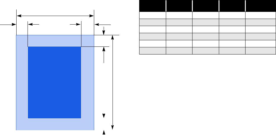
1.5.3 Printable Area
Table 1-15. Character Mode
o
Cut Sheet |
|
Paper Size |
LM (Left |
RM (Right |
TM (Top |
BM (Bottom |
|
|
Margin) min. |
Margin) min. |
Margin) min. |
Margin) min. |
|
|
|
|
||||
|
PW |
A4 |
3mm (0.12”) |
3mm (0.12”) |
3mm (0.12”) |
14 mm (0.54”) |
|
|
|||||
LM |
RM |
Letter |
3mm (0.12”) |
9mm (0.35”) |
3mm (0.12”) |
14 mm (0.54”) |
|
|
B5 |
3mm (0.12”) |
3mm (0.12”) |
3mm (0.12”) |
14 mm (0.54”) |
|
|
Legal |
3mm (0.12”) |
9mm (0.35”) |
3mm (0.12”) |
14 mm (0.54”) |
|
TM |
Statement |
3mm (0.12”) |
3mm (0.12”) |
3mm (0.12”) |
14 mm (0.54”) |
|
|
|||||
|
|
Exclusive |
3mm (0.12”) |
3mm (0.12”) |
3mm (0.12”) |
14 mm (0.54”) |
|
|
|
|
|
|
|
|
|
Table 1-16. Raster Graphics Mode |
|
|
||||
|
|
|
|
|
|
|
|
|
|
|
|
|
|
|
|
|
|
|
|
|
|
|
Paper Size |
|
LM (Left |
|
RM (Right |
|
TM (Top |
|
BM (Bottom |
|
|
|
|
|
|
|
|
Margin) min. |
|
Margin) min. |
|
Margin) min. |
|
Margin) min. |
|
|
|
|
|
|
|
|
|
|
|
|
|
||||
Printable Area |
|
|
PL |
|
|
|
|
|
|
|
|
|
|||
|
|
A4 |
|
3mm (0.12”) |
|
3mm (0.12”) |
|
3mm (0.12”) |
|
14 mm (0.54”) / |
|||||
|
|
|
|
|
|
|
|
|
|
|
3mm (0.12”)* |
||||
|
|
|
|
|
|
|
|
|
|
|
|
|
|
|
|
|
|
|
|
|
|
|
|
|
|
|
|
|
|
|
|
|
|
|
|
|
|
|
Letter |
|
3mm (0.12”) |
|
3mm (0.12”) |
|
3mm (0.12”) |
|
14 mm (0.54”) / |
|
|
|
|
|
|
|
|
|
|
|
3mm (0.12”)* |
||||
|
|
|
|
|
|
|
|
|
|
|
|
|
|
|
|
|
|
|
|
|
|
|
|
|
|
|
|
|
|
|
|
|
|
|
|
|
|
|
B5 |
|
3mm (0.12”) |
|
3mm (0.12”) |
|
3mm (0.12”) |
|
14 mm (0.54”) / |
|
|
|
|
|
|
|
|
|
|
||||||
|
|
|
|
|
|
|
|
|
|
|
3mm (0.12”)* |
||||
|
|
|
|
|
|
|
|
|
|
|
|
|
|
|
|
|
|
|
|
|
|
|
|
|
|
|
|
|
|
|
|
|
|
|
|
|
|
|
Legal |
|
3mm (0.12”) |
|
9mm (0.35”) |
|
3mm (0.12”) |
|
14 mm (0.54”) / |
|
|
|
|
|
|
|
|
|
|
||||||
|
|
|
|
|
|
|
|
|
|
|
3mm (0.12”)* |
||||
|
|
|
BM |
|
|
|
|
|
|
|
|
||||
|
|
|
|
|
|
|
|
|
|
|
|
||||
|
|
|
Statement |
|
3mm (0.12”) |
|
3mm (0.12”) |
|
3mm (0.12”) |
|
14 mm (0.54”) / |
||||
|
|
|
|
|
|
|
|
|
|
|
|||||
|
|
|
|
|
|
|
|
|
|
|
3mm (0.12”)* |
||||
|
|
|
|
|
|
|
|
|
|
|
|
|
|
|
|
|
|
|
|
|
|
|
|
|
|
|
|
|
|
|
|
|
|
|
|
|
|
|
Exclusive |
|
3mm (0.12”) |
|
3mm (0.12”) |
|
3mm (0.12”) |
|
14 mm (0.54”) / |
|
|
|
|
|
|
|
|
|
|
||||||
|
|
|
|
|
|
|
|
|
|
|
3mm (0.12”)* |
||||
Figure 1-7. Cut Sheet Printable Area |
|
|
|
|
|
|
|
|
|
|
|
|
|||
|
|
|
|
|
|
|
|
|
|
|
|
|
|||
|
|
|
|
|
|
|
|
|
|
|
|
|
|||
NOTE: * Bottom margin can be set up to 3mm at minimum when the paper length is designated with “ESC(S” command.) However, the printing quality is not guaranteed in the area ranging from 3mm to 14mm, from the form lower end. When the paper length is not designated, the bottom margin must be wider than 14 mm.
Product Description |
Paper |
24 |
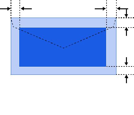
EPSON Stylus Photo 720 / EPSON Stylus Photo EX3 |
Revision A |
o |
Envelope |
|
|
LM |
RM |
|
|
TM |
|
|
Printableri t le Area |
|
|
BM |
Figure 1-8. Printable Area for Envelopes
Table 1-17. Envelope Margin
|
|
Left Margin |
|
Right Margin |
|
Top Margin |
|
Bottom Margin |
Size |
|
(minimum) |
|
(minimum) |
|
(minimum) |
|
(minimum) |
|
|
|
|
|
|
|
|
|
#10 |
|
3 mm (0.12”) |
|
28 mm (1.10”) |
|
3 mm (0.12”) |
|
14 mm (0.55”) |
|
|
|
|
|
|
|
|
|
DL |
|
3 mm (0.12”) |
|
7 mm (0.28”) |
|
3 mm (0.12”) |
|
14 mm (0.55”) |
|
|
|
|
|
|
|
|
|
C6 |
|
3 mm (0.12”) |
|
3 mm (0.12”) |
|
3 mm (0.12”) |
|
14 mm (0.55”) |
|
|
|
|
|
|
|
|
|
Product Description |
Paper |
25 |
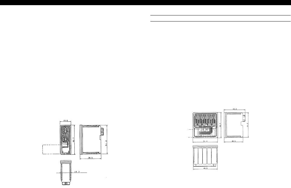
EPSON Stylus Photo 720 / EPSON Stylus Photo EX3
1.5.4 |
Ink Cartridge |
||
|
|||
INK CARTRIDGE (BLACK) |
|||
|
|
|
|
o |
Type: |
Exclusive cartridge |
|
o |
Color: |
Black |
|
o |
Print capacity: |
540 pages / A4 (ISO/IEC10561 Letter pattern at 360 dpi) |
|
o |
Ink life: |
2 years from production date |
|
o |
Storage temperature: |
||
|
n |
-20°C to 40°C |
|
|
|
Storage, within a month at 40°C |
|
|
n |
-30°C to 40°C |
|
|
|
Packing storage, within a month at 40°C |
|
|
n |
-30°C to 60°C |
|
|
|
Transit, within a month at 60°C |
|
o |
Dimension: |
19.8mm (W) x 52.7 mm (D) x 38.5mm (H) |
|
Figure 1-9. Black Ink Cartridge
Revision A
COLOR INK CARTRIDGE
o |
Type: |
Exclusive cartridge |
|
o |
Color: |
Magenta, Cyan, Yellow |
|
o |
Print capacity: |
300 pages/A4 (360 dpi, 5% duty each color) |
|
o |
Ink life: |
2 years from production date |
|
o |
Storage temperature: |
||
|
n |
-20°C to 40°C |
|
|
|
Storage, within a month at 40°C |
|
|
n |
-30°C to 40°C |
|
|
|
Packing storage, within a month at 40°C |
|
|
n |
-30°C to 60°C |
|
|
|
Transit, within a month at 60°C |
|
o |
Dimension: |
42.9mm (W) x 52.7 mm (D) x 38.5mm (H) |
|
Figure 1-10. Color Ink Cartridge
NOTE: Ink cartridges cannot be refilled, properly dispose of after use. Do not use the ink cartridge which is beyond its production date plus two years. Ink will be frozen under -4°C environment, however it will be usable after placing it more than 3 hours at room temperature.
Product Description |
Paper |
26 |
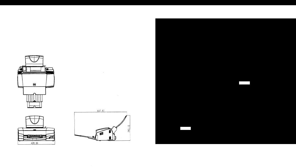
EPSON Stylus Photo 720 / EPSON Stylus Photo EX3
1.6 |
Physical Specification |
||
o |
Dimensions |
|
|
|
n |
Stylus Photo 720: |
429 x 268 x 168 mm (WxDxH) |
|
n |
Stylus Photo EX3: |
546 x 275 x 172 mm (WxDxH) |
Figure 1-11. Stylus Photo 720 Dimensions
Revision A
760.73
|
|
406 |
307.66 |
|
|
|
|
|
|
|
|
545.53
Figure 1-12. Stylus Photo EX3 Dimensions
o |
Weight |
|
|
|
n |
Stylus Photo 720: |
approximately 5.2kg |
|
n |
Stylus Photo EX3: |
approximately 7.0kg |
Product Description |
Physical Specification |
27 |

EPSON Stylus Photo 720 / EPSON Stylus Photo EX3 Revision A
1.7 Consumables and Options
The consumables for this printer are following;
Table 1-18. Consumables
Classification |
|
No. |
|
Name |
|
|
|
|
|
Consumables |
|
S020187 |
|
Ink Cartridge (black) |
|
|
|
|
|
|
S020193 |
|
Ink Cartridge (color) |
|
|
|
|
||
|
|
|
|
|
Product Description |
Consumables and Options |
28 |

C H A P T E R
2
OPERATING PRINCIPLES

EPSON Stylus Photo 720 / EPSON Stylus Photo EX3 |
Revision A |
2.1 Overview
This section describes the operating principles of the printer mechanism and electrical circuit boards. The Stylus Photo 720 / Stylus Photo EX3 has the following boards:
o |
Main board: |
C301MAIN |
o |
Power supply board: |
C301PSB/PSE |
o |
Panel board: |
C209PNL Board (Stylus Photo 720) |
|
|
C366PNL Board (Stylus Photo EX3) |
2.1.1 Printer Mechanism
Stylus Photo 720 / Stylus Photo EX3 is based on Stylus Photo 700 / Stylus Photo EX and the basic specifications for its mechanism are almost same as Stylus Photo 700 / Stylus Photo EX.
This printer consists of Print Head, Carriage Mechanism, Paper Feeding Mechanism, Paper Loading Mechanism, Ink System (Pump Mechanism, Cap Mechanism, and Carriage Lock Mechanism).
Like other EPSON ink jet printers, the Stylus Photo 720 / Stylus Photo EX3 is equipped with two stepping motors; one for ASF/ paper feeding/ pump mechanism, and one for CR mechanism. ASF unit uses rear entry front eject system; this design is the same as Stylus Photo 750 / Stylus Photo 1200.
For cap assembly, Stylus Photo 720 / Stylus Photo EX3 uses valveless mechanism; new design for this model.
Figure 2-1 on page 31 shows the outline of the printer mechanism.
The table below shows the compatibility of the mechanical units among Stylus Photo 700, Stylus Photo 750 and Stylus Photo 720.
Table 2-1. Mechanical Unit Compatibility
|
|
Stylus Photo 700 / |
|
Stylus Photo 750 / |
|
Stylus Photo 720 / |
|
|
Stylus Photo EX |
|
Stylus Photo 1200 |
|
Stylus Photo EX3 |
|
|
|
|
|
|
|
Printhead |
|
E-Chips |
|
U-Chips |
|
E-Chips + |
|
|
|
|
|
|
|
CR motor |
|
7.8Ω |
|
7.8Ω |
|
7.8Ω |
(coil resistance) |
|
|
|
|||
|
|
|
|
|
|
|
|
|
|
|
|
|
|
PF moto |
|
7.8Ω |
|
8.8Ω |
|
8.8Ω |
(coil resistance) |
|
|
|
|||
|
|
|
|
|
|
|
|
|
|
|
|
|
|
ASF unit |
|
--- |
|
Quiet noise type |
|
Quiet noise type |
|
|
|
|
|
|
|
Paper feeding |
|
Bottom edge: 14mm |
|
Bottom edge: 3mm |
|
Bottom edge: 3mm |
mechanism |
|
|
enabled |
|
enabled |
|
|
|
|
|
|||
|
|
|
|
|
|
|
Pump unit |
|
Type A |
|
Type B |
|
Type A |
|
|
|
|
|
|
|
Capping unit |
|
Valve A |
|
Valve B |
|
Valveless |
|
|
|
|
|
|
|
Frame parts |
|
Stylus Photo 700 type |
|
Stylus Photo 750 type |
|
Stylus Photo 750 type |
|
|
|
|
|
|
|
Main board |
|
C233MAIN |
|
C259MAIN |
|
C301MAIN |
|
|
|
|
|
|
|
PSB/PSE board |
|
C206PSB |
|
C257PSB |
|
C301PSB/PSE |
|
|
|
|
|
|
|
Operating Principles |
Overview |
30 |

EPSON Stylus Photo 720 / EPSON Stylus Photo EX3 |
Revision A |
Paper Loading |
Mechanism |
CR Unit
CR Mechanism (Printhead)
CR Motor
Paper Feed |
Capping Position |
Trigger Lever |
|
Position |
|
PF Motor |
|
Ink System |
|
|
|
|
|
|
Paper Feeding |
Cap |
|
Mechanism |
||
Mechanism |
||
|
CR Lock Mechanism
Pump
Mechanism
Figure 2-1. Printer Mechanism Block Diagram
Operating Principles |
Overview |
31 |
Loading...