


SERVICE MANUAL
Serial Impact Dot Matrix Printer
EPSON FX-890/2190
®
SEDM02003
Notice
All rights reserved. No part of this manual may be reproduced, stored in a retrieval system, or transmitted in any form or by any means electronic, mechanical, photocopying, or otherwise, without the prior written permission of SEIKO EPSON CORPORATION.
All effort have been made to ensure the accuracy of the contents of this manual. However, should any errors be detected, SEIKO EPSON would greatly appreciate being informed of them.
The contents of this manual are subject to change without notice.
The above not withstanding SEIKO EPSON CORPORATION can assume no responsibility for any errors in this manual or the consequences thereof.
EPSON is a registered trademark of SEIKO EPSON CORPORATION.
General Notice: |
Other product names used herein are for identification purpose only and may be trademarks or registered trademarks of their |
|
respective owners. EPSON disclaims any and all rights in those marks. |
Copyright © 2003 SEIKO EPSON CORPORATION.
Imaging & Information Product Division
TPCS Quality Assurance Department
PRECAUTIONS
Precautionary notations throughout the text are categorized relative to 1)Personal injury and 2) damage to equipment.
DANGER Signals a precaution which, if ignored, could result in serious or fatal personal injury. Great caution should be exercised in performing procedures preceded by DANGER Headings.
WARNING Signals a precaution which, if ignored, could result in damage to equipment.
The precautionary measures itemized below should always be observed when performing repair/maintenance procedures.
DANGER
1.ALWAYS DISCONNECT THE PRODUCT FROM THE POWER SOURCE AND PERIPHERAL DEVICES PERFORMING ANY MAINTENANCE OR REPAIR PROCEDURES.
2.NO WORK SHOULD BE PERFORMED ON THE UNIT BY PERSONS UNFAMILIAR WITH BASIC SAFETY MEASURES AS DICTATED FOR ALL ELECTRONICS TECHNICIANS IN THEIR LINE OF WORK.
3.WHEN PERFORMING TESTING AS DICTATED WITHIN THIS MANUAL, DO NOT CONNECT THE UNIT TO A POWER SOURCE UNTIL INSTRUCTED TO DO SO. WHEN THE POWER SUPPLY CABLE MUST BE CONNECTED, USE EXTREME CAUTION IN WORKING ON POWER SUPPLY AND OTHER ELECTRONIC COMPONENTS.
4.When disassembling or assembling a product, be sure to wear gloves to avoid injuries from metal parts with sharp edges.
WARNING
1.REPAIRS ON EPSON PRODUCT SHOULD BE PERFORMED ONLY BY AN EPSON CERTIFIED REPAIR TECHNICIAN.
2.MAKE CERTAIN THAT THE SOURCE VOLTAGES IS THE SAME AS THE RATED VOLTAGE, LISTED ON THE SERIAL NUMBER/RATING PLATE. IF THE EPSON PRODUCT HAS A PRIMARY AC RATING DIFFERENT FROM AVAILABLE POWER SOURCE, DO NOT CONNECT IT TO THE POWER SOURCE.
3.ALWAYS VERIFY THAT THE EPSON PRODUCT HAS BEEN DISCONNECTED FROM THE POWER SOURCE BEFORE REMOVING OR REPLACING PRINTED CIRCUIT BOARDS AND/OR INDIVIDUAL CHIPS.
4.IN ORDER TO PROTECT SENSITIVE MICROPROCESSORS AND CIRCUITRY, USE STATIC DISCHARGE EQUIPMENT, SUCH AS ANTI-STATIC WRIST STRAPS, WHEN ACCESSING INTERNAL COMPONENTS.
5.DO NOT REPLACE IMPERFECTLY FUNCTIONING COMPONENTS WITH COMPONENTS WHICH ARE NOT MANUFACTURED BY EPSON. IF SECOND
SOURCE IF’S OR OTHER COMPONENTS WHICH HAVE NOT BEEN APPROVED ARE USED, THEY COULD CAUSE DAMAGE TO THE EPSON PRODUCT, OR COULD VOID THE WARRANTY OFFERED BY EPSON.

About This Manual
This manual describes basic functions, theory of electrical and mechanical operations, maintenance and repair procedures of the printer. The instructions and procedures included herein are intended for the experienced repair technicians, and attention should be given to the precautions on the preceding page.
Manual Configuration
This manual consists of six chapters and Appendix.
CHAPTER 1. PRODUCT DESCRIPTIONS
Provides a general overview and specifications of the product.
CHAPTER 2. OPERATING PRINCIPLES
Describes the theory of electrical and mechanical operations of the product.
CHAPTER 3. TROUBLESHOOTING
Describes the step-by-step procedures for the troubleshooting.
CHAPTER 4. DISASSEMBLY / ASSEMBLY
Describes the step-by-step procedures for disassembling and assembling the product.
CHAPTER 5. ADJUSTMENT
Provides Epson-approved methods for adjustment.
CHAPTER 6. MAINTENANCE
Provides preventive maintenance procedures and the lists of Epson-approved lubricants and adhesives required for servicing the product.
APPENDIX Provides the following additional information for reference:
•Connector pin assignments
•Electric circuit boards components layout
•Electrical circuit boards schematics
•Exploded diagram & Parts List
Symbols Used in this Manual
Various symbols are used throughout this manual either to provide additional information on a specific topic or to warn of possible danger present during a procedure or an action. Be aware of all symbols when they are used, and always read NOTE, CAUTION, or WARNING messages.
Indicates an operating or maintenance procedure, practice or condition that is necessary to keep the product’s quality.
CAUTION |
Indicates an operating or maintenance procedure, practice, |
|
or condition that, if not strictly observed, could result in |
||
|
||
|
damage to, or destruction of, equipment. |
|
CHECK |
May indicate an operating or maintenance procedure, |
|
practice or condition that is necessary to accomplish a task |
||
POINT |
||
|
efficiently. It may also provide additional information that is |
|
|
related to a specific subject, or comment on the results |
|
|
achieved through a previous action. |
|
WARNING |
Indicates an operating or maintenance procedure, practice |
|
|
or condition that, if not strictly observed, could result in injury |
|
|
or loss of life. |
|
|
Indicates that a particular task must be carried out |
|
|
according to a certain standard after disassembly and |
|
|
before re-assembly, otherwise the quality of the |
|
|
components in question may be adversely affected. |
Revision Status
Revision |
|
Date of Issue |
|
Description |
|
|
|
|
|
A |
|
June 20, 2003 |
|
Formal first release |
|
|
|
|
|
|
|
|
|
Revision up: |
|
|
|
|
Chapter-3: Error Correction ("3.2.12 Fatal Error" on page 63) |
B |
|
August 21, 2003 |
|
Chapter-4: Error Correction ("4.2.3 C524MAIN Board" on page 74) |
|
|
|
|
Appendix: The part list and the exploded diagram for the FX-2190 are added. |
|
|
|
|
("7.3 Exploded Diagrams" on page 114, "7.4 Parts List" on page 122) |
|
|
|
|
|
|
|
|
|
|
|
|
|
|
|

EPSON FX-890/2190 |
Revision B |
Table of Contents
Chapter 1 PRODUCT DESCRIPTIONS |
|
1.1 Features ................................................................................................................ |
9 |
1.2 Interface ............................................................................................................. |
23 |
1.2.1 Parallel interface (Forward channel) ........................................................... |
23 |
1.2.2 Parallel interface (Reverse channel)............................................................ |
25 |
1.2.3 USB Interface ............................................................................................. |
26 |
1.2.4 Optional Interface ....................................................................................... |
27 |
1.2.5 Type-B Interface communication specification .......................................... |
27 |
1.2.6 Interface selection ....................................................................................... |
28 |
1.2.7 IEEE1284.4 protocol................................................................................... |
29 |
1.3 Operation ........................................................................................................... |
30 |
1.3.1 Control panel............................................................................................... |
30 |
1.3.2 Switches ...................................................................................................... |
30 |
1.3.2.1 Operation in Normal Mode.................................................................. |
30 |
1.3.2.2 Operations at Power-on ....................................................................... |
31 |
1.3.2.3 Operation in Default Setting Mode...................................................... |
31 |
1.3.3 Indicators ( LEDs )...................................................................................... |
31 |
1.3.3.1 Indications in Normal Mode ................................................................ |
31 |
1.3.4 Buzzer ......................................................................................................... |
33 |
1.3.5 Default Setting ............................................................................................ |
33 |
1.3.5.1 Setting Method .................................................................................... |
33 |
1.3.5.2 Setting Items ........................................................................................ |
34 |
1.3.6 EEPROM Clear Function ........................................................................... |
35 |
1.3.7 Bi-D Adjustment......................................................................................... |
36 |
1.4 Dimensions and Weight..................................................................................... |
37 |
1.4.1 FX-880T+ Mode ......................................................................................... |
41 |
1.4.1.1 Setting of FX-880T+ mode.................................................................. |
41 |
1.4.1.2 Supported commands .......................................................................... |
41 |
1.4.1.3 Default setting items ............................................................................ |
42 |
1.4.1.4 Printer defaults..................................................................................... |
42 |
1.4.1.5 Action of the printer ............................................................................ |
42 |
Chapter 2 Operating Principles |
|
2.1 Overview............................................................................................................. |
44 |
2.1.1 Printer Mechanism ...................................................................................... |
45 |
2.1.1.1 Printhead.............................................................................................. |
45 |
2.1.1.2 Paper Feed Mechanism ........................................................................ |
45 |
2.1.1.3 Carriage Movement Mechanism.......................................................... |
45 |
2.1.1.4 Tractor Feed Mechanism ..................................................................... |
45 |
2.1.1.5 Platen Gap Adjustment Mechanism..................................................... |
45 |
2.1.1.6 Ribbon Feed Mechanism ..................................................................... |
46 |
2.1.1.7 Sensors................................................................................................. |
46 |
2.1.2 Circuit Operation......................................................................................... |
47 |
2.1.2.1 C524 MAIN Board .............................................................................. |
47 |
2.1.2.2 C524 PSB/PSE/PSH Power Supply Circuit......................................... |
50 |
Chapter 3 Troubleshooting |
|
3.1 Overview............................................................................................................. |
53 |
3.1.1 Specified Tools ........................................................................................... |
53 |
3.1.2 Procedure for Troubleshooting ................................................................... |
53 |
3.1.3 Preliminary Checks ..................................................................................... |
54 |
3.1.4 Error ............................................................................................................ |
54 |
3.2 Troubleshooting Based on Symptoms .............................................................. |
55 |
3.2.1 Printer fails to operate when power is turned on ......................................... |
55 |
3.2.2 No LED on Control Panel lights up even with power turned on ................. |
56 |
3.2.3 Abnormal operation of Carriage at power on.............................................. |
56 |
3.2.4 Abnormal paper feeding.............................................................................. |
57 |
3.2.5 Printing is faulty during self-test, but carriage operation is normal ............ |
58 |
3.2.6 Abnormal operation of Control Panel ......................................................... |
59 |
3.2.7 Abnormal on-line operation (normal self-printing, though)........................ |
59 |
3.2.8 Abnormal operation of ribbon..................................................................... |
60 |
3.2.9 Abnormal operation of Carriage Unit ......................................................... |
61 |
3.2.10 Faulty print................................................................................................ |
62 |
6

EPSON FX-890/2190 |
|
3.2.11 Electrical Noise......................................................................................... |
62 |
3.2.12 Fatal Error ................................................................................................. |
63 |
3.3 Troubleshooting for Individual Units .............................................................. |
64 |
3.3.1 Main Component Checking Point............................................................... |
64 |
Chapter 4 Disassembly and Assembly |
|
4.1 Overview............................................................................................................. |
66 |
4.1.1 Disassembly Precautions ............................................................................ |
66 |
4.1.2 Tools and Instruments................................................................................. |
66 |
4.1.3 Service Check After Repair ........................................................................ |
67 |
4.1.3.1 Abbreviations for Small Parts.............................................................. |
68 |
4.2 Main Components Disassembly........................................................................ |
69 |
4.2.1 Pre-disassembly Procedures........................................................................ |
70 |
4.2.2 Upper Housing ............................................................................................ |
72 |
4.2.3 C524MAIN Board ...................................................................................... |
74 |
4.2.4 C524PSB/PSE/PSH Board.......................................................................... |
76 |
4.3 Printer Mechanism Disassembly ...................................................................... |
77 |
4.3.1 Printhead ..................................................................................................... |
77 |
4.3.2 HP (Home Position) Detector ..................................................................... |
78 |
4.3.3 Platen .......................................................................................................... |
79 |
4.3.4 Printer Mechanism ...................................................................................... |
80 |
4.3.5 CR Motor .................................................................................................... |
81 |
4.3.6 PF Motor ..................................................................................................... |
83 |
4.3.7 PF Gear Train.............................................................................................. |
84 |
4.3.8 PG (Platen Gap) Detector ........................................................................... |
86 |
4.3.9 Release Detector ......................................................................................... |
86 |
4.3.10 Front PE (Paper End) Detector ................................................................. |
87 |
4.3.11 Rear PE Detector....................................................................................... |
87 |
4.3.12 Carriage Assembly.................................................................................... |
88 |
4.3.13 Rear Paper Guide Assembly ..................................................................... |
90 |
4.3.14 Ribbon Drive (RD) Assembly................................................................... |
92 |
Chapter 5 Adjustment |
|
5.1 Adjustment Overview........................................................................................ |
94 |
5.1.1 Required Adjustment .................................................................................. |
94 |
5.1.2 Adjustment Tools........................................................................................ |
94 |
5.2 Adjusting and Resetting the Printer ................................................................ |
95 |
|
|
Revision B |
|
5.2.1 Platen Gap Adjustment ............................................................................... |
95 |
5.3 |
Adjustment Program......................................................................................... |
97 |
|
5.3.1 Preparation .................................................................................................. |
97 |
|
5.3.1.1 System Requirement............................................................................ |
97 |
|
5.3.1.2 Installation ........................................................................................... |
97 |
|
5.3.1.3 Running the Program ........................................................................... |
97 |
Chapter 6 Maintenance |
|
|
6.1 |
Overview............................................................................................................. |
99 |
|
6.1.1 Preventive Maintenance .............................................................................. |
99 |
6.2 |
Lubrication....................................................................................................... |
100 |
Chapter 7 Appendix |
|
|
7.1 |
Connector Summary ....................................................................................... |
105 |
7.2 |
Electric Circuit Diagrams ............................................................................... |
108 |
7.3 |
Exploded Diagrams ......................................................................................... |
114 |
7.4 |
Parts List .......................................................................................................... |
122 |
7

1CHAPTER
PRODUCT DESCRIPTIONS
EPSON FX-890/2190
1.1 Features
EPSON FX-890/2190 is a small-foot 18-pin serial impact dot matrix printer.
HARDWARE SPECIFICATIONS
Print method |
: Impact Dot Matrix |
Number of pins |
: 18 pins |
Print pin arrangement |
: 9 pins x 2 files |
Print pin diameter |
: 0.29 mm (0.0114 inch) |
Color |
: Black ink ribbon |
Print Direction |
: Bi-direction with logic seeking |
RESOLUTION
Table 1-1. Resolution ( dpi )
Printing Mode |
Horizontal Density |
Vertical |
Adjacent Dot |
|
Density |
||||
|
|
|||
|
|
|
|
Ultra Speed Draft |
80 dpi |
72 dpi |
No |
|
10 cpi |
||||
|
|
|
||
|
|
|
|
|
Ultra Speed Draft |
84 dpi |
72 dpi |
No |
|
12 cpi |
||||
|
|
|
||
|
|
|
|
|
High Speed Draft |
90 dpi |
72 dpi |
No |
|
10 cpi |
||||
|
|
|
||
|
|
|
|
|
High Speed Draft |
96 dpi |
72 dpi |
No |
|
12 cpi |
||||
|
|
|
||
|
|
|
|
|
Draft |
120 dpi |
72 dpi |
No |
|
|
|
|
|
|
Draft Condensed |
240 dpi |
72 dpi |
No |
|
|
|
|
|
|
Draft Emphasized |
120 dpi |
72 dpi |
Yes |
|
|
|
|
|
|
NLQ |
240 dpi |
144 dpi |
No |
|
|
|
|
|
|
Bit Image |
60, 72, 80, 90 or 120 dpi |
72 dpi |
Yes |
|
|
|
|
||
120 or 240 dpi |
72 dpi |
No |
||
|
||||
|
|
|
|
Manualsbooks.Com
Revision B
PRINTING SPEED
Table 1-2. Printing Speed (cps) and Printable Columns
Printing Mode |
Character |
Printable Columns |
Printing Speed |
|||
Pitch |
|
|
|
|
||
FX-890 |
FX-2190 |
Normal |
Copy |
|||
|
||||||
|
10 cpi |
80 |
136 |
566 |
489 |
|
Ultra Speed Draft |
|
|
|
|
12 cpi |
96 |
163 |
680 |
571 |
10 cpi |
80 |
136 |
559 |
476 |
High Speed Draft |
12 cpi |
96 |
163 |
627 |
539 |
|
|
|
|
|
|
|
15 cpi |
120 |
204 |
629 |
520 |
High Speed Draft |
17 cpi |
137 |
233 |
595 |
463 |
|
|
|
|
|
|
Condensed |
20 cpi |
160 |
272 |
541 |
419 |
|
|||||
|
10 cpi |
80 |
136 |
419 |
347 |
Draft |
12 cpi |
96 |
163 |
503 |
416 |
|
15 cpi |
120 |
204 |
405 |
314 |
Draft Condensed |
17 cpi |
137 |
233 |
359 |
300 |
|
|
|
|
|
|
|
20 cpi |
160 |
272 |
419 |
350 |
|
|
|
|
|
|
|
|
|
|
Draft Emphasized |
10 cpi |
80 |
136 |
209 |
173 |
|
|
|
|
|
|
|
|
|
|
|
10 cpi |
80 |
136 |
104.6 |
87.5 |
|
|
|
|
|
|
|
|
|
|
|
12 cpi |
96 |
163 |
125.9 |
105.0 |
|
|
|
NLQ |
15 cpi |
120 |
204 |
100.8 |
78.5 |
|
17 cpi |
137 |
233 |
89.7 |
38.5 |
20 cpi |
160 |
272 |
104.6 |
44.9 |
Note1: When the power supply voltage drops to the lower limit, the printer stops printing and then starts printing remains on that line again more slowly than before.
2:When the head temperature rises to the upper limit, the printer stops printing. When the head temperature falls to the normal level, the printer starts printing again more slowly than before.

EPSON FX-890/2190 |
|
|
|
|
|
FEEDING METHOD |
|
|
|
|
|
Friction feed |
: Front, Rear |
|
Push tractor feed |
: Front, Rear |
|
Push & Pull tractor feed : Front, Rear |
|
|
Pull tractor feed |
: Front, Rear, Bottom |
|
|
|
|
FEED SPEED |
|
|
|
|
|
Normal mode |
4.23 mm (1/6 inch feed) |
62 msec |
|
Continuous feed |
0.127 MPS (m/sec) |
|
|
[5.0 IPS (inches/sec)] |
Copy mode |
4.23 mm (1/6 inch feed) |
83 msec |
|
Continuous feed |
0.078 MPS (m/sec) |
|
|
[3.1 IPS (inches/sec)] |
FEEDER
Front push tractor
Rear push tractor
CSF Bin 1 / Bin 2 (Option)
Pull tractor ( Option )
Roll paper holder (Option)
|
|
|
|
Revision B |
|
PAPER SPECIFICATIONS |
|
|
|
||
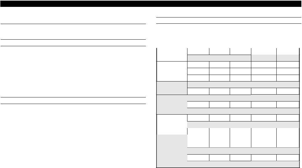
Table 1-3. Cut Sheet (Single sheet, Not multi part) FX-890 |
|||||
|
Front Entry |
|
Rear Entry |
|
|
FX-890 |
Manual |
Manual |
High-Capacity |
Single-Bin CSF |
|
CSF |
|||||
|
|
|
|
||
|
|
Min. |
|
|
Max. |
|
Min. |
|
|
Max. |
|
Min. |
|
Max. |
|
Min. |
|
Max. |
|
|
|
|
|
|
|
|
|
|
|
|
|
|
|
|
|
|
|
Width |
(inch) |
(3.9) |
|
|
(10.1) |
|
(3.9) |
|
|
(10.1) |
|
(3.9) |
|
(8.5) |
|
(7.2) |
|
(8.5) |
|
(mm) |
100 |
|
|
257 |
|
100 |
|
|
257 |
|
100 |
|
216 |
|
182 |
|
216 |
|
|
|
|
|
|
|
|
|
|
|
|
|
|
|
|
|
|
|
Length |
(inch) |
(3.9) |
|
|
(14.3) |
|
(3.9) |
|
|
(14.3) |
|
(3.9) |
|
(14.3) |
|
(8.3) |
|
(14.3) |
|
(mm) |
100 |
|
|
364 |
|
100 |
|
|
364 |
|
100 |
|
364 |
|
210 |
|
364 |
|
|
|
|
|
|
|
|
|
|
|
|
|
|
|
|
|
|
|
Thickness |
(inch) |
(0.0025) |
|
|
(0.0055) |
|
(0.0025) |
|
|
(0.0055) |
|
(0.0028) |
|
(0.0055) |
|
(0.0028) |
|
(0.0055) |
|
(mm) |
0.065 |
|
|
0.14 |
|
0.065 |
|
|
0.14 |
|
0.07 |
|
0.14 |
|
0.07 |
|
0.14 |
|
|
|
|
|
|
|
|
|
|
|
|
|
|
|
|
|
|
|
Weight |
(g/m2) |
52 |
|
|
90 |
|
52 |
|
|
90 |
|
64 |
|
90 |
|
64 |
|
90 |
|
(lb) |
(14) |
|
|
(24) |
|
(14) |
|
|
(24) |
|
(18) |
|
(24) |
|
(18) |
|
(24) |
|
|
|
|
|
|
|
|
|
|
|
|
|
|
|
|
|
|
|
CSF Capacity |
--- |
|
|
--- |
|
|
185 sheets with the |
|
60 sheets with the form |
|||||||||
|
|
|
|
|
|
|
|
|
|
|
|
form 64 g/m2 (17lb) *1 |
|
64 g/m2 (17lb) *2 |
||||
|
|
|
|
|
|
|
|
|
|
|
|
150 sheets with the |
|
50 sheets with the form |
||||
|
|
|
|
|
|
|
|
|
|
|
|
form 82 g/m2 (22lb) *1 |
|
82 g/m2 (22lb) *2 |
||||
Quality |
|
Plain paper, Reclaimed paper |
|
|
|
|
|
|
|
|
|
|||||||
|
|
Not curled, not folded, not crumpled |
|
|
|
|
|
|
|
|
||||||||
|
|
|
|
|
|
|
|
|
|
|
|
|
|
|
|
|
|
|
Note : Printing on reclaimed paper is available only under normal temperature and humidity conditions.
Note “*1”: When using High-Capacity CSF, paper total thickness is below 15 mm. “*2” : When using Single-Bin CSF, paper total thickness is below 5 mm.
Manualsbooks.Com
EPSON FX-890/2190 |
Revision B |
Table 1-4. Cut Sheet (Single sheet, Not multi part) FX-2190
|
|
|
Front Entry |
|
|
|
|
|
|
Rear Entry |
|
|
|
|
|||||
FX-2190 |
|
Manual |
|
Manual |
|
High-Capacity |
|
Single-Bin CSF |
|||||||||||
|
|
|
CSF |
|
|||||||||||||||
|
|
|
|
|
|
|
|
|
|
|
|
|
|
|
|
|
|||
|
|
|
Min. |
|
|
Max. |
|
Min. |
|
|
Max. |
|
Min. |
|
Max. |
|
Min. |
|
Max. |
|
|
|
|
|
|
|
|
|
|
|
|
|
|
|
|
|
|
|
|
Width |
(inch) |
|
(3.9) |
|
|
(16.5) |
|
(3.9) |
|
|
(16.5) |
|
(3.9) |
|
(16.5) |
|
(7.2) |
|
(16.5) |
|
(mm) |
|
100 |
|
|
420 |
|
100 |
|
|
420 |
|
100 |
|
420 |
|
182 |
|
420 |
|
|
|
|
|
|
|
|
|
|
|
|
|
|
|
|
|
|
|
|
Length |
(inch) |
|
(3.9) |
|
|
(16.5) |
|
(3.9) |
|
|
(16.5) |
|
(3.9) |
|
(16.5) |
|
(8.3) |
|
(14.3) |
|
(mm) |
|
100 |
|
|
420 |
|
100 |
|
|
420 |
|
100 |
|
420 |
|
210 |
|
364 |
Thickness |
(inch) |
|
(0.0025) |
|
|
(0.0055) |
|
(0.0025) |
|
|
(0.0055) |
|
(0.0028) |
|
(0.0055) |
|
(0.0028) |
|
(0.0055) |
|
(mm) |
|
0.065 |
|
|
0.14 |
|
0.065 |
|
|
0.14 |
|
0.07 |
|
0.14 |
|
0.07 |
|
0.14 |
|
|
|
|
|
|
|
|
|
|
|
|
|
|
|
|
|
|
|
|
Weight |
(g/m2) |
|
52 |
|
|
90 |
|
52 |
|
|
90 |
|
64 |
|
90 |
|
64 |
|
90 |
|
(lb) |
|
(14) |
|
|
(24) |
|
(14) |
|
|
(24) |
|
(18) |
|
(24) |
|
(18) |
|
(24) |
CSF Capacity |
|
--- |
|
|
--- |
|
|
185 sheets with the |
|
60 sheets with the form |
|||||||||
|
|
|
|
|
|
|
|
|
|
|
|
|
form 64 g/m2 (17lb) *1 |
|
64 g/m2 (17lb) *2 |
||||
|
|
|
|
|
|
|
|
|
|
|
|
|
150 sheets with the |
|
50 sheets with the form |
||||
|
|
|
|
|
|
|
|
|
|
|
|
|
form 82 g/m2 (22lb) *1 |
|
82 g/m2 (22lb) *2 |
||||
Quality |
|
|
Plain paper, Reclaimed paper |
|
|
|
|
|
|
|
|
|
|||||||
|
|
|
Not curled, not folded, not crumpled |
|
|
|
|
|
|
|
|
||||||||
|
|
|
|
|
|
|
|
|
|
|
|
|
|
|
|
|
|
|
|
Note : Printing on reclaimed paper is available only under normal temperature and humidity conditions
Note “*1”: When using High-Capacity CSF, paper total thickness is below 15 mm. “*2” : When using Single-Bin CSF, paper total thickness is below 5 mm.
Table 1-5. Cut Sheet (Multi part) FX-890
|
|
|
Front Entry |
|
Rear Entry |
|||||
|
|
|
|
|
|
|
|
|
|
|
FX-890 |
|
|
Manual |
|
Manual / High-Capacity |
|||||
|
|
|
CSF / Single-Bin CSF |
|||||||
|
|
|
|
|
|
|
||||
|
|
|
Minimum |
|
Maximum |
|
Minimum |
|
|
Maximum |
|
|
|
|
|
|
|
|
|
|
|
Width |
(inch) |
|
(3.9) |
|
(10.1) |
|
----- |
|
|
----- |
|
(mm) |
|
100 |
|
257 |
|
|
|
|
|
|
|
|
|
|
|
|
|
|
|
|
Length |
(inch) |
|
(3.9) |
|
(14.3) |
|
----- |
|
|
----- |
|
|
|
|
|
|
|
|
|
|
|
|
(mm) |
|
100 |
|
364 |
|
|
|
|
|
|
|
|
|
|
|
|
|
|
|
|
Copies |
|
|
1 original + 5 copies |
|
|
----- |
||||
|
|
|
|
|
|
|
|
|||
Total thickness |
(inch) |
|
(0.0047) |
|
(0.018) |
|
----- |
|
|
----- |
|
(mm) |
|
0.12 |
|
0.46 |
|
|
|
|
|
|
|
|
|
|
|
|
|
|
|
|
Weight |
(g/m2) |
|
40 |
|
58 |
|
----- |
|
|
----- |
(one sheet of multi part) |
(lb) |
|
(12) |
|
(15) |
|
|
|
|
|
|
|
|
|
|
|
|
|
|
|
|
|
|
|
|
|
|
|
|
|
|
|
Quality |
|
|
Plain paper, Reclaimed paper |
|
|
----- |
||||
|
|
|
Not curled, not folded, |
|
|
|
|
|
||
|
|
|
not crumpled |
|
|
|
|
|
|
|
|
|
|
|
|
|
|
|
|
|
|
Jointing |
|
|
Line glue at the top side of form |
|
----- |
|
|
----- |
||
|
|
|
|
|
|
|
|
|
|
|
Note1: Type of paper of multi-part forms should be Carbonless. Don’t use Carbon-backed and Carbon-interleaved.
2: Type of paper of line glue at the top should be set jointing side of paper horizontally.
Manualsbooks.Com

EPSON FX-890/2190
Table 1-6. Cut Sheet (Multi part) FX-2190
|
|
|
Front Entry |
|
Rear Entry |
|||||
|
|
|
|
|
|
|
|
|
|
|
FX-2190 |
|
|
Manual |
|
Manual / High-Capacity CSF |
|||||
|
|
|
/ Single-Bin CSF |
|||||||
|
|
|
|
|
|
|
||||
|
|
|
Minimum |
|
Maximum |
|
Minimum |
|
|
Maximum |
|
|
|
|
|
|
|
|
|
|
|
Width |
(inch) |
|
(3.9) |
|
(16.5) |
|
----- |
|
|
----- |
|
(mm) |
|
100 |
|
420 |
|
|
|
|
|
|
|
|
|
|
|
|
|
|
|
|
Length |
(inch) |
|
(3.9) |
|
(16.5) |
|
----- |
|
----- |
|
|
(mm) |
|
100 |
|
420 |
|
|
|
|
|
|
|
|
|
|
|
|
|
|
|
|
Copies |
|
|
1 original + 5 copies |
|
|
----- |
||||
|
|
|
|
|
|
|
|
|
|
|
Total thickness |
(inch) |
|
(0.0047) |
|
(0.018) |
|
----- |
|
|
----- |
|
(mm) |
|
0.12 |
|
0.46 |
|
|
|
|
|
|
|
|
|
|
|
|
|
|
|
|
Weight |
(g/m2) |
|
40 |
|
58 |
|
----- |
|
|
----- |
(one sheet of multi part) |
(lb) |
|
(12) |
|
(15) |
|
|
|
|
|
|
|
|
|
|
|
|
|
|
|
|
|
|
|
|
|
|
|
|
|
|
|
Quality |
|
|
Plain paper, Reclaimed paper |
|
|
----- |
||||
|
|
|
Not curled, not folded, |
|
|
|
|
|
||
|
|
|
not crumpled |
|
|
|
|
|
|
|
|
|
|
|
|
|
|
||||
Jointing |
|
|
Line glue at the top side of |
|
----- |
|
|
----- |
||
|
|
|
form |
|
|
|
|
|
|
|
|
|
|
|
|
|
|
|
|
|
|
Note 1: Type of paper of multi-part forms should be Crbonless. Don’t use Carbon-backed and Carbon-interleaved.
2: Type of paper of line glue at the top should be set jointing side of paper horizontally.
|
|
|
|
|
|
|
|
|
|
|
|
|
|
|
|
|
Revision B |
|||
|
|
|
|
|
Table 1-7. Card |
|
|
|
|
|
|
|
|
|||||||
|
|
|
|
|
|
|
|
|
|
|
|
|
|
|
|
|
|
|
|
|
FX-890 |
|
|
Front Entry |
|
|
|
|
|
|
|
Rear Entry |
|
|
|
|
|||||
|
|
|
|
|
|
|
|
|
|
|
|
High-Capacity |
|
Single-Bin |
||||||
& |
|
|
Manual |
|
Manual |
|
|
|
||||||||||||
|
|
|
|
|
|
CSF |
|
CSF |
||||||||||||
FX-2190 |
|
|
|
|
|
|
|
|
|
|
|
|
|
|
||||||
|
|
Min. |
|
Max. |
|
Min. |
|
|
Max. |
|
|
Min. |
|
|
Max. |
|
Min. |
|
Max. |
|
|
|
|
|
|
|
|
|
|
|
|
|
|
||||||||
Width |
(inch) |
|
(3.9) |
|
(5.8) |
|
(3.9) |
|
|
(5.8) |
|
|
(3.9) |
|
|
(5.8) |
|
--- |
|
--- |
|
(mm) |
|
100 |
|
148 |
|
100 |
|
|
148 |
|
|
100 |
|
|
148 |
|
|
|
|
|
|
|
|
|
|
|
|
|
|
|
|
|
|
|
|
|
|
|
|
|
Length |
(inch) |
|
(5.8) |
|
(3.9) |
|
|
(5.8) |
|
|
(3.9) |
|
|
(5.8) |
|
--- |
|
--- |
||
|
(mm) |
|
148 |
|
100 |
|
|
148 |
|
|
100 |
|
|
148 |
|
|
|
|
||
|
|
|
|
|
|
|
|
|
|
|
|
|
|
|
|
|
|
|
|
|
Thickness |
(inch) |
|
(0.0087) |
|
(0.0087) |
|
|
(0.0087) |
|
--- |
|
--- |
||||||||
|
(mm) |
|
0.22 |
|
|
0.22 |
|
|
|
0.22 |
|
|
|
|
||||||
|
|
|
|
|
|
|
|
|
|
|
|
|
|
|
||||||
Weight |
(g/m2) |
|
192 |
|
|
192 |
|
|
|
192 |
|
--- |
|
--- |
||||||
|
(lb) |
|
(51) |
|
|
(51) |
|
|
|
(51) |
|
|
|
|
||||||
|
|
|
|
|
|
|
|
|
|
|
|
|
|
|
|
|
|
|
|
|
Quality |
|
|
Plain paper, Reclaimed paper |
|
|
|
|
|
|
|
|
|||||||||
|
|
|
Not curled, not folded, not crumpled |
|
|
|
|
|
|
|
|
|||||||||
|
|
|
|
|
|
|
|
|
|
|
|
|
|
|
|
|
|
|
|
|
Note1: Printing on card is available only under normal temperature and humidity conditions
2:When setting cards, be sure to align their left edge with the matchmark of the sheet guide.
3:When Paper size is A6 and the sheet is to be set horizontal, it should be inserted from rear entrance only.
4:When using card, set up card mode.
Manualsbooks.Com

EPSON FX-890/2190 |
|
|
|
|
|
|
|
|
|
|
|
|
|
|
|
|
|
|
|
|
|
|
|
|
|
|
|
|
|
|
|
|
Revision B |
|||||||
|
|
|
|
Table 1-8. Envelope |
|
|
|
|
|
|
Table 1-9. Handling possible cut sheets of fixed forms |
|
|
|
||||||||||||||||||||||||||
|
|
|
|
|
|
|
|
|
|
|
|
|
|
|
|
|
(single sheet/multi-part) with FX-890 |
|
|
|
|
|
|
|
||||||||||||||||
FX-890 |
|
Front Entry |
|
|
|
|
|
Rear Entry |
|
|
|
|
|
|
|
|
|
|
|
|||||||||||||||||||||
|
|
|
|
|
|
|
|
High-Capacity |
Single-Bin |
|
|
|
|
|
|
|
|
|
|
|
|
|
|
|
|
|
|
|
|
|
|
|
|
|
|
|||||
|
& |
|
Manual |
Manual |
|
|
|
|
|
Size |
|
|
|
|
|
|
|
|
|
|
|
|
|
|
|
|
|
|
|
|
|
|
||||||||
|
|
|
|
CSF |
CSF |
|
|
|
|
A3 |
|
B4 |
|
A4 |
|
B5 |
|
|
A5 |
|
A6 |
|
Envelope |
|||||||||||||||||
|
|
|
|
|
|
|
|
|
|
|
|
|
|
|
|
|||||||||||||||||||||||||
FX-2190 |
|
|
|
|
|
|
|
|
|
Direction |
|
|
|
|
|
|
|
|
|
|
||||||||||||||||||||
|
Min. |
Max. |
Min. |
|
Max. |
|
|
Min. |
|
Max. |
Min. |
Max. |
|
|
|
|
|
|
|
|
|
|
|
|
|
|
|
|
|
|
|
|
|
|
|
|
|
|||
|
|
|
|
|
|
|
|
|
|
|
|
|
|
|
|
|
|
|
|
|
|
|
|
|
|
|
|
|
|
|
|
|
||||||||
Envelope |
Width |
(inch) |
----- |
|
(6.5) |
|
|
----- |
|
Rear Entry |
Vertical |
|
|
------/ |
|
---/ |
|
|
---/ |
|
|
---/ |
|
|
|
---/ |
|
|
---/ |
|
|
--- |
||||||||
(No.6) |
|
(mm) |
|
|
|
165 |
|
|
|
|
|
(manual) |
Horizontal |
|
|
---/--- |
---/--- |
|
|
---/--- |
|
|
/--- |
|
|
|
/--- |
|
|
/--- |
|
|
|
|||||||
|
|
|
|
|
|
|
|
|
|
|
|
|
|
|
|
|
|
|
|
|
|
|
|
|
|
|
|
|
|
|
|
|
|
|
|
|
|
|
|
|
|
Length |
(inch) |
----- |
|
(3.6) |
|
|
----- |
|
|
|
|
|
|
|
|
|
|
|
|
|
|
|
|
|
|
|
|
|
|
|
|
|
|||||||
|
|
(mm) |
|
|
|
92 |
|
|
|
|
|
|
Front Entry |
Vertical |
|
|
---/--- |
/ |
|
|
|
/ |
|
|
|
/ |
|
|
|
/ |
|
|
/ |
|
|
--- |
||||
|
|
|
|
|
|
|
|
|
|
|
|
|
|
|
|
|
|
|
|
|
|
|
|
|
|
|
|
|
|
|
|
|
|
|
|
|||||
|
|
|
|
|
|
|
|
|
|
|
|
|
|
|
|
(manual) |
Horizontal |
|
|
------/ |
------/ |
|
|
------/ |
|
|
/ |
|
/ |
|
/ |
|
--- |
|||||||
Envelope |
Width |
(inch) |
----- |
|
(9.5) |
|
|
----- |
|
|
||||||||||||||||||||||||||||||
|
|
|
|
|
|
|
|
|
|
|
|
|
|
|
|
|
|
|
|
|
|
|
|
|
|
|
|
|
||||||||||||
|
|
|
|
|
Vertical |
|
|
---/ |
---/ |
|
|
/ |
|
|
/ |
|
|
|
/ |
|
|
/ |
|
|
--- |
|||||||||||||||
(No.10) |
|
(mm) |
|
|
|
241 |
|
|
|
|
|
High-Capacity CSF |
|
|
|
|
|
|
|
|
|
|
|
|
|
|||||||||||||||
|
Length |
(inch) |
----- |
|
(4.1) |
|
|
----- |
|
|
Horizontal |
|
|
------/ |
------/ |
|
|
------/ |
|
|
---/ |
|
|
|
---/ |
|
|
---/ |
|
|
|
|||||||||
|
|
(mm) |
|
|
|
105 |
|
|
|
|
|
|
Vertical |
|
|
---/--- |
---/--- |
|
|
|
/--- |
|
|
|
/--- |
|
|
|
--- |
|
--- |
|
--- |
|||||||
Total Thickness |
(inch) |
----- |
(0.0063) |
|
(0.0205) |
|
|
(0.0063) |
|
(0.0205) |
----- |
|
Single-Bin CSF |
|
|
|
|
|
|
|
|
|
|
|
|
|
|
|
|
|
|
|
|
|
|
|
|
|||
|
|
|
|
|
|
Horizontal |
|
|
---/ |
---/ |
|
|
---/ |
|
|
---/ |
|
|
|
--- |
|
--- |
|
--- |
||||||||||||||||
|
|
(mm) |
|
|
0.16 |
|
0.52 |
|
|
0.16 |
|
0.52 |
|
|
|
|
|
|
|
|
|
|
|
|
|
|
|
|||||||||||||
|
|
|
|
|
|
|
|
|
|
|
|
|
|
|
|
|
|
|
|
|
|
|
|
|
|
|
|
|
|
|
|
|
|
|
|
|||||
|
|
|
|
|
|
|
|
|
|
|
|
|
|
|
|
|
|
|
|
|
|
|
|
|
|
|
|
|
|
|
|
|
|
|
|
|
|
|
|
|
|
|
----- |
The difference of thickness at the printable |
----- |
|
|
|
|
|
|
|
|
|
|||
|
|
|
area is within 0.25 mm (0.0098 inch) |
|
|
Table 1-10. Handling possible cut sheets of fixed forms |
|
|||||||||
Weight |
(g/m2) |
----- |
45 |
90 |
45 |
90 |
----- |
|
(single sheet/multi-part) with FX-2190 |
|
|
|
||||
|
(lb) |
|
(12) |
(24) |
(12) |
(24) |
|
|
|
Size |
|
|
|
|
|
|
CSF capacity |
|
|
|
|
25 sheets (24lb) |
---- |
Direction |
|
A3 |
B4 |
A4 |
B5 |
A5 |
A6 |
Envelope |
|
|
|
|
|
|
|
|
|
|
|
|
|
|||||
|
|
|
|
|
30 sheets (12lb) |
---- |
Rear Entry |
Vertical |
/--- |
/--- |
/--- |
/--- |
/--- |
/--- |
--- |
|
Quality |
|
|
BOND paper, PLAIN paper or AIR |
----- |
|
(manual) |
|
Horizontal |
/--- |
/--- |
/--- |
/--- |
/--- |
/--- |
|
|
|
----- |
|
|
Front Entry |
|
Vertical |
/ |
/ |
/ |
/ |
/ / |
--- |
|
|||
|
No glue at a flap |
|
|
|
||||||||||||
|
|
|
|
|
(manual) |
Horizontal |
/ |
/ |
/ |
/ |
/ |
/ |
--- |
|
||
|
|
|
Not curled, not folded, not crumpled |
|
|
|
||||||||||
|
|
|
|
|
|
|
|
|
|
|
|
|
|
|
|
|
|
|
|
|
|
|
|
|
Vertical |
TBD |
TBD |
TBD |
TBD |
TBD |
TBD |
TBD |
|
Note 1: Printing on envelope is available only under normal temperature and humidity |
|
|
High-Capacity CSF |
|
|
|||||||||||
|
|
|
|
|
|
|
|
|
|
|
|
|||||
|
|
|
Horizontal |
TBD |
TBD |
TBD |
TBD |
TBD |
TBD |
TBD |
|
|||||
conditions |
|
|
|
|
|
|
||||||||||
|
|
|
|
|
|
|
|
|
|
|
|
|
|
|
|
|
2: Set the longer side of envelope horizontally. |
|
|
Single-Bin CSF |
|
Vertical |
TBD |
TBD |
TBD |
TBD |
TBD |
TBD |
TBD |
|
|||
3: When setting envelopes of No. 6 paper size, be sure to align their left edge with the |
|
|
|
|
|
|
|
|
|
|
|
|||||
|
|
Horizontal |
TBD |
TBD |
TBD |
TBD |
TBD |
TBD |
TBD |
|
||||||
|
|
|
|
|||||||||||||
matchmark of the sheet guide. |
|
|
|
|
|
|
|
|
|
|
|
|
|
|
||
|
|
|
|
|
|
|
|
|
|
|
|
|
|
|||
4:Envelope should be inserted from rear entrance only.
5:Except for AIRMAIL, the sheets stacked must not exceed 4 sheets.
6:Printing is allowed only on the front side; printing on the back side is impossible.
Manualsbooks.Com

EPSON FX-890/2190
Table 1-11. Continuous paper (Single sheet and Multi Part) FX-890
FX-890 |
|
|
Bottom/Front/Rear Entry |
|||
|
|
Minimum |
|
|
Maximum |
|
|
|
|
|
|
||
|
|
|
|
|
|
|
Width |
(inch) |
|
(4) |
|
|
(10) |
|
(mm) |
|
101.6 |
|
|
254 |
|
|
|
|
|
|
|
Length (one page) |
(inch) |
|
(4) |
|
|
(22) |
|
(mm) |
|
101.6 |
|
|
558.8 |
|
|
|
|
|
|
|
Copies |
|
|
1 original + 5 copies * |
|||
|
|
|
|
|
|
|
Total thickness |
(inch) |
|
(0.0025) |
|
|
(0.018) |
|
(mm) |
|
0.065 |
|
|
0.46 |
|
|
|
|
|
|
|
Weight |
(g/m2) |
|
52 |
|
|
82 |
(not multi part) |
(lb) |
|
(14) |
|
|
(22) |
|
|
|
|
|
|
|
Weight |
(g/m2) |
|
40 |
|
|
58 |
(one sheet of multi part) |
(lb) |
|
(12) |
|
|
(15) |
|
|
|
|
|
|
|
Quality |
|
|
Plain paper, Reclaimed paper |
|||
|
|
|
Carbonless multi part paper |
|
||
|
|
|
Not break, without wrinkle, without tear, |
|||
|
|
|
without turn over |
|
||
|
|
|
|
|||
Jointing |
|
|
Point glue or paper staple(both side) |
|||
|
|
|
|
|
|
|
Note “*” : When pull tractor is used, 1 original + 6 copies are available only under normal temperature and humidity conditions.
Revision B
Table 1-12. Continuous paper (Single sheet and Multi Part) FX-1190
FX-2190 |
|
|
Bottom/Front/Rear Entry |
|||
|
|
Minimum |
|
|
Maximum |
|
|
|
|
|
|
||
|
|
|
|
|
|
|
Width |
(inch) |
|
(4) |
|
|
(16) |
|
(mm) |
|
101.6 |
|
|
406.4 |
|
|
|
|
|
|
|
Length (one page) |
(inch) |
|
(4) |
|
|
(22) |
|
(mm) |
|
101.6 |
|
|
558.8 |
|
|
|
|
|
|
|
Copies |
|
|
1 original + 5 copies * |
|||
|
|
|
|
|
|
|
Total thickness |
(inch) |
|
(0.0025) |
|
|
(0.018) |
|
(mm) |
|
0.065 |
|
|
0.46 |
|
|
|
|
|
|
|
Weight |
(g/m2) |
|
52 |
|
|
82 |
(not multi part) |
(lb) |
|
(14) |
|
|
(22) |
|
|
|
|
|
|
|
Weight |
(g/m2) |
|
40 |
|
|
58 |
(one sheet of multi part) |
(lb) |
|
(12) |
|
|
(15) |
|
|
|
|
|
|
|
Quality |
|
|
Plain paper, Reclaimed paper |
|||
|
|
|
Carbonless multi part paper |
|
||
|
|
|
Not break, without wrinkle, without tear, |
|||
|
|
|
without turn over |
|
||
|
|
|
|
|||
Jointing |
|
|
Point glue or paper staple(both side) |
|||
|
|
|
|
|
|
|
Note “*” : When pull tractor is used, 1 original + 6 copies are available only under normal temperature and humidity conditions.
Manualsbooks.Com
EPSON FX-890/2190
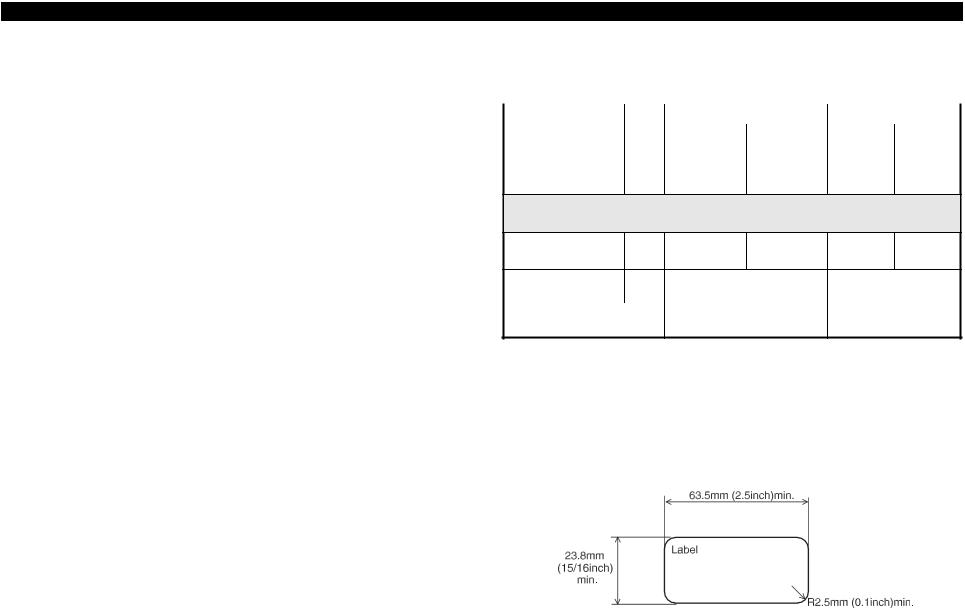
Table 1-13. Labels (FX-890)
FX-890 |
|
|
Bottom/Front Entry |
|
Rear Entry |
|||||
|
|
Minimum |
|
|
Maximum |
|
Minimum |
|
Maximum |
|
|
|
|
|
|
|
|
||||
|
|
|
|
|
|
|
|
|
|
|
Label size |
|
|
See Figure 1-1 below. |
|
----- |
|||||
|
|
|
|
|
|
|
|
|
|
|
Base sheet width |
(inch) |
|
(4) |
|
|
(10) |
|
----- |
|
----- |
|
(mm) |
|
101.6 |
|
|
254 |
|
|
|
|
|
|
|
|
|
|
|
|
|
|
|
Base sheet length |
(inch) |
|
(4) |
|
|
(22) |
|
----- |
|
----- |
(one page) |
(mm) |
|
101.6 |
|
|
558.8 |
|
|
|
|
|
|
|
|
|
|
|
|
|
|
|
Base sheet |
(inch) |
|
(0.0028) |
|
|
(0.0035) |
|
----- |
|
----- |
Thickness |
(mm) |
|
0.07 |
|
|
0.09 |
|
|
|
|
|
|
|
|
|
|
|
|
|
|
|
|
|
|
|
|
|
|
|
|
|
|
Total thickness |
(inch) |
|
(0.0063) |
|
|
(0.0075) |
|
----- |
|
----- |
|
(mm) |
|
0.16 |
|
|
0.19 |
|
|
|
|
|
|
|
|
|
|
|
|
|
|
|
Label weight |
(g/m2) |
|
64 |
|
|
----- |
||||
|
(lb) |
|
(17) |
|
|
|
|
|
||
|
|
|
|
|
|
|
|
|
|
|
Quality |
|
|
Plain paper or the same quality |
|
----- |
|||||
|
|
|
labels |
|
|
|
|
|
||
|
|
|
|
|
|
|
|
|
|
|
Note 1: Printing on labels is available only under normal temperature and humidity conditions.
2:The base sheet of labels must be continuous paper.
3:Labels should be inserted from bottom or front entrance.
4:Do not pull out paper from backward.
5:No label paper should be left on the printer when the printer is not used.
6:Do not print on the base sheet of labels.
7:Do not use cut sheet labels.
Revision B
Table 1-14. Labels (FX-2190)
|
FX-2190 |
|
Bottom/Front Entry |
Rear Entry |
|
||
|
|
|
|
|
|
|
|
|
Minimum |
Maximum |
Minimum |
Maximum |
|
||
|
|
|
|
||||
|
|
|
|
|
|
|
|
|
Label size |
|
See Figure 1-1 below. |
----- |
|
||
|
|
|
|
|
|
|
|
|
Base sheet width |
(inch) |
(4) |
(16) |
----- |
----- |
|
|
|
(mm) |
101.6 |
406.4 |
|
|
|
|
|
|
|
|
|
|
|
|
Base sheet length |
(inch) |
(4) |
(22) |
----- |
----- |
|
|
(one page) |
(mm) |
101.6 |
558.8 |
|
|
|
Base sheet |
(inch) |
(0.0028) |
(0.0035) |
----- |
----- |
Thickness |
(mm) |
0.07 |
0.09 |
|
|
|
|
|
|
|
|
Total thickness |
(inch) |
(0.0063) |
(0.0075) |
----- |
----- |
|
(mm) |
0.16 |
0.19 |
|
|
|
Label weight |
(g/m2) |
64 |
----- |
|
|
|
(lb) |
(17) |
|
|
|
|
|
|
|
|
|
Quality |
|
Plain paper or the same quality |
----- |
|
|
|
|
labels |
|
|
Note1: Printing on labels is available only under normal temperature and humidity conditions.
2:The base sheet of labels must be continuous paper.
3:Labels should be inserted from bottom or front entrance.
4:Don’t pull out paper from backward.
5:No label paper should be left on the printer when the printer is not used.
6:Don’t print on the base sheet of labels.
7:Don't use cut sheet labels.
Figure 1-1. Label Size
Manualsbooks.Com

EPSON FX-890/2190
Table 1-15. Roll Paper
FX-890& |
|
|
Bottom/Front Entry |
|
Rear Entry |
|||||
FX-2190 |
|
|
Minimum |
|
Maximum |
|
Minimum |
|
|
Maximum |
|
|
|
|
|
|
|
|
|
|
|
Width |
(inch) |
|
|
----- |
|
|
(8.5) |
|||
|
(mm) |
|
|
|
|
|
|
216 |
||
|
|
|
|
|
|
|
|
|
|
|
Length |
(inch) |
|
|
----- |
|
|
----- |
|||
|
(mm) |
|
|
|
|
|
|
|
|
|
|
|
|
|
|
|
|
|
|
|
|
Diameter |
(inch) |
|
|
----- |
|
|
(5) |
|||
|
(mm) |
|
|
|
|
|
127 mm |
|||
|
|
|
|
|
|
|
|
|
|
|
Thickness |
(inch) |
|
|
----- |
|
(0.0028) |
|
|
(0.0035) |
|
|
(mm) |
|
|
|
|
|
0.07 |
|
|
0.09 |
|
|
|
|
|
|
|
|
|
|
|
Weight |
(g/m2) |
|
|
----- |
|
52 |
|
|
82 |
|
|
(lb) |
|
|
|
|
|
(14) |
|
|
(22) |
|
|
|
|
|
|
|
|
|
|
|
Quality |
|
|
|
----- |
|
Plain paper, not curled, not |
||||
|
|
|
|
|
folded, not crumpled |
|||||
|
|
|
|
|
|
|
||||
|
|
|
|
|
|
|
|
|
|
|
Note1: Roll paper must be set on the roll paper holder (option).
2:Roll paper should be inserted from rear entrance only.
3:Release lever position should be friction.
TYPEFACE
Bit map font |
|
|
|
EPSON Draft |
: 10 cpi, 12 cpi, 15 cpi |
|
EPSON Roman |
: 10 cpi, 12 cpi, 15 cpi, Proportional |
|
EPSON Sans Serif |
: 10 cpi, 12 cpi, 15 cpi, Proportional |
|
EPSON OCR-B |
: 10 cpi * |
Bar code fonts:
EAN-13, EAN-8, Interleaved 2 of 5, UPC-A, UPC-E, Code 39, Code 128, POSTNET, Coda bar (NW-7)*, Industrial 2 of 5*, Matrix 2 of 5*
NOTE: “*”: These fonts are not described in user’s manual.
Manualsbooks.Com
Revision B
CHARACTER TABLES
Standard version |
: 13 tables |
NLSP version |
: 42 tables |
International character sets |
: 13 countries |
INPUT BUFFER
128 Kbyte

EPSON FX-890/2190
ELECTRICAL SPECIFICATION
|
Table 1-16. 120V Version |
|
|
|
|
Rated voltage |
|
AC 120 V |
|
|
|
Input voltage range |
|
AC 103.5 to 132 V |
|
|
|
Rated frequency range |
|
50 to 60 Hz |
|
|
|
Input frequency range |
|
49.5 to 60.5 Hz |
|
|
|
Rated current |
|
1.1 A (Max. 2.5 A) |
|
|
|
|
|
Approx.53 W (ISO/IEC 10561 Letter pattern) |
Power consumption |
|
Approx. 3.5 W in sleep mode * |
|
0 W in power off mode |
|
|
|
|
|
|
Energy Star compliant |
|
|
|
Insulation resistance |
|
10 M min. (between AC line and chassis, DC 500 V) |
|
|
|
Dielectric strength |
|
AC 1000 V rms. 1 min. or AC 1200 V rms. 1 sec. |
|
(between AC line and chassis) |
|
|
|
|
|
|
|
|
Table 1-17. 230V Version |
|
|
|
|
Rated voltage range |
|
AC 220 to 240 V |
|
|
|
Input voltage range |
|
AC 198 to 264 V |
|
|
|
Rated frequency range |
|
50 to 60 Hz |
|
|
|
Input frequency range |
|
49.5 to 60.5 Hz |
|
|
|
Rated current |
|
0.6 A (Max. 1.3A) |
|
|
|
|
|
Approx. 53 W (ISO/IEC 10561 Letter pattern) |
Power consumption |
|
Approx. 3.5 W in sleep mode * |
|
0 W in power off mode |
|
|
|
|
|
|
Energy Star compliant |
|
|
|
Insulation resistance |
|
10 M min. (between AC line and chassis, DC 500 V) |
|
|
|
Dielectric strength |
|
AC 1500 V rms. 1 min. (between AC line and chassis) |
|
|
|
Revision B
|
Table 1-18. UPS Version |
|
|
|
|
Rated voltage range |
AC 100 to AC240V |
|
|
|
|
Input voltage range |
AC 90 to 264V |
|
|
|
|
Rated frequency range |
50 to 60 Hz |
|
|
|
|
Input frequency range |
49.5 to 60.5 Hz |
|
|
|
|
Rated current |
1.1 A (Max. 3.0 A) |
|
|
|
|
|
Approx.56 W (ISO/IEC 10561 Letter pattern) |
|
Power consumption |
Approx. 4.0 W in sleep mode * |
|
0 W in power off mode |
||
|
||
|
Energy Star compliant |
|
|
|
|
Insulation resistance |
10 M min. (between AC line and chassis, DC 500 V) |
|
|
|
|
Dielectric strength |
AC 1500 V rms. 1 min. ( between AC line and chassis) |
|
|
|
Note “*” : Upon a lapse of 5 minutes under the following conditions, the printer enters sleep mode:
•Not in Pause, not in error status
•There is no data in input buffer.
PRODUCT DESCRIPTIONS |
Features |
17 |

EPSON FX-890/2190
ACOUSTIC NOISE
Level: 55 dB(A) (ISO 7779 pattern)
ENVIRONMENTAL CONDITIONS
Temperature : |
5 to 35 C (operating, *1) |
|
15 to 25 C (operating, *1,*2) |
|
-30 to 60 C (non-operating) |
Humidity : |
10 to 80 % RH (operating, *1) |
|
30 to 60 % RH (operating, *1,*2) |
|
0 to 85 % RH (non-operating) |
Resistance to shock : |
1 G, within 1ms (operating) |
|
2 G, within 2ms (non-operating) |
Resistance to vibration : |
0.25 G, 10 to 55 Hz (operating) |
|
0.50 G, 10 to 55 Hz (non-operating) |
*1: without condensation
*2: during printing on reclaimed paper, multi part paper, envelope, label or roll paper
RELIABILITY
Total print volume (MVBF) |
52 million lines (except print head) |
MTBF |
20000 POH (25% Duty) |
Print head life |
400 million strokes/wire |
|
(Approx. 400 million characters (Draft 10 cpi, 14 dots/ |
|
character)) |
|
|
RIBBON CARTRIDGE |
|
|
|
<FX-890>
Type |
Fabric |
Revision B
Color |
Black |
Ribbon dimensions |
13 mm (W) x 17 M (L) Endless |
Ribbon life |
Approximately 7.5 million characters |
|
(Draft 10 cpi, 14 dots / character) |
Cartridge dimensions |
287 mm (W) x 30 mm (H) x 77 mm (D) |
<FX-2190> |
|
Type |
Fabric |
Color |
Black |
Ribbon dimensions |
13 mm (W) x 19 M (L) Endless |
Ribbon life |
Approximately 12 million characters |
|
(Draft 10 cpi, 14 dots / character) |
Cartridge dimensions |
468.5 mm (W) x 34 mm (H) x 78 mm (D) |
SAFETY APPROVALS
120 V version |
|
|
|
Safety standards |
UL 1950, CSA C22.2 No. 950 |
|
EMI |
FCC part 15 subpart B class B, CSA C108.8 class B |
230 V version |
|
|
|
Safety standards |
EN60950 |
|
EMI |
EN55022 ( CISRP pub.22 ) class B |
|
|
AS/NZS.3548 class B |
UPS Version |
|
|
|
Safety standards |
UL 1950, CSA C22.2 No. 950 |
|
|
EN60950 |
|
EMI |
FCC part 15 subpart B class B, CSA C108.8 class B |
|
|
EN55022 (CISPR pub. 22) class B |
|
|
AS/NZS 3548 class B |
PRODUCT DESCRIPTIONS |
Features |
18 |

EPSON FX-890/2190
CE MARKING
230 V version & UPS version
Low Voltage Directive 73/23/EEC: EN60950
EMC Directive 89/336/EEC: |
EN55022 class B |
|
EN61000-3-2 |
EN61000-3-3
EN55024
INTERFACE
Bi-directional parallel interface (IEEE-1284 nibble mode supported)
USB (ver1.1) I/F
Type-B I/F level 2 (Option)
CONTROL CODE
ESC/P
IBM PPDS emulation
|
|
|
|
|
Revision B |
|
|
|
|
|
|
EXPENDABLES & OPTIONS |
|
|
|
|
|
|
|
|
|
||
|
Table 1-19. Expendables & Option |
|
|
||
|
|
|
|
|
|
|
Expendables |
|
Code No. |
||
|
|
|
FX-890 |
|
FX-2190 |
|
Ribbon cartridge (Black) |
|
S015329 |
|
S015327 |
|
|
|
|
|
|
|
Options |
|
|
|
|
|
|
|
|
|
|
|
High capacity cut sheet feeder (Bin 1) |
|
C80638* |
|
C80640* |
|
|
|
|
|
|
|
Single bin cut sheet feeder (Bin 2) |
|
C80637* |
|
C80639* |
|
|
|
|
|
|
|
Pull tractor unit |
|
C80020* |
|
C80021* |
|
|
|
|
|
|
|
Roll paper holder |
|
#8310 |
|
#8310 |
|
|
|
|
|
|
|
Front sheet guide |
|
C81400* |
|
C81401* |
|
|
|
|
|
|
|
Front paper guide |
|
C81402* |
|
C81403* |
|
|
|
|
|
|
|
Serial Interface card |
|
C82305* / C82306* |
|
C82305* / C82306* |
|
|
|
|
|
|
|
32KB intelligent serial Interface card |
|
C82307* / C82308* |
|
C82307* / C82308* |
|
|
|
|
|
|
|
Local Talk I/F card |
|
C82312* |
|
C82312* |
|
|
|
|
|
|
|
32KB IEEE-488 I/F card |
|
C82313* |
|
C82313* |
|
|
|
|
|
|
|
Coax I/F card |
|
C82314* |
|
C82314* |
|
|
|
|
|
|
|
Twinax I/F card |
|
C82315* |
|
C82315* |
|
|
|
|
|
|
|
IEEE-1284 parallel I/F card |
|
C82345* |
|
C82345* |
|
|
|
|
|
|
|
EpsonNet 10 Base 2/T Int. Print Server |
|
C82362* |
|
C82362* |
|
|
|
|
|
|
|
EpsonNet 10/100 Base Tx Int. Print Server |
|
C82363* *1/C82364* |
|
C82363* *1/C82364* |
|
|
|
|
|
|
|
EpsonNet 10/100 Base Tx Int. Print Server |
|
C82384* |
|
C82384* |
|
|
|
|
|
|
|
EpsonNet 10/100 Base Tx Int. Print Server 2 |
|
C82391* |
|
C82391* |
|
|
|
|
|
|
|
EpsonNet 802.11b Wireless Ext. Print Server |
|
C12C82396* |
|
C12C82396* |
|
|
|
|
|
|
Note “*1”: When you use Ethernet interface card C82363*, you need to attach the optional interface adapter (C82525*) to the interface card.
PRODUCT DESCRIPTIONS |
Features |
19 |

EPSON FX-890/2190
PRINTABLE AREA
Cut sheets
Printable Area
|
|
|
|
|
Revision B |
|
Table 1-20. Printable Area for Cut Sheet |
||||
|
|
|
|
|
|
|
|
|
Single Sheet / Multi Part |
||
|
|
|
|
|
|
|
|
|
FX-890 |
|
FX-2190 |
|
|
|
|
|
|
PW (Width) |
|
|
Refer to “PAPER |
|
Refer to “PAPER |
|
|
|
SPECIFICATIONS” Table 1-3 on |
|
SPECIFICATIONS” Table 1-4 on |
|
|
|
page 10 for single sheet or |
|
page 11 for single sheet or |
PL (Length) |
|
|
|
||
|
|
Table 1-5 on page 11 for multi |
|
Table 1-6 on page 12 for multi |
|
|
|
|
|
||
|
|
|
part |
|
part |
|
|
|
|
|
|
LM (Left Margin) |
|
|
3 mm or more (PW<=209.2 mm) |
|
3 mm or more (PW<=351.4 mm) |
|
|
|
|
||
|
|
|
26.9 mm or more (PW=257 mm) |
|
37.3 mm or more (PW=420 mm) |
RM (Right Margin) |
|
|
|
||
|
|
|
|
|
|
TM (Top Margin) |
|
|
4.2 mm or more |
||
|
|
|
|||
BM (Bottom Margin) |
|
||||
|
|
|
|
||
|
|
|
|
|
|
Note : The maximum horizontal printable area is 203.2 mm (8 inch) for FX-890 or 345.4 mm (13.6 inch) for FX-2190.
Figure 1-2. Printable Area for Cut Sheet
PRODUCT DESCRIPTIONS |
Features |
20 |
EPSON FX-890/2190
Envelope
Printable Area |
Figure 1-3. Printable Area for Envelope
Table 1-21. Printable Area for Envelope
Envelope Printable Area
PW (Width)
PL (Length)
Refer to “PAPER SPECIFICATIONS” Table 1-8 on page 13
LM (Left Margin)
RM (Right Margin)
3 mm or more
TM (Top Margin)
BM (Bottom Margin)
4.2 mm or more
Revision B
Continuous paper
PW
LM |
|
|
RM |
|
|
|
|
|
|
|
|
|
|
|
TM
PL |
|
Printable Area |
|
||
|
|
|
|
|
|
BM
Figure 1-4. Printable Area for Continuous Paper
Table 1-22. Printable Area for Continuous Paper
|
|
Continuous Paper |
||
|
|
|
|
|
|
|
FX-890 |
|
FX-2190 |
|
|
|
|
|
PW (Width) |
|
Refer to “PAPER |
|
Refer to “PAPER |
|
|
SPECIFICATIONS” Table 1-11 |
|
SPECIFICATIONS” Table 1-12 |
PL (Length) |
|
|
||
|
on page 14 |
|
on page 14 |
|
|
|
|
||
|
|
|
|
|
LM (Left Margin) |
|
13 mm or more (PW<=241.3mm, |
|
13 mm or more (PW<=377.8mm, |
|
|
9.5 inches) |
|
14.875 inches) |
RM (Right Margin) |
|
|
||
|
|
|
|
|
|
|
26 mm or more (PW=254 mm, |
|
26 mm or more (PW=406.4 mm, |
|
|
10 inches) |
|
16 inches) |
|
|
|
|
|
TM (Top Margin) |
|
4.2 mm or more |
||
|
|
|||
BM (Bottom Margin) |
|
|||
|
||||
|
|
|
|
|
|
|
|
|
|
PRODUCT DESCRIPTIONS |
Features |
21 |

EPSON FX-890/2190
Label
1.2 mm |
|
PW |
or more |
TM LM |
RM |
|
PL |
Printable area |
|
BM |
|
|
6.35mm |
|
|
or more |
|
Figure 1-5. Printable Area for Label
Table 1-23. Printable Area for Label
|
|
Continuous Paper |
||
|
|
|
|
|
|
|
FX-890 |
|
FX-2190 |
|
|
|
|
|
|
PW (Width) |
Refer to “PAPER |
|
Refer to “PAPER |
|
|
SPECIFICATIONS” Table 1-13 |
|
SPECIFICATIONS” Table 1-14 |
|
PL (Length) |
|
||
|
on page 15 |
|
on page 15 |
|
|
|
|
||
|
|
|
|
|
LM (Left Margin)
RM (Right Margin)
3 mm or more
TM (Top Margin)
BM (Bottom Margin)
Roll paper
TM
Revision B
|
PW |
LM |
RM |
Printable area
Figure 1-6. Printable Area for Roll Paper |
||
Table 1-24. Printable Area for Roll Paper |
||
|
|
|
|
|
Roll Paper |
|
|
|
PW (Width) |
|
Refer to “PAPER SPECIFICATIONS” Table 1-15 on page 16 |
|
|
|
PL (Length) |
|
----- |
|
|
|
LM (Left Margin) |
|
3 mm or more |
|
|
|
RM (Right Margin) |
|
3 mm or more |
|
|
|
TM (Top Margin) |
|
4.2 mm or more |
|
|
|
BM (Bottom Margin) |
|
----- |
|
|
|
PRODUCT DESCRIPTIONS |
Features |
22 |

EPSON FX-890/2190
1.2 Interface
This printer provides bi-directional 8-bit parallel interface, USB interface and Type-B optional interface slot as standard.
1.2.1 Parallel interface (Forward channel)
Specifications
|
Transmission mode: |
8 bit parallel, IEEE-1284 compatibility mode |
|
Adaptable connector: |
57-30360 (Amphenol) or equivalent |
|
Synchronization: |
-STROBE pulse |
Handshaking : BUSY and -ACKNLG signals
Signal level: |
TTL compatible (IEEE-1284 level 1 device) |
Table 1-25. Connector pin assignment (Forward channel)
Pin |
|
Signal |
|
Return |
|
IN/ |
|
|
|
|
|
GND |
|
|
Function description |
|
|||
No. |
|
Name |
|
|
Out* |
|
|
||
|
|
Pin |
|
|
|
|
|||
|
|
|
|
|
|
|
|
|
|
1 |
|
-STROBE |
|
19 |
|
In |
|
Strobe pulse. Input data is latched at falling edge of |
|
|
|
|
|
the signal. |
|
||||
|
|
|
|
|
|
|
|
|
|
|
|
|
|
|
|
|
|
|
|
2 |
|
DATA1 |
|
20 |
|
In |
|
Parallel input data to the printer. |
bit 0: LSB |
|
|
|
|
|
|
|
|
|
|
3 |
|
DATA2 |
|
21 |
|
In |
|
|
bit 1 |
|
|
|
|
|
|
|
|
|
|
4 |
|
DATA3 |
|
22 |
|
In |
|
|
bit 2 |
|
|
|
|
|
|
|
|
|
|
5 |
|
DATA4 |
|
23 |
|
In |
|
|
bit 3 |
|
|
|
|
|
|
|
|
|
|
6 |
|
DATA5 |
|
24 |
|
In |
|
|
bit 4 |
|
|
|
|
|
|
|
|
|
|
7 |
|
DATA6 |
|
25 |
|
In |
|
|
bit 5 |
|
|
|
|
|
|
|
|
|
|
8 |
|
DATA7 |
|
26 |
|
In |
|
|
bit 6 |
|
|
|
|
|
|
|
|
|
|
9 |
|
DATA8 |
|
27 |
|
In |
|
|
bit 7: MSB |
|
|
|
|
|
|
|
|
|
|
|
|
|
|
|
|
|
|
This signal (negative pulse) indicates that the |
|
10 |
|
-ACKNLG |
|
28 |
|
Out |
|
printer has received data and is ready to accept next |
|
|
|
|
|
|
|
|
|
one. |
|
|
|
|
|
|
|
|
|
|
|
11 |
|
BUSY |
|
29 |
|
Out |
|
This signal’s high level means that the printer is not |
|
|
|
|
|
ready to accept data. |
|
||||
|
|
|
|
|
|
|
|
|
|
|
|
|
|
|
|
|
|
|
|
Revision B
Table 1-25. Connector pin assignment (Forward channel) (continued)
Pin |
|
Signal |
|
Return |
|
IN/ |
|
|
|
|
GND |
|
|
Function description |
|||
No. |
|
Name |
|
|
Out* |
|
||
|
|
Pin |
|
|
|
|||
|
|
|
|
|
|
|
|
|
12 |
|
PE |
|
28 |
|
Out |
|
This signal’s high level means that the printer is in |
|
|
|
|
a state of paper-out error. |
||||
|
|
|
|
|
|
|
|
|
|
|
|
|
|
|
|
|
|
13 |
|
SLCT |
|
28 |
|
Out |
|
Always at high level when the power to the printer |
|
|
|
|
is on. |
||||
|
|
|
|
|
|
|
|
|
|
|
|
|
|
|
|
|
|
14 |
|
-AFXT |
|
30 |
|
In |
|
Not used. |
|
|
|
|
|
|
|
|
|
31 |
|
-INIT |
|
30 |
|
In |
|
This signal’s negative pulse initializes printer. |
|
|
|
|
|
|
|
|
|
32 |
|
-ERROR |
|
29 |
|
Out |
|
This signal’s low level means the printer is in a |
|
|
|
|
state of error. |
||||
|
|
|
|
|
|
|
|
|
|
|
|
|
|
|
|
|
|
36 |
|
-SLIN |
|
30 |
|
In |
|
Not used. |
|
|
|
|
|
|
|
|
|
18 |
|
Logic H |
|
- |
|
Out |
|
This line is pulled up to +5 V through 3.9 k |
|
|
|
|
resistor. |
||||
|
|
|
|
|
|
|
|
|
|
|
|
|
|
|
|
|
|
35 |
|
+5 V |
|
- |
|
Out |
|
This line is pulled up to +5 V through 1.0 k |
|
|
|
|
resistor. |
||||
|
|
|
|
|
|
|
|
|
|
|
|
|
|
|
|
|
|
17 |
|
Chassis |
|
- |
|
- |
|
Chassis GND. |
|
|
|
|
|
|
|
|
|
16, 33 |
|
GND |
|
- |
|
- |
|
Signal GND. |
19-30 |
|
|
|
|
||||
|
|
|
|
|
|
|
|
|
|
|
|
|
|
|
|
|
|
15, 34 |
|
NC |
|
- |
|
- |
|
Not connected. |
|
|
|
|
|
|
|
|
|
Note : In/Out shows the direction of signal flow from the printer’s point of view.
PRODUCT DESCRIPTIONS |
Interface |
23 |

EPSON FX-890/2190
Data transmission timing
DATA |
|
|
|
|
data byte n |
|
|
|
|
|
|
|
|
|
|
|
data byte n+1 |
||||||
|
|
|
|
|
|
|
|
|
|
|
|
|
|
|
|
|
|
|
|
|
|
|
|
|
|
|
|
|
|
|
t hold |
|
|
|
|
|
|
|
|
|
|
||||||
|
|
|
|
|
|
|
|
|
|
|
|
|
|
|
|
|
|
|
|
|
|
|
|
-STROBE |
|
|
|
|
|
|
|
|
|
|
|
|
|
|
|
|
|
|
|
||||
|
|
|
|
|
|
|
|
|
|
|
|
|
|
|
|
|
t next |
|
|
|
|||
|
|
|
t setup |
|
|
t stb |
|
|
|
|
|
|
|||||||||||
|
|
|
|
|
|
|
|
|
|
||||||||||||||
BUSY |
|
|
|
|
|
|
|
|
|
|
|
|
|
|
|
|
|
|
|
||||
|
|
|
t ready |
|
t busy |
|
|
|
|
|
|
|
|
|
|
||||||||
-ACKNLG |
|
|
|
|
|
|
|
|
|
|
|
|
|
|
|
|
|
|
|
|
|
||
|
|
|
|
|
|
|
|
|
|
|
|
|
|
|
|
|
|
|
|
|
|||
|
|
|
|
|
|
|
|
|
|
|
|
|
|
|
|
|
|
|
|
|
|||
|
|
|
|
|
|
|
t reply |
|
|
|
t ack |
|
|
||||||||||
|
|
|
|
|
|
|
|
|
|
|
|
|
|
|
|
|
t nbusy |
||||||
|
|
Figure 1-7. Data transmission timing |
|||||||||||||||||||||
|
|
|
Table 1-26. Parameters |
|
|
|
|
|
|
|
|
|
|
||||||||||
|
|
|
|
|
|
|
|
|
|
||||||||||||||
|
|
Parameter |
|
|
Minimum |
|
|
Maximum |
|
||||||||||||||
|
|
|
|
|
|
|
|
|
|
|
|
|
|
|
|
|
|
|
|
|
|
|
|
|
|
t setup |
|
|
500 nsec |
|
_ |
|
|
|
|
|
|
|
|||||||||
|
|
|
|
|
|
|
|
|
|
|
|
|
|
|
|||||||||
|
|
t hold |
|
|
500 nsec |
|
|
|
_ |
|
|
|
|
|
|
|
|||||||
|
|
|
|
|
|
|
|
|
|
|
|
|
|
|
|
|
|
|
|
|
|
|
|
|
|
t stb |
|
|
500 nsec |
|
|
|
_ |
|
|
|
|
|
|
|
|||||||
|
|
|
|
|
|
|
|
|
|
|
|
|
|
|
|
|
|
|
|||||
|
|
t ready |
|
0 |
|
|
|
|
|
|
_ |
|
|
|
|
|
|
|
|||||
|
|
|
|
|
|
|
|
|
|
|
|
|
|
|
|
|
|
|
|
|
|
|
|
|
|
t busy |
|
_ |
|
|
|
|
|
|
|
500 nsec |
|
|
|||||||||
|
|
|
|
|
|
|
|
|
|
|
|
|
|
|
|
|
|
|
|||||
|
|
t reply |
|
_ |
|
|
|
|
|
|
_ |
|
|
|
|
|
|
|
|||||
|
|
|
|
|
|
|
|
|
|
|
|
|
|
|
|
|
|
|
|
|
|
|
|
|
|
t ack |
|
|
500 nsec |
|
|
|
|
10 us |
|
|
|||||||||||
|
|
|
|
|
|
|
|
|
|
|
|
|
|
|
|
|
|
|
|||||
|
|
t nbusy |
|
0 |
|
|
|
|
|
|
_ |
|
|
|
|
|
|
|
|||||
|
|
|
|
|
|
|
|
|
|
|
|
|
|
|
|
|
|
|
|
|
|
|
|
|
|
t next |
|
0 |
|
|
|
|
|
|
_ |
|
|
|
|
|
|
|
|||||
|
|
|
|
|
|
|
|
|
|
|
|
|
|
||||||||||
|
|
t tout*1 |
|
_ |
|
|
|
|
|
|
|
120 nsec |
|
|
|||||||||
|
|
|
|
|
|
|
|
|
|
|
|
|
|
|
|
|
|
|
|
|
|
|
|
|
|
t tin*2 |
|
_ |
|
|
|
|
|
|
|
200 nsec |
|
|
|||||||||
Note “*1”: Rise and fall time of output signals “*2” : Rise and fall time of input signals
Revision B
BUSY signal is active (high level) under any of the following conditions:
In the process of receiving data
Input buffer full
-INT signal active (low level)
During hardware initialization
-ERROR or PE signal active (low level or high level, respectively)
In the self test mode
In the adjustment mode
In the default-setting mode
-ERROR signal is active (low level) under any of the following conditions:
In the condition of the printer hardware error (fatal error)
In the condition of the paper-out error
In the condition of the release lever error
In the condition of the cover open error
In the condition of the paper eject error
PE signal is active (high level) under the following condition:
In the condition of paper-out error
PRODUCT DESCRIPTIONS |
Interface |
24 |

EPSON FX-890/2190
1.2.2 Parallel interface (Reverse channel)
Specifications
|
Transmission mode : |
IEEE-1284 nibble mode |
|
Adaptable connector: |
57-30360 (Amphenol) or equivalent |
Synchronization : Refer to the IEEE-1284 specification
Handshaking : Refer to the IEEE-1284 specification
Signal level: |
TTL compatible (IEEE-1284 level 1 device) |
Data transmission timing : Refer to the IEEE-1284 specification
Extensibility request : The printer responds to the extensibility request in
the affirmative, when the request is 00H or 04H, which mean;
00H : Request nibble mode of reverse channel transfer
04H : Request device ID in nibble mode of reverse channel transfer
Device ID: The printer sends the following device ID string when it is requested
FX-890
When IEEE1284.4 is enabled,
[00H][4CH]
MFG:EPSON;
CMD:ESCP9,PRPII9,BDC,D4; MDL:FX-890; CLS:PRINTER; DES:EPSON[SP]FX-890;
When IEEE1284.4 is disabled,
[00H][49H]
MFG:EPSON;
CMD:ESCP9,PRPII9,BDC; MDL:FX-890; CLS:PRINTER; DES:EPSON[SP]FX-890;
Revision B
FX-2190
When IEEE1284.4 is enabled,
[00H][4EH]
MFG:EPSON;
CMD:ESCP9,PRPII9,BDC,D4; MDL:FX-2190; CLS:PRINTER; DES:EPSON[SP]FX-2190;
When IEEE1284.4 is disabled,
[00H][4BH]
MFG:EPSON;
CMD:ESCP9,PRPII9,BDC; MDL:FX-2190; CLS:PRINTER; DES:EPSON[SP]FX-2190;
PRODUCT DESCRIPTIONS |
Interface |
25 |

EPSON FX-890/2190 |
Revision B |
Table 1-27. Connector pin assignment (Reverse channel)
1.2.3 USB Interface
|
|
Return |
IN/ |
|
|
Specifications |
|
|
||
Pin No. |
Signal Name |
GND |
Function description |
|
|
|
|
|
|
|
Out* |
|
|
Standard: |
|
Based on |
|||||
|
|
Pin |
|
|
|
|||||
|
|
|
|
|
|
|
||||
|
|
|
|
|
|
|
|
|
|
|
1 |
HostClk |
19 |
In |
Host clock signal. |
|
|
|
|
|
“Universal Serial Bus Specifications |
|
|
|
|
|
Revision 1.1” |
|||||
2 |
DATA1 |
20 |
In |
Parallel input data to the printer. |
bit 0: LSB |
|
|
|
|
|
|
|
|
|
“Universal Serial Bus Device Class |
||||||
|
|
|
|
|
|
|
|
|
|
|
3 |
DATA2 |
21 |
In |
|
bit 1 |
|
|
|
|
Definition for Printing Devices Version 1.1” |
4 |
DATA3 |
22 |
In |
|
bit 2 |
|
Bit rate : |
|
12 Mbps (Full Speed Device) |
|
|
|
|
|
|
|
|
||||
5 |
DATA4 |
23 |
In |
|
bit 3 |
|
Data encording : |
NRZI |
||
6 |
DATA5 |
24 |
In |
|
bit 4 |
|||||
|
|
|
|
|
|
|||||
7 |
DATA6 |
25 |
In |
|
bit 5 |
|
Adaptable connector : |
USB Series B |
||
|
|
|
|
|
|
|||||
8 |
DATA7 |
26 |
In |
|
bit 6 |
|
Recommended cable length : 2 meters |
|||
9 |
DATA8 |
27 |
In |
|
bit 7: MSB |
Connector pin assignment and signals : |
||||
10 |
PtrClk |
28 |
Out |
Printer clock signal. |
|
|
|
Table 1-28. Connector pin assignment |
||
11 |
PtrBusy / |
29 |
Out |
Printer busy signal and reverse channel transfer |
Pin No. |
Signal name |
In/Out |
Function description |
||
DataBit-3,7 |
data bit 3 or 7. |
|
|
|
|
|
|
|||
|
|
|
|
|
|
|
|
Cable power. Maximum power consumption is |
||
|
|
|
|
|
|
1 |
|
VCC |
- |
|
|
AckDataReq / |
|
|
Acknowledge data request signal and reverse |
|
100mA |
||||
12 |
28 |
Out |
|
|
|
|
||||
DataBit-2,6 |
channel transfer data bit 2 or 6. |
|
|
|
|
|
|
|||
|
|
|
|
2 |
|
-Data |
Bi-directional |
Data |
||
|
|
|
|
|
|
|
||||
13 |
Xflag / |
28 |
Out |
X-flag signal and reverse channel |
|
3 |
|
+Data |
Bi-directional |
Data, pull up to +3.3V via 1.5K resistor |
DataBit-1,5 |
transfer data bit 1 or 5. |
|
|
|||||||
|
|
|
|
|
|
|||||
|
|
|
|
4 |
|
Ground |
- |
Cable ground |
||
14 |
HostBusy |
30 |
In |
Host Busy signal. |
|
|
||||
|
|
|
|
|
|
|||||
31 |
-INIT |
30 |
In |
Not used. |
|
|
|
|
|
|
|
-DataAvail / |
|
|
Data Available signal and reverse channel transfer |
|
|
|
Pin #2 |
Pin #1 |
|
32 |
29 |
Out |
|
|
|
|
|
|||
DataBit-0,4 |
data bit 0 or 4. |
|
|
|
|
|
|
|||
|
|
|
|
|
|
|
|
|
||
36 |
1284-Active |
30 |
In |
1284 active signal. |
|
|
|
|
|
|
18 |
Logic-H |
- |
Out |
This line is pulled up to +5 V through 3.9 k |
|
|
|
|
|
|
resistor. |
|
|
|
|
|
|
||||
|
|
|
|
|
|
|
|
|
|
|
35 |
+5 V |
- |
Out |
This line is pulled up to +5 V through 1.0 k |
|
|
|
|
|
|
resistor. |
|
|
|
|
|
|
||||
|
|
|
|
|
|
|
|
|
|
|
17 |
Chassis |
- |
- |
Chassis GND. |
|
|
|
|
|
|
16, 33 |
GND |
- |
- |
Signal GND. |
|
|
|
|
Pin #3 |
Pin #4 |
19-30 |
|
|
|
|
||||||
|
|
|
|
|
|
|
|
|
|
|
15, 34 |
NC |
- |
- |
Not connected. |
|
|
|
|
|
|
|
|
|
|
|
|
|
|
Figure 1-8. USB Interface connector pin assignment |
||
Note : In/Out refers to the direction of signal flow from the printer’s point of view.
PRODUCT DESCRIPTIONS |
Interface |
26 |

EPSON FX-890/2190 |
Revision B |
1.2.4 Optional Interface
Type-B optional interface cards are available.
Table 1-29. FX-890
Reply message |
|
ESC/P |
|
IBM PPDS |
Main-Type |
|
MT9p, PW80c110cpi, |
|
MT9p, PW80c110cpi, |
|
PRG(Wxxxxx)rev, AP500ma |
|
PRG(Wxxxxx)rev, AP500ma |
|
|
|
|
||
|
|
|
|
|
Product-Name |
|
FX-890 |
|
FX-890 |
|
|
|
|
|
Emulation-Type |
|
ESCP9, PRPII9, BDC |
|
ESCP9, PRPII9, BDC |
|
|
|
|
|
Entity-Type |
|
EPSONFX |
|
EPSONPRPII9 |
|
|
|
|
|
Table 1-30. FX-2190
Reply message |
|
ESC/P |
|
IBM PPDS |
Main-Type |
|
MT9p, PW136c110cpi, |
|
MT9p, PW136c110cpi, |
|
PRG(Wxxxxx)rev, AP500ma |
|
PRG(Wxxxxx)rev, AP500ma |
|
|
|
|
||
|
|
|
|
|
Product-Name |
|
FX-2190 |
|
FX-2190 |
|
|
|
|
|
Emulation-Type |
|
ESCP9, PRPII9, BDC |
|
ESCP9, PRPII9, BDC |
|
|
|
|
|
Entity-Type |
|
EPSONFX |
|
EPSONPRPII9 |
|
|
|
|
|
1.2.5 Type-B Interface communication specification
Reply for Optional command
(*: Reply for Type-B I/F Level 2 device: not described in user's manual)
Table 1-31. Reply for Optional command
Option command |
Command name |
|
Reply-A |
|
Reply-B |
number |
|
|
|||
|
|
|
|
|
|
00h |
No-operation |
|
----- |
|
----- |
|
|
|
|
|
|
01h |
Start Hardware Reset |
|
Accept* |
|
Execute OK* |
|
|
|
|
|
|
02h |
Start Software Reset |
|
Reject |
|
----- |
|
|
|
|
|
|
03h |
Send Main System Type |
|
Accept |
|
Execute OK |
|
|
|
|
|
|
04h |
Send Name Data |
|
Reject |
|
----- |
|
|
|
|
|
|
05h |
Inquire Name Data |
|
Accept |
|
Execute OK |
|
|
|
|
|
|
06h |
Send Product Name |
|
Accept |
|
Execute OK |
|
|
|
|
|
|
07h |
Send Software Emulation Type |
|
Accept |
|
Execute OK |
|
|
|
|
|
|
08h |
Complete Buffered Data |
|
Accept |
|
Execute OK |
|
|
|
|
|
|
09h |
Stop Procedure |
|
Reject |
|
----- |
|
|
|
|
|
|
0Ah |
Return Buffered Data |
|
Reject |
|
----- |
|
|
|
|
|
|
0Bh |
Send Entity Type |
|
Accept |
|
Execute OK |
|
|
|
|
|
|
0Ch |
Send Status |
|
Accept |
|
Execute OK |
|
|
|
|
|
|
0Dh |
Quit Procedure |
|
Reject |
|
----- |
|
|
|
|
|
|
0Eh |
Inquire ASCII Message |
|
Reject |
|
----- |
|
|
|
|
|
|
0Fh |
Send ASCII Message |
|
Accept |
|
Execute OK |
|
|
|
|
|
|
10h |
(Reserved) |
|
Unknown |
|
----- |
|
|
|
|
|
|
11h |
Send All Entity Type |
|
Reject |
|
----- |
|
|
|
|
|
|
12h |
Inquire Protocol |
|
Reject |
|
----- |
|
|
|
|
|
|
13h |
(Reserved) |
|
Unknown |
|
----- |
|
|
|
|
|
|
14h |
Inquire Emergency Message |
|
Accept |
|
Execute OK |
|
|
|
|
|
|
15h |
Send Emergency Reply |
|
Accept |
|
Execute OK |
|
|
|
|
|
|
16h-17h |
(Reserved) |
|
Unknown |
|
----- |
|
|
|
|
|
|
PRODUCT DESCRIPTIONS |
Interface |
27 |

EPSON FX-890/2190
Main command
Table 1-32. Main command
Option command |
|
Command name |
|
|
Sending Timing |
|
number |
|
|
|
|||
|
|
|
|
|
|
|
|
|
|
|
|
• Init signal on the std. parallel |
|
01h |
|
Start Software Reset |
|
|
• Type-B I/F Option command : 01h |
|
|
|
|
• |
Panel Reset |
||
|
|
|
|
|
||
|
|
|
|
|
• |
Cold start |
|
|
|
|
|
|
|
02h |
|
Send Option Type |
|
|
• Deciding the level of Type-B I/F |
|
|
|
|
|
after power on |
||
|
|
|
|
|
|
|
04h |
|
Send Name Data |
|
|
• |
Type-B I/F Option command: 05h |
|
|
|
|
|
|
|
07h |
|
Inquire Software Emulation Type |
|
• |
Changing control language |
|
|
|
|
|
|||
|
|
|
|
|
|
|
0Eh |
|
Inquire ASCII Message |
|
• |
Writing to DBIN-register |
|
|
|
|
|
|
|
|
14h |
|
Inquire Emergency Reply |
|
• Reply for Back Ground Job |
||
|
|
|
command response |
|||
|
|
|
|
|
|
|
15h |
|
Send Emergency Message |
|
• Receive back Ground Job |
||
|
|
|
command |
|||
|
|
|
|
|
|
|
|
|
|
|
|
|
|
Back Ground Job command: |
Response |
|
|
|
||
“0x00”: get device |
ID Normal response |
|||||
“0x01”: get all status |
Normal response |
|||||
“0x02”~“0x3F” |
Processing impossible response |
|||||
A bit rate available by Serial I/F card :
19200bps, 9600bps, 4800bps, 2400bps, 1200bps, 600bps, 300bps
Revision B
1.2.6 Interface selection
The printer has 3 interfaces; the parallel interface, USB interface and Type-B optional interface. These interfaces are selected manually by Default Setting or selected automatically.
Manual selection
One of the three interfaces can be selected by Default Setting.
Automatic selection
The automatic interface selection is enabled by Default Setting. In this automatic interface selection mode, the printer is initialized to the idle state scanning which interface receives data at power-on. Then the interface that receives data first is selected. When the host stops data transfer and the printer is in the stand-by state for the period of seconds specified by Default Setting, the printer is returned to the idle state. As long as the host sends data or the printer interface is the busy state, the selected interface is let as it is.
Interface state and interface selection
When the parallel interface is not selected, the interface gets info a busy state. When the Type-B serial interface card is installed and it is not selected, the interface sends XOFF and sets the DTR signal MARK. When the optional interface is not selected, the printer sets “OFFLINE” bit of MNSTS register to the optional interface. When the printer is initialized or returned to the idle state, the parallel interface got into a ready state, the serial interface sends XON and sets the
DTR SPACE and the printer resets “OFFLINE” bit of MNSTS register to the optional interface. Note that the interrupt signal such as a -INIT signal on the parallel interface is not effective while that interface is not selected.
Preventing Hosts from Data Transfer Timeout
Generally, hosts abandons data transfer to peripherals when a peripheral is in the busy state for dozens of seconds continuously. To prevent hosts from this kind of timeout, the printer receives data very slowly, several bytes per minute, even if the printer is in the busy state. This slowdown is started when the rest of the input buffer becomes several thousands of bytes. At last, when the input buffer is full, the printer is in the busy state continuously.
IEEE1284.4 on the parallel interface and on the USB interface do not require this function.
PRODUCT DESCRIPTIONS |
Interface |
28 |

EPSON FX-890/2190 |
Revision B |
1.2.7 IEEE1284.4 protocol
The packet protocol described by IEEE1284.4 is supported on the parallel I/F.
Two function modes of IEEE1284.4 protocol, “Off” and “Auto”, are available and one of them is selected according to the value of Default setting. (See Section 1.3.5. Default Setting).
NOTE:Packet protocol option “Off” &“Auto” in Default setting mode are effective in not only parallel I/F but also USB I/F.
Auto: Communication is carried out in the convetional mode until a magic string (1284.4 synchronous commands) is received. By receiving a magic string, communication in IEEE1284.4 packet mode is started.
Off: |
Communication is carried out in the convetional mode. |
NOTE:The packet protocol of IEEE1284.4 allows a device to carry on multiple exchanges or conversations which contain data and/or control information with another device at the same time across a single point-to-point link. The protocol is not, however, a device control language. It does provide basic transport-level flow control and multiplexing services. The multiplexed logical channels are independent of each other and blocking of one has no effect on the others. The protocol operates over IEEE1284.
PRODUCT DESCRIPTIONS |
Interface |
29 |

EPSON FX-890/2190
1.3 Operation
This section describes the operations on this printer.
1.3.1 Control panel
The control panel of this printer is equipped with 6 switches and 10 LEDs, which are located as shown below.
Figure 1-9. Control Panel
Revision B
1.3.2Switches
1.3.2.1Operation in Normal Mode
In the normal mode, pressing panel switches executes the following functions.
|
|
|
Table 1-33. Normal Mode |
|
|
|
|
Switch |
|
|
Function |
Pause |
|
• Alternates printing and no-printing status. |
|
|
• Enables Micro Adjust function, holding it down for 3 seconds. |
||
|
|
||
|
|
|
|
Load/Eject |
|
• Loads or ejects the paper. |
|
|
• Executes micro feed forward, when this function is enabled. |
||
|
|
||
|
|
• Executes line feed, pressing it shortly. |
|
LF/FF |
|
• Executes form feed, holding it down for a few seconds. |
|
|
|
• Executes micro feed backward, when this function is enabled. |
|
|
|
|
|
Tear Off/Bin |
|
• |
Advances continuous paper to the Tear-Off position. |
|
• Selects CSF bin 1/2 or Card mode in friction mode. |
||
|
|
||
Font |
|
• Selects font and draft quality. |
|
|
|
|
|
Pitch |
|
• |
Selects pitch. |
|
|
|
|
|
|
|
|
Reset (Font & Pitch) |
|
• |
Resets the printer. |
|
|
|
|
Menu |
|
• Enter or exit the default setting mode. |
|
|
|
||
(Pitch & Tear Off/Bin) |
|
|
|
|
|
|
|
PRODUCT DESCRIPTIONS |
Operation |
30 |
 Loading...