


 Loading...
SERVICE MANUAL
Large Format Color Inkjet Printer
SC-F6000 series
SC-B6000 series
Confidential
SEIJ12011
Notice:
All rights reserved. No part of this manual may be reproduced, stored in a retrieval system, or transmitted in any form or by any means, electronic, mechanical, photocopying, recording, or otherwise, without the prior written permission of SEIKO EPSON CORPORATION.
The contents of this manual are subject to change without notice.
All efforts have been made to ensure the accuracy of the contents of this manual. However, should any errors be detected, SEIKO EPSON would greatly appreciate being informed of them.
The above not withstanding SEIKO EPSON CORPORATION can assume no responsibility for any errors in this manual or the consequences thereof.
EPSON is a registered trademark of SEIKO EPSON CORPORATION.
General Notice: |
Other product names used herein are for identification purpose only and may be trademarks or registered trademarks of their |
|
respective owners. EPSON disclaims any and all rights in those marks. |
Copyright © 2013 SEIKO EPSON CORPORATION.
COMMERCIAL PRINTER CS QUALITY ASSURANCE DEPARTMENT
Confidential
|
PRECAUTIONS |
Precautionary notations throughout the text are categorized relative to 1) Personal injury and 2) Damage to equipment. |
|
DANGER |
Signals a precaution which, if ignored, could result in serious or fatal personal injury. Great caution should be exercised in performing |
|
procedures preceded by DANGER Headings. |
WARNING |
Signals a precaution which, if ignored, could result in damage to equipment. |
The precautionary measures itemized below should always be observed when performing repair/maintenance procedures.
DANGER
1.ALWAYS DISCONNECT THE PRODUCT FROM THE POWER SOURCE AND PERIPHERAL DEVICES PERFORMING ANY MAINTENANCE OR REPAIR PROCEDURES.
2.NO WORK SHOULD BE PERFORMED ON THE UNIT BY PERSONS UNFAMILIAR WITH BASIC SAFETY MEASURES AS DICTATED FOR ALL ELECTRONICS TECHNICIANS IN THEIR LINE OF WORK.
3.WHEN PERFORMING TESTING AS DICTATED WITHIN THIS MANUAL, DO NOT CONNECT THE UNIT TO A POWER SOURCE UNTIL INSTRUCTED TO DO SO. WHEN THE POWER SUPPLY CABLE MUST BE CONNECTED, USE EXTREME CAUTION IN WORKING ON POWER SUPPLY AND OTHER ELECTRONIC COMPONENTS.
4.WHEN DISASSEMBLING OR ASSEMBLING A PRODUCT, MAKE SURE TO WEAR GLOVES TO AVOID INJURY FROM METAL PARTS WITH SHARP EDGES.
WARNING
1.REPAIRS ON EPSON PRODUCT SHOULD BE PERFORMED ONLY BY AN EPSON CERTIFIED REPAIR TECHNICIAN.
2.MAKE CERTAIN THAT THE SOURCE VOLTAGES IS THE SAME AS THE RATED VOLTAGE, LISTED ON THE SERIAL NUMBER/RATING PLATE. IF THE EPSON PRODUCT HAS A PRIMARY AC RATING DIFFERENT FROM AVAILABLE POWER SOURCE, DO NOT CONNECT IT TO THE POWER SOURCE.
3.ALWAYS VERIFY THAT THE EPSON PRODUCT HAS BEEN DISCONNECTED FROM THE POWER SOURCE BEFORE REMOVING OR REPLACING PRINTED CIRCUIT BOARDS AND/OR INDIVIDUAL CHIPS.
4.IN ORDER TO PROTECT SENSITIVE MICROPROCESSORS AND CIRCUITRY, USE STATIC DISCHARGE EQUIPMENT, SUCH AS ANTI-STATIC WRIST STRAPS, WHEN ACCESSING INTERNAL COMPONENTS.
5.REPLACE MALFUNCTIONING COMPONENTS ONLY WITH THOSE COMPONENTS BY THE MANUFACTURE; INTRODUCTION OF SECONDSOURCE ICs OR OTHER NON-APPROVED COMPONENTS MAY DAMAGE THE PRODUCT AND VOID ANY APPLICABLE EPSON WARRANTY.
6.WHEN AIR DUSTER IS USED ON THE REPAIR AND THE MAINTENANCE WORK, THE USE OF THE AIR DUSTER PRODUCTS CONTAINING THE INFLAMMABLE GAS IS PROHIBITED.
7.MAKE SURE AN ANTIVIRUS SOFTWARE IS INSTALLED ON THE COMPUTER USED FOR SERVICE SUPPORT. BE SURE TO HAVE THE LATEST VIRUS DEFINITION FILE FOR THE SOFTWARE.
Confidential

About This Manual
This manual describes basic functions, theory of electrical and mechanical operations, maintenance and repair procedures of the printer. The instructions and procedures included herein are intended for the experienced repair technicians, and attention should be given to the precautions on the preceding page.
CHECK POINT
SC-F6000 series/SC-B6000 series were designed based on SC-T7000 series. The most of the mechanical structures and functions are the same as those of SC-T7000 series. This manual provides only the differences from SC-T7000 series and omits descriptions common to SC-T7000 series.
Manual Configuration
This manual consists of six chapters and Appendix.
CHAPTER 1.PRODUCT DESCRIPTIONS
Provides a general overview and specifications of the product.
CHAPTER 2.TROUBLESHOOTING
Describes the step-by-step procedures for the troubleshooting.
CHAPTER 3.DISASSEMBLY / ASSEMBLY
Describes the step-by-step procedures for disassembling and assembling the product.
CHAPTER 4.ADJUSTMENT
Provides Epson-approved methods for adjustment.
CHAPTER 5.MAINTENANCE
Provides preventive maintenance procedures and the lists of Epson-approved lubricants and adhesives required for servicing the product.
CHAPTER 6.APPENDIX
Provides the following additional information for reference:
•Connectors
•Panel Menu Maps
•ASP List
•Exploded Diagrams
Confidential

Symbols Used in this Manual
Various symbols are used throughout this manual either to provide additional information on a specific topic or to warn of possible danger present during a procedure or an action. Be aware of all symbols when they are used, and always read NOTE, CAUTION, or WARNING messages.
Indicates an operating or maintenance procedure, practice or condition that is necessary to keep the product’s quality.
Indicates an operating or maintenance procedure, practice, or condition that, if not strictly observed, could result in damage to, or destruction of, equipment.
May indicate an operating or maintenance procedure, practice or condition that is necessary to accomplish a task efficiently. It may also provide additional information that is related to a specific subject, or comment on the results achieved through a previous action.
Indicates an operating or maintenance procedure, practice or condition that, if not strictly observed, could result in injury or loss of life.
Indicates that a particular task must be carried out according to a certain standard after disassembly and before re-assembly, otherwise the quality of the components in question may be adversely affected.
Lubrication |
Indicates that lubrication is needed for the parts after disassembly, when doing a maintenance or replacing a part with a new one. |
|
Confidential

|
|
Revision Status |
|
|
|
Revision |
Date of Issue |
Description |
|
|
|
A |
February 22, 2013 |
First release |
|
|
|
|
|
Chapter 2 |
|
|
• 2.3Remedies for Service Call Error(p.35):partially deleted |
B |
March 15, 2013 |
Chapter 4 |
|
|
• 4.1.2Adjustment Items and the Order by Repaired Part(p.88):partially revised |
|
|
• 4.14.1Main Board initial setting(p.123):was added |
|
|
|
Confidential

SC-F6000 series/SC-B6000 series |
Revision B |
Contents
Chapter 1 PRODUCT DESCRIPTION |
|
|
1.1 |
Product Description ............................................................................................ |
11 |
1.2 |
Basic Specifications ............................................................................................ |
12 |
|
1.2.1 Basic Specifications ................................................................................... |
12 |
|
1.2.2 Electric Specifications ............................................................................... |
12 |
|
1.2.3 Ink Specifications ...................................................................................... |
13 |
1.3 |
Printing Specifications ........................................................................................ |
14 |
|
1.3.1 Supported media ........................................................................................ |
14 |
|
1.3.2 Printable area ............................................................................................. |
15 |
1.4 |
Hardware Specifications ..................................................................................... |
16 |
|
1.4.1 Dimensions and Weight ............................................................................. |
16 |
|
1.4.2 Installation Space ....................................................................................... |
16 |
|
1.4.3 Part Names ................................................................................................. |
17 |
1.5 |
Control Panel Specifications .............................................................................. |
19 |
|
1.5.1 Control panel and LCD .............................................................................. |
19 |
|
1.5.2 Menu Descriptions ..................................................................................... |
21 |
|
1.5.3 Serviceman Mode ...................................................................................... |
28 |
Chapter 2 TROUBLE SHOOTING |
|
|
2.1 |
Overview ............................................................................................................ |
32 |
|
2.1.1 Preliminary Check ..................................................................................... |
32 |
|
2.1.1.1 Before performing troubleshooting .................................................... |
32 |
|
2.1.1.2 Check for the usage environment ....................................................... |
32 |
|
2.1.1.3 Recurrence check of the trouble ......................................................... |
32 |
|
2.1.1.4 Check for the counter values/history .................................................. |
32 |
|
2.1.1.5 Test print check .................................................................................. |
32 |
|
2.1.2 Troubleshooting Procedure ........................................................................ |
33 |
|
2.1.3 Procedure after troubleshooting ................................................................. |
33 |
|
2.1.3.1 If the trouble has been successfully solved ........................................ |
33 |
|
2.1.3.2 If necessary to escalate the trouble case ............................................. |
33 |
2.2 |
Remedies for Maintenance Requests .................................................................. |
34 |
2.3 |
Remedies for Service Call Error ......................................................................... |
35 |
2.4 |
Remedies for Print Quality Troubles .................................................................. |
39 |
|
2.4.1 Ink Clogging .............................................................................................. |
39 |
2.5 |
Trouble on Paper Feeding .................................................................................. |
40 |
2.6 |
Other Troubles .................................................................................................... |
41 |
|
2.6.1 Ink End Error ............................................................................................. |
41 |
|
2.6.2 Wrong ink mixture error ............................................................................ |
41 |
2.7 |
Trouble on Service Program ............................................................................... |
43 |
2.8 Trouble on NVRAM Viewer .............................................................................. |
43 |
|
Chapter 3 DISASSEMBLY & ASSEMBLY |
|
|
3.1 |
Overview ............................................................................................................ |
45 |
|
3.1.1 Precautions ................................................................................................. |
45 |
|
3.1.2 Cautions after assembling .......................................................................... |
47 |
|
3.1.3 Orientation Definition ................................................................................ |
47 |
|
3.1.4 Recommended Tools ................................................................................. |
48 |
3.2 |
Parts Diagram ..................................................................................................... |
49 |
3.3 |
Disassembly Flowchart ...................................................................................... |
55 |
3.4 |
Disassembly and Assembly Procedure ............................................................... |
56 |
|
3.4.1 Preparation for servicing ........................................................................... |
56 |
|
3.4.1.1 Unlocking the CR Unit ....................................................................... |
56 |
|
3.4.2 Housing ...................................................................................................... |
57 |
|
3.4.2.1 TOP COVER ...................................................................................... |
57 |
|
3.4.2.2 FRONT COVER ................................................................................ |
57 |
|
3.4.2.3 LOWER PAPER GUIDE ................................................................... |
57 |
|
3.4.2.4 LOWER PAPER GUIDE B ............................................................... |
57 |
|
3.4.2.5 IH COVER ......................................................................................... |
58 |
|
3.4.2.6 WASTE INK TANK COVER ........................................................... |
61 |
|
3.4.2.7 PRINTER COVER ............................................................................. |
61 |
|
3.4.2.8 UPPER SUPPORT R COVER ........................................................... |
61 |
|
3.4.2.9 RIGHT UPPER COVER & RIGHT ROLL COVER ........................ |
61 |
|
3.4.2.10 RIGHT LOWER COVER ................................................................ |
61 |
|
3.4.2.11 RIGHT BASE COVER .................................................................... |
61 |
|
3.4.2.12 LEFT LOWER COVER ................................................................... |
61 |
7
Confidential

SC-F6000 series/SC-B6000 series |
Revision B |
3.4.2.13 REAR RIGHT LOWER COVER .................................................... |
61 |
3.4.2.14 UPPER LEFT COVER .................................................................... |
61 |
3.4.2.15 LEFT UPPER COVER & LEFT ROLL COVER ............................ |
61 |
3.4.2.16 LEFT BASE COVER ....................................................................... |
61 |
3.4.2.17 FRONT LEFT LOWER COVER ..................................................... |
61 |
3.4.2.18 REAR LEFT LOWER COVER ....................................................... |
61 |
3.4.2.19 REAR ROLL COVER FRAME ....................................................... |
61 |
3.4.2.20 SIDE COVER SENSOR .................................................................. |
62 |
3.4.2.21 R WASTE INK COVER SENSOR .................................................. |
64 |
3.4.2.22 L WASTE INK COVER SENSOR .................................................. |
64 |
3.4.2.23 INTERLOCK SWITCH ................................................................... |
64 |
3.4.3 Electric Circuit Components ...................................................................... |
65 |
3.4.3.1 MAIN BOARD .................................................................................. |
65 |
3.4.3.2 MAIN-B BOARD .............................................................................. |
65 |
3.4.3.3 MAIN-C BOARD .............................................................................. |
65 |
3.4.3.4 SUB BOARD ..................................................................................... |
65 |
3.4.3.5 SUB-B BOARD ................................................................................. |
65 |
3.4.3.6 PSH BOARD ...................................................................................... |
65 |
3.4.3.7 PANEL BOARD ................................................................................ |
65 |
3.4.4 Carriage Mechanism / Ink System Mechanism ......................................... |
66 |
3.4.4.1 CR COVER ........................................................................................ |
66 |
3.4.4.2 DAMPER KIT .................................................................................... |
67 |
3.4.4.3 PRINT HEAD .................................................................................... |
71 |
3.4.4.4 HEAD FFC ......................................................................................... |
75 |
3.4.4.5 CR FFC ............................................................................................... |
75 |
3.4.4.6 CR SCALE ......................................................................................... |
75 |
3.4.4.7 CR ENCODER ................................................................................... |
75 |
3.4.4.8 CR TIMMING BELT ......................................................................... |
75 |
3.4.4.9 CR MOTOR ....................................................................................... |
75 |
3.4.4.10 CR HP SENSOR .............................................................................. |
75 |
3.4.4.11 APG UNIT ....................................................................................... |
75 |
3.4.4.12 PG SENSOR ..................................................................................... |
75 |
3.4.4.13 PUMP CAP UNIT ............................................................................ |
75 |
3.4.4.14 INK HOLDER .................................................................................. |
76 |
3.4.4.15 INK TUBE ....................................................................................... |
80 |
3.4.4.16 CR UNIT .......................................................................................... |
80 |
3.4.4.17 PW SENSOR .................................................................................... |
80 |
3.4.4.18 INK TANK/CARTRIDGE ............................................................... |
81 |
3.4.5 Paper Feed Mechanism .............................................................................. |
83 |
3.4.5.1 PF MOTOR ........................................................................................ |
83 |
3.4.5.2 PF SCALE .......................................................................................... |
83 |
3.4.5.3 PF ENCODER .................................................................................... |
83 |
3.4.5.4 PF TIMING BELT ............................................................................. |
83 |
3.4.5.5 PRESSURE ROLLER ........................................................................ |
83 |
3.4.5.6 PRESSURE ROLLER MOTOR ........................................................ |
83 |
3.4.5.7 PRESSURE ROLLER SENSOR ....................................................... |
83 |
3.4.5.8 ATC MOTOR .................................................................................... |
83 |
3.4.5.9 PE SENSOR (ROLL PAPER) ........................................................... |
83 |
3.4.5.10 PE SENSOR (THICK PAPER) ........................................................ |
83 |
3.4.5.11 PAPER THICKNESS SENSOR ...................................................... |
83 |
3.4.6 Cutter Mechanism ...................................................................................... |
84 |
3.4.6.1 CUTTER UNIT .................................................................................. |
84 |
3.4.7 Fans ............................................................................................................ |
85 |
3.4.7.1 BOARD BOX FAN ........................................................................... |
85 |
3.4.7.2 SUCTION FAN .................................................................................. |
85 |
Chapter 4 ADJUSTMENT |
|
4.1 Overview ............................................................................................................ |
87 |
4.1.1 Precautions ................................................................................................. |
87 |
4.1.2 Adjustment Items and the Order by Repaired Part .................................... |
88 |
4.1.3 Adjustment Items ....................................................................................... |
98 |
4.1.4 List of Tools/Software/Consumables for Adjustments ............................. |
99 |
4.1.5 Service Program Basic Operations .......................................................... |
100 |
4.2 NV-RAM BACKUP/NVRAM Viewer ............................................................ |
101 |
4.2.1 NVRAM Read Procedure ........................................................................ |
101 |
4.2.2 NVRAM Write Procedure ....................................................................... |
101 |
4.2.3 NVRAM Viewer Basic Operation ........................................................... |
101 |
4.3 ADJUSTMENTS (Individual) ......................................................................... |
102 |
4.4 ADJUSTMENTS (Sequence) ........................................................................... |
103 |
4.5 Installing Firmware .......................................................................................... |
104 |
4.6 Image Print ....................................................................................................... |
104 |
4.7 Counter Reset ................................................................................................... |
104 |
4.8 References ........................................................................................................ |
104 |
4.9 Initial Ink Charge Flag ..................................................................................... |
104 |
4.10 CR Related Adjustments ................................................................................ |
105 |
4.10.1 CR Belt Tension Check ......................................................................... |
105 |
4.10.2 APG Function Check ............................................................................. |
105 |
|
8 |
Confidential

SC-F6000 series/SC-B6000 series |
Revision B |
4.10.3 CR Scale Check ..................................................................................... |
105 |
4.10.4 CR Active Damper Auto Adjustment .................................................... |
105 |
4.10.5 Manual Uni-D Adjustment .................................................................... |
106 |
4.10.6 Manual Bi-D Adjustment ...................................................................... |
107 |
4.10.7 PW + T&B&S check and adjustment .................................................... |
109 |
4.10.7.1 PW Adjustment .............................................................................. |
109 |
4.10.8 PG Adjustment ....................................................................................... |
109 |
4.11 Head Related Checks and Adjustments .......................................................... |
110 |
4.11.1 Tube Inner Pressure Reduction .............................................................. |
110 |
4.11.2 Head ID Input ........................................................................................ |
110 |
4.11.3 Nozzle Check ......................................................................................... |
110 |
4.11.4 Cleaning ................................................................................................. |
110 |
4.11.5 Head Inclination Manual Adjustment (CR direction) ........................... |
111 |
4.11.6 Head Slant Manual Adjustment (PF direction) ..................................... |
113 |
4.12 Ink Supply Related Checks and Adjustments ................................................ |
115 |
4.12.1 Switch between Ink Cartridges and Ink Tanks ...................................... |
115 |
4.12.2 Activation of Cleaning Cartridge ........................................................... |
116 |
4.12.3 Ink eject ................................................................................................. |
117 |
4.12.4 Cleaning (Tube Inner Cleaning) ............................................................ |
118 |
4.12.5 Initial Ink Charge ................................................................................... |
119 |
4.13 Media Feed Related Checks and Adjustments ............................................... |
120 |
4.13.1 PF Belt Tension Check .......................................................................... |
120 |
4.13.2 PF Scale Check ...................................................................................... |
120 |
4.13.3 Media Feed Manual Adjustment ........................................................... |
121 |
4.13.4 Cut Position Check & Adjustment ........................................................ |
122 |
4.13.5 Paper Thickness Sensor Adjustment ..................................................... |
122 |
4.13.6 Rear AD Adjustment ............................................................................. |
122 |
4.14 Boards Related Checks and Adjustments ....................................................... |
123 |
4.14.1 Main Board initial setting ...................................................................... |
123 |
4.14.2 RTC & USB ID Input ............................................................................ |
123 |
4.14.3 MAC Address Input ............................................................................... |
123 |
4.14.4 Serial Number Input .............................................................................. |
123 |
4.14.5 Board Replacement Date & Time Setting ............................................. |
123 |
4.15 Other Printer Checks and Adjustments .......................................................... |
124 |
4.15.1 Suction Fan Adjustment ........................................................................ |
124 |
4.15.2 Panel Setting Reset & Job History Reset ............................................... |
124 |
4.15.3 Operation Panel Check (LCD & Buttons) ............................................. |
124 |
4.15.4 Motor Measurement & Automatic Adjustment ..................................... |
124 |
Chapter 5 MAINTENANCE |
|
|
5.1 |
Overview .......................................................................................................... |
126 |
5.2 |
When left unused/transportation ...................................................................... |
127 |
|
5.2.1 When left unused ..................................................................................... |
127 |
|
5.2.1.1 Preparation before leaving printer unused ....................................... |
127 |
|
5.2.1.2 Preparation for installation (after transport) ..................................... |
128 |
|
5.2.2 Transportation .......................................................................................... |
129 |
|
5.2.2.1 Preparation before transportation ..................................................... |
129 |
|
5.2.2.2 Preparation after transportation ........................................................ |
130 |
5.3 |
Exchange Parts ................................................................................................. |
131 |
5.4 |
Cleaning ............................................................................................................ |
132 |
5.5 |
Lubrication ....................................................................................................... |
132 |
Chapter 6 APPENDIX |
|
|
6.1 |
Block Wiring Diagram ..................................................................................... |
134 |
6.2 |
Connection Diagram ......................................................................................... |
135 |
6.3 |
Panel Menu Map .............................................................................................. |
136 |
6.4 |
Part names used in this manual ........................................................................ |
139 |
6.5 |
Exploded Diagram/Parts List ........................................................................... |
140 |
9
Confidential

C H A P T E R
1
PRODUCT DESCRIPTION
Confidential
SC-F6000 series/SC-B6000 series |
Revision B |
1.1 Product Description
Product configuration
SC-F6000 Series: Sublimation transfer printer
SC-B6000 Series: Watercolor ink printer
Available paper type
Available media width: Max. 1118 mm (44 inch) (supports B0+)
Paper thickness: Up to 1.5 mm
Ink configuration
SC-F6000 Series: Sublimation transfer ink
SC-B6000 Series: Watercolor dye ink
CAUTION
CISS
Wear protective eyewear, gloves and mask when refilling ink tanks or replacing the waste ink bottle.
If ink adheres to your skin, immediately wash it off with plenty of soap water. Consult a physician if any problem such as irritation appears.
If ink gets into your eyes, wash immediately with clean water. Otherwise your eyes could be seriously injured. If you have any medical condition, consult a physician.
If ink gets into your mouth, wash it well and immediately consult a physician.
Do not touch the printed media with your hands.
Do not mix the ink with other type ink.
If it is hard to breath when using the printer, ventilate the room and let in fresh air.
Dispose of the waste ink and printed media according to local regulations.
The printer includes a 1.5-liter ink tank. Supplied ink packs allow you to refill the ink even during printing.
High speed throughput
Table 1-1. SC-F6000 series
Media |
Mode |
Printing Mode |
Number of |
Throughput |
|
passes |
|||||
|
|
|
|
||
|
Draft |
360x720 dpi |
1 |
63.4 m2/h |
|
|
High Speed |
720x720 dpi |
2 |
30.2 m2/h |
|
Sublimation |
Production 2 |
720x720 dpi |
3 |
22.7 m2/h |
|
transfer media |
Production 1 |
720x720 dpi |
4 |
15.8 m2/h |
|
|
High Quality |
720x1440 dpi |
6 |
11.2 m2/h |
|
|
High Quality |
720x1440 dpi |
8 |
8.3 m2/h |
Table 1-2. SC-B6000 series
Media |
Mode |
Printing Mode |
Number of |
Throughput |
|
passes |
|||||
|
|
|
|
||
Glossy paper |
Fine |
720x1440 dpi |
5 |
8.1 m2/h |
|
High Quality |
720x1440 dpi |
7 |
3.6 m2/h |
||
|
|||||
Glossy film |
Fine |
720x1440 dpi |
5 |
8.1 m2/h |
|
High Quality |
720x1440 dpi |
7 |
3.6 m2/h |
||
|
|||||
Heavy matte |
High Speed |
720x720 dpi |
3 |
21.4 m2/h |
|
paper |
Fine |
720x720 dpi |
4 |
15.8 m2/h |
|
Thin matte paper |
High Speed |
720x720 dpi |
2 |
42.9 m2/h |
|
Fine |
720x720 dpi |
4 |
15.8 m2/h |
||
|
|||||
Normal paper |
High Speed |
360x720 dpi |
1 |
TBD m2/h |
Media handling
Easier paper loading available thanks to the design for front-access and spindleless with optimal height based on ergonomics
Space saving design
Front access design allows you to set the printer near a wall because you can exchange the media, ink cartridges, maintenance box, and cutter from the front.
Supports RIP made by 3rd parties
EPSON driver is not provided for Windows nor for Mac.
Large sized LEDs
Equipped with large-sized LEDs for easier recognition of the printer’s error status.
PRODUCT DESCRIPTION |
Product Description |
11 |
Confidential

SC-F6000 series/SC-B6000 series |
Revision B |
1.2 |
Basic Specifications |
|
|
|
|
|
|
|
|
|
|
|
|
|
||||||||
1.2.1 |
Basic Specifications |
|
|
|
|
|
|
|
|
|
|
|
|
|
||||||||
|
|
|
|
|
Table 1-3. Basic Specifications |
|
|
|
|
|
|
|
|
|||||||||
|
|
|
|
|
|
|
|
|
|
|
|
|
|
|
|
|
|
|
|
|
|
|
|
|
|
|
|
Item |
|
|
|
|
|
|
|
|
Specification |
|
|
|
|
||||
|
Print method |
|
|
|
|
|
|
|
|
|
On-demand inkjet |
|
|
|
|
|
|
|||||
|
|
|
|
|
|
|
|
|
|
|
|
|
|
|
|
|
|
|
|
|
||
|
Configuration of nozzles* |
|
|
|
|
|
|
360 nozzles x 2 rows x 4 colors |
|
|
||||||||||||
|
|
|
|
|
|
|
(Black, Cyan, Magenta, Yellow) |
|
|
|||||||||||||
|
|
|
|
|
|
|
|
|
|
|
|
|
|
|
||||||||
|
|
|
|
|
|
|
|
|
|
|
|
|
|
|
|
|
|
|
|
|||
|
Maximum resolution |
|
|
|
|
|
|
|
|
720 x 1440dpi |
|
|
|
|
|
|
||||||
|
|
|
|
|
|
|
|
|
|
|
|
|
|
|
|
|
|
|||||
|
Control code |
|
|
|
|
|
|
|
|
|
ESC/P Raster (undisclosed command) |
|||||||||||
|
|
|
|
|
|
|
|
|
|
|
|
|
|
|
|
|
|
|
|
|||
|
Paper feed method |
|
|
|
|
|
|
|
|
Friction feed |
|
|
|
|
|
|
||||||
|
|
|
|
|
|
|
|
|
|
|
|
|
|
|
|
|
|
|
|
|
|
|
|
RAM |
|
|
For Main |
|
|
|
|
|
|
512 MB |
|
|
|
|
|
|
|
|
|||
|
|
|
|
|
|
|
|
|
|
|
|
|
|
|
|
|
|
|
|
|
|
|
|
|
|
For Network |
|
|
|
|
|
|
128 MB |
|
|
|
|
|
|
|
|
||||
|
|
|
|
|
|
|
|
|
|
|
|
|
|
|
|
|
|
|||||
|
|
|
|
|
|
|
|
|
|
|
|
|
|
|
|
|
|
|
|
|
|
|
|
Interface |
|
|
|
|
|
|
|
|
|
High-Speed USB 2.0 |
|
|
|
|
|||||||
|
|
|
|
|
|
|
|
|
|
Ethernet (100Base-TX/1000Base- |
||||||||||||
|
|
|
|
|
|
|
|
|
|
|
|
|
|
T) |
|
|
|
|
|
|
|
|
|
|
|
|
|
|
|
|
|
|
|
|
|
|
|
|
|
|
|
|
|
||
|
|
|
|
Main body operation environment |
|
|
15°C to 35 °C |
|
|
|
|
|
|
|||||||||
|
|
|
|
|
|
|
|
|
|
|
|
|
|
|
|
|
|
|
|
|
|
|
|
|
|
|
|
|
|
|
|
|
|
|
|
-20 °C to 60 °C |
|
|
|
|
|
|
|||
|
Temperature |
|
When storing (packed) |
|
|
|
|
(within 120 hours at 60 °C, within 1 |
||||||||||||||
|
|
|
|
|
|
|
|
|
|
|
month at 40 °C) |
|
|
|
|
|
|
|||||
|
|
|
|
|
|
|
|
|
|
|
|
|
|
|
|
|
|
|
||||
|
|
|
|
|
|
|
|
|
|
|
|
|
|
|
|
|
|
|
|
|
|
|
|
|
|
|
When storing (unpacked) |
|
|
|
-20 °C to 40 °C |
|
|
|
|
|
|
||||||||
|
|
|
|
|
|
|
(within 1 month at 40 °C) |
|
|
|
|
|||||||||||
|
|
|
|
|
|
|
|
|
|
|
|
|
|
|
|
|
||||||
|
|
|
|
|
|
|
|
|
|
|
|
|
|
|
|
|
|
|
||||
|
|
|
|
Main body operation environment |
|
|
20% to 80% (Non condensing) |
|
|
|||||||||||||
|
|
|
|
|
|
|
|
|
|
|
|
|
|
|
|
|
|
|
||||
|
Humidity |
|
When storing (packed) |
|
|
|
|
5% to 85% (Non condensing) |
|
|
||||||||||||
|
|
|
|
|
|
|
|
|
|
|
|
|
|
|
|
|
|
|
||||
|
|
|
|
When storing (unpacked) |
|
|
|
5% to 85% (Non condensing) |
|
|
||||||||||||
|
|
|
|
|
|
|
|
|
|
|
|
|
|
|
|
|
|
|
|
|
||
*Nozzle set configuration is; |
|
|
|
|
|
|
|
|
|
|
|
|
|
|
|
|
||||||
|
|
|
|
|
|
|
|
|
|
|
|
|
|
|
|
|
|
|
|
|
|
|
|
|
|
|
|
|
|
|
|
|
|
|
|
Row |
|
|
|
|
|
|
|
|
|
|
|
|
|
|
|
|
|
|
|
|
|
|
|
|
|
|
|
|
|
|
|
|
|
|
Product |
|
A |
B |
C |
D |
E |
|
F |
G |
H |
I |
J |
|
|||||||
|
SC-F6000 Series |
C |
|
Y |
|
M |
BK |
- |
|
- |
BK |
|
M |
|
Y |
|
C |
|
||||
|
|
|
|
|
|
|
|
|
|
|
|
|
|
|
|
|
|
|
||||
|
SC-B6000 Series |
C |
|
M |
|
Y |
BK |
- |
|
- |
BK |
|
Y |
|
M |
|
C |
|
||||
|
|
|
|
|
|
|
|
|
|
|
|
|
|
|
|
|
|
|
|
|
|
|
1.2.2 |
Electric Specifications |
|||
|
|
|
Table 1-4. Electric Specifications |
|
|
|
|
|
|
|
Item |
|
Specification |
|
|
|
|
|
|
Rated voltage |
|
AC 100 to 240 V |
||
|
|
|
||
Rated frequency |
|
50 to 60 Hz |
||
|
|
|
||
Rated current |
|
1.0A to 0.5A |
||
|
|
|
|
|
|
|
In use |
|
Approx. 65 W |
|
|
|
|
|
Power |
|
Ready mode |
|
Approx. 20 W |
consumption |
Sleep mode |
|
Approx. 3.0 W or less |
|
|
|
|
|
|
|
|
Power off |
|
0.4 W or less |
|
|
|
|
|
Insulation resistance |
|
10 MΩ or more (between AC line and chassis at 500 VDC) |
||
|
|
|
|
|
Dielectric strength |
|
1.0 kV rms AC for 1 min. or 1.2 kV rms AC for 1 sec. |
||
|
(between AC line and chassis) |
|||
|
|
|
|
|
|
|
|
||
Leek current |
|
0.25 mA or less |
||
|
|
|
|
|
PRODUCT DESCRIPTION |
Basic Specifications |
12 |
Confidential

SC-F6000 series/SC-B6000 series Revision B
1.2.3 Ink Specifications
Ink Pack
|
Table 1-5. Ink Pack |
|
|
|
|
Item |
Specification |
|
Form |
Dedicated ink pack (standing pouch) |
|
|
|
|
Ink colors |
Black system: Black |
|
Color system: Yellow, Magenta, Cyan |
||
|
||
|
|
|
Use by day |
See the date printed on the package (at normal temperature) |
|
|
|
|
Storage |
Uninstalled: -20 to 40°C (within a month at 40 °C) |
|
Installed: -20 to 35 °C (within a month at 40 °C) |
||
temperature |
Transporting: -20 to 60 °C (within a month at 40 °C, within 72 hours at |
|
|
60 °C) |
|
|
|
|
Capacity |
1000 ml |
|
|
|
|
Dimensions |
170 (W) x 272 (L) mm |
|
|
|
Cleaning liquid
Cleaning is for servicing only. Packages of the cleaning liquid are only provided as an ASP.
PRODUCT DESCRIPTION |
Basic Specifications |
13 |
Confidential

SC-F6000 series/SC-B6000 series |
Revision B |
1.3 Printing Specifications
1.3.1 Supported media
This printer supports the following paper specifications for non-Epson media.
CAUTION |
|
|
Do not use paper that is wrinkled, scuffed, torn, or dirty. |
|
|
|
Although plain paper and recycled paper manufactured by |
||
|
|
|
other companies can be loaded and fed in the printer as long as |
|
|
|
|
they meet the following specifications, Epson cannot guarantee |
|
|
|
|
the print quality. |
|
|
|
Although other paper types manufactured by other companies |
||
|
|
|
can be loaded in the printer as long as they meet the following |
|
|
|
|
specifications, Epson cannot guarantee the paper feeding and |
|
|
|
|
print quality. |
|
|
|
|
|
|
|
|
|
|
|
ROLL PAPER |
|
|
||
|
|
|
|
Table 1-6. Roll Paper |
|
|
|
|
|
Item |
|
Specification |
||
|
|
|
|
|
Roll core size |
|
|
2 inch and 3 inch |
|
|
|
|||
Roll paper outer diameter |
150 mm or less |
|||
|
|
|
|
|
Width |
|
|
254 mm (10 inches) to 1118 mm (44 inches) |
|
|
|
|
||
Paper thickness |
|
0.08 to 0.5 mm |
||
|
|
|
|
|
Basis weight |
|
|
64 to 260 g/m2 |
|
PRODUCT DESCRIPTION |
Printing Specifications |
14 |
Confidential
SC-F6000 series/SC-B6000 series |
Revision B |
1.3.2 Printable area
ROLL PAPER
|
|
|
|
|
254mm~1118mm |
|
|
|
|
|
|
|
||
|
|
|
3mm/15mm |
3mm/15mm |
|
|
|
|
||||||
|
|
|
|
|
|
|
|
|
|
|||||
|
|
|
|
|
|
|
|
|
|
|
|
|
|
|
|
|
|
|
|
|
|
|
|
|
|
|
|
|
|
|
|
|
|
|
|
|
C |
|
|
|
|
|
3mm/15mm/150mm |
|
|
|
|
|
|
|
|
|
|
|
|||||
|
|
|
|
|
|
|
|
|
|
|
|
|
|
|
127mm |
|
|
|
|
|
|
|
|
|
|
|
|
||
~ |
|
|
|
|
|
|
|
|
|
|
|
|
|
|
15m |
B |
|
|
|
|
|
|
D |
||||||
|
|
|
|
|
|
|
|
|
|
|
|
|
|
|
A |
3mm/15mm/45mm |
|
|
Table 1-7. Roll Paper Margin
Roll Paper Margin Parameter |
Margin Values |
|
|
|
|
Normal |
A, C = 15mm*1*2 |
|
B, D = 3mm |
||
|
||
|
|
|
Top15mm/Bottom15mm |
A, C = 15mm |
|
|
||
B, D = 3mm |
||
|
||
|
|
|
|
A = 45mm |
|
|
|
|
Top35mm/Bottom15mm |
C = 15mm |
|
|
|
|
|
B, D = 3mm |
|
|
|
|
|
A = 15mm |
|
|
|
|
Top15mm/Bottom150mm |
C = 150mm |
|
|
|
|
|
B, D = 3mm |
|
|
|
|
3mm |
A, B, C, D = 3mm |
|
|
|
|
15mm |
A, B, C, D = 15mm |
|
|
|
Note *1: If Normal is selected along with any of the following paper types under Select Paper Type in the Paper menu, the value of A is 20 mm.
Premium Glossy 250/Premium Semigloss 250/Premium Luster 260/Premium Semimatte 260
*2: If Normal is selected, and Auto Cut is turned Off in the Setup menu, the value of C is 150 mm.
PRODUCT DESCRIPTION |
Printing Specifications |
15 |
Confidential
SC-F6000 series/SC-B6000 series |
Revision B |
1.4 Hardware Specifications |
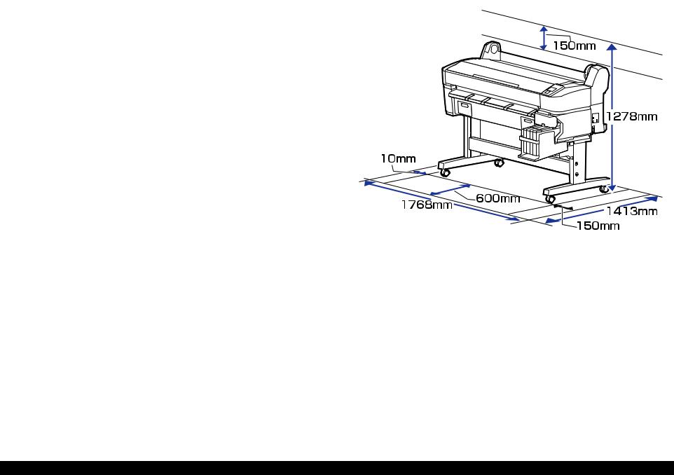
1.4.2 Installation Space |
This section provides the printer dimensions and shows the main components.
1.4.1 Dimensions and Weight
Table 1-8. Dimensions and Weight
Width |
Depth |
Height |
Weight* |
1608 mm |
917 mm |
1128 mm |
Approx. 90 kg |
|
|
|
|
Note "*": Ink not included.
Figure 1-1. Installation Space
PRODUCT DESCRIPTION |
Hardware Specifications |
16 |
Confidential

SC-F6000 series/SC-B6000 series |
|
Revision B |
|
1.4.3 Part Names |
|
Table 1-9. Front Side |
|
FRONT SIDE |
No. |
Name |
|
1 |
Printer cover |
||
|
|||
|
2 |
Maintenance box covers |
|
|
3 |
Casters |
|
|
4 |
Ink tank |
|
|
5 |
Slider |
|
|
6 |
Side cover |
|
|
7 |
AC inlet |
|
|
8 |
Option port |
|
|
9 |
LAN port |
|
|
10 |
Data light |
|
|
11 |
Status light |
|
|
12 |
USB port |
|
|
13 |
Control panel |
|
|
14 |
Alert lamp |
|
|
15 |
Roll rest |
|
|
16 |
Adapter guides |
|
|
17 |
Roll lock lever |
|
|
18 |
Adapter holder |
|
|
19 |
Paper slot |
|
|
20 |
Print head |
|
|
21 |
Paper eject guide |
Figure 1-2. Front Side
PRODUCT DESCRIPTION |
Hardware Specifications |
17 |
Confidential
SC-F6000 series/SC-B6000 series |
|
Revision B |
|
|
|
|
|
SLIDER |
|
ROLL PAPER ADAPTER |
|
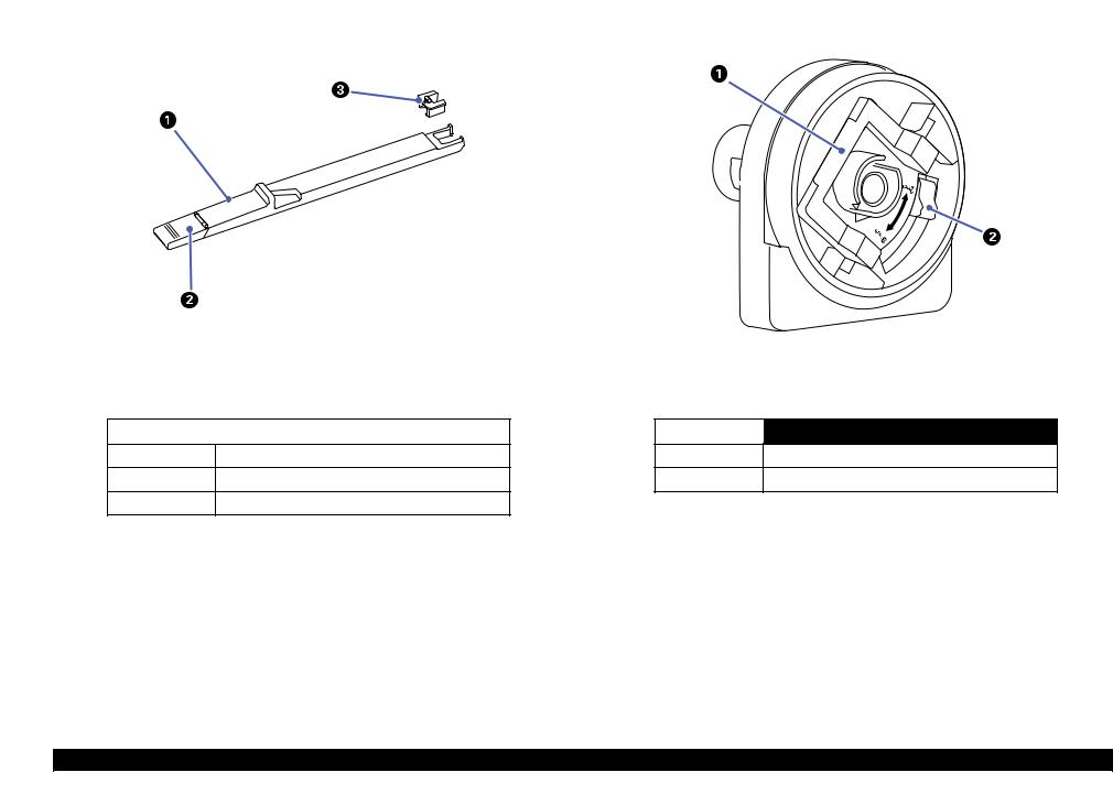
Figure 1-3. Slider
Table 1-10. Slider
No. |
Name |
|
|
1Slider
2Ink inlet cover
3Chip unit
Figure 1-4. Roll paper adapter
Table 1-11. Roll paper adapter
No. |
Name |
|
|
1Adapter lock lever
2Size lever
PRODUCT DESCRIPTION |
Hardware Specifications |
18 |
Confidential
SC-F6000 series/SC-B6000 series |
Revision B |
1.5 Control Panel Specifications
1.5.1 Control panel and LCD
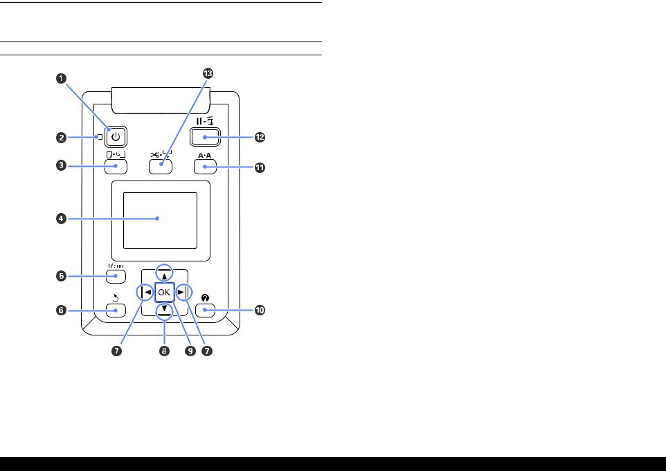
CONTROL PANEL
Figure 1-5. Control panel
|
Table 1-12. Control panel |
||
|
|
|
|
|
Name |
Function |
|
|
|
|
|
1 |
Power button |
Turns the power on and off. |
|
|
|
|
|
|
|
On: The power is on. |
|
2 |
Power light |
Flashing: The printer is receiving data or cleaning the |
|
print head or performing other operations in |
|||
|
|
the course of being shut down. |
|
|
|
Off: The power is off. |
|
|
|
|
|
3 |
Load/Remove Paper button |
Displays the Load/Remove Paper menu. |
|
|
|
|
|
4 |
Screen |
Displays the printer’s status, menus, error messages, and so |
|
on. |
|||
|
|
||
|
|
|
|
5 |
[Menu] button |
Displays the menu for the tab currently selected in the |
|
display. |
|||
|
|
||
|
|
|
|
6 |
Back button |
If menus are displayed, pressing this button takes you up |
|
one level in the menu hierarchy. |
|||
|
|
||
|
|
|
|
7 |
Left/Right buttons |
Use these buttons to select tabs. |
|
|
|
|
|
8 |
Up/Down buttons |
When menus are displayed, these buttons can be used to |
|
highlight items or options. |
|||
|
|
||
|
|
|
|
|
|
Displays the menu for the tab currently selected in the |
|
|
|
display. |
|
9 |
OK button |
When menus are displayed and an item is highlighted, |
|
pressing this button displays the sub-menu for the |
|||
|
|
highlighted item. |
|
|
|
If pressed while a parameter is selected from the Menu, |
|
|
|
the parameter is set or executed. |
|
|
|
|
|
10 |
Help button |
Displays the Help menu. |
|
|
|
|
|
11 |
Maintenance button |
Displays the Maintenance menu, which is used for nozzle |
|
checks and head cleaning. |
|||
|
|
||
|
|
|
|
|
|
The printer enters pause status if this is pressed while |
|
12 |
Pause/Cancel button |
printing. |
|
Pressing this button while a menu or help is displayed |
|||
|
|
closes the menu or help and returns the printer to ready |
|
|
|
status. |
|
|
|
|
|
|
|
It is used to manually cut roll paper using the built-in |
|
13 |
Feed/Cut Media button |
cutter. |
|
If printing is not currently in progress and the printer is |
|||
|
|
loaded with roll paper, you can feed paper ahead by |
|
|
|
pressing first this button and then the [T] button. |
|
|
|
|
|
PRODUCT DESCRIPTION |
Control Panel Specifications |
19 |
Confidential
SC-F6000 series/SC-B6000 series |
|
|
|
|
|
Revision B |
||||
|
|
|
|
|
|
|
|
Table 1-13. LCD |
||
LCD |
|
|
|
|
||||||
|
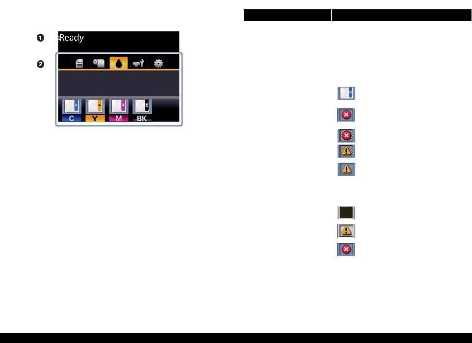
Screen View |
|
|
Name |
|
Function |
||||
|
|
|
|
|
|
|||||
|
|
|
|
|
|
1 |
Message |
Displays the printer’s status, operation, and error |
||
|
|
|
|
|
|
messages. |
||||
|
|
|
|
|
|
|
|
|
||
|
|
|
|
|
|
|
|
|
|
|
|
|
|
|
|
|
|
|
Displays print job status and can be used to access the |
||
|
|
|
|
|
|
|
|
Queues Tab |
Print Queues menu. |
|
|
|
|
|
|
|
|
|
|
|
|
|
|
|
|
|
|
|
|
Paper Tab |
Shows the type of paper in the printer and can be used to |
|
|
|
|
|
|
|
|
|
access the Paper menu. |
||
|
|
|
|
|
|
|
|
|
||
|
|
|
|
|
|
|
|
|
|
|
|
|
|
|
|
|
|
|
|
Displays the ink status of the chip unit. |
|
|
|
|
|
|
|
|
|
|
|
|
|
|
|
|
|
|
|
|
|
|
: No error. |
|
|
|
|
|
|
|
|
|
|
|
|
|
|
|
|
|
|
|
|
|
: An error occurred. |
|
|
|
|
|
|
|
|
Ink Tab |
|
|
|
|
|
|
Figure 1-6. LCD |
|
|
|
|
: The chip unit could not be recognized or it |
|
|
|
|
|
|
|
|
|
|
||
|
|
|
|
|
|
|
|
|
|
is not compatible with the printer. Or the |
|
|
|
|
|
|
2 |
Tabs/Info |
|
|
slider is not locked. |
|
|
|
|
|
|
Display Area |
|
|
|
|
|
|
|
|
|
|
|
|
|
|
|
|
|
|
|
|
|
|
|
|
|
: Ink is low. |
|
|
|
|
|
|
|
|
|
|
|
|
|
|
|
|
|
|
|
|
Shows the status of the Maintenance Box and is used to |
|
|
|
|
|
|
|
|
|
|
display the Maintenance menu. |
|
|
|
|
|
|
|
|
|
|
Maintenance Box status is shown as follows. |
|
|
|
|
|
|
|
|
|
|
|
|
|
|
|
|
|
|
|
|
Maintenance |
|
: No error. |
|
|
|
|
|
|
|
|
|
|
|
|
|
|
|
|
|
|
|
Tab |
|
: The Maintenance Box is nearing the end of |
|
|
|
|
|
|
|
|
|
||
|
|
|
|
|
|
|
|
|
|
|
|
|
|
|
|
|
|
|
|
|
its service life. |
|
|
|
|
|
|
|
|
|
|
: Maintenance Box is at the end of its service |
|
|
|
|
|
|
|
|
|
|
|
|
|
|
|
|
|
|
|
|
|
life. |
|
|
|
|
|
|
|
|
|
|
|
|
|
|
|
|
|
|
|
Setup Tab |
Displays the IP address and menus for various settings. |
|
|
|
|
|
|
|
|
|
|
|
|
PRODUCT DESCRIPTION |
Control Panel Specifications |
20 |
Confidential
SC-F6000 series/SC-B6000 series Revision B
1.5.2 Menu Descriptions
Table 1-14. Menu List
Menu |
Menu Item / Setting Value (Shaded one is the default) |
|
Explanation |
||
|
|
|
|
|
|
Print Queues menu |
Print Job Log Sheet |
|
|
Press the [OK] button to print the print job log. |
|
|
|
|
|
|
|
|
|
|
|
|
Press the [OK] button to view instructions for removing the paper. Follow the on- |
|
|
|
|
Remove Paper |
screen instructions to remove the paper. |
|
|
|
|
|
Instructions are not displayed if no paper is loaded. |
|
Load/Remove Paper |
|
|
|
|
|
|
|
|
After you make your selection, press the [OK] button. Follow the on-screen |
|
|
|
|
|
|
|
|
|
|
|
Roll Paper |
instructions to load the paper. |
|
|
|
|
If the roll paper is already loaded, the instructions for removing the loaded paper will |
|
|
|
|
|
|
|
|
|
|
|
|
be displayed before loading instructions are shown. |
|
|
|
|
|
|
|
|
RIP Settings |
Select the paper settings to use for printing. |
||
|
Select Paper Type |
|
|
If RIP Settings is selected, the paper settings set in the software RIP are used. |
|
|
|
|
|||
|
1 to 10 (Paper Settings Number) |
Set to a number between 1 and 10 to use the paper settings set in that slot for printing. To save a group of |
|||
|
|
||||
|
|
|
|
paper settings in this way, use Custom Paper Setting. |
|
|
|
|
|
|
|
Paper menu |
|
|
|
Photo Paper |
|
|
|
|
|
|
|
|
|
Select Reference |
Matte Paper |
You can select the media type that is the closest to the paper you are using. |
|
|
|
|
|||
|
|
|
|
||
|
|
|
Plain Paper |
||
|
|
|
Paper |
|
|
|
|
|
|
|
|
|
|
|
|
Others |
|
|
|
|
|
|
|
|
Custom Paper |
XXXXXXXXXXX |
|
No Paper Selected |
Select this option if you do not wish to specify the paper type. |
|
|
|
|
||
|
(name of custom |
|
Narrow |
|
|
|
Setting |
|
Select the platen gap which is the distance between the print head and the paper. |
||
|
paper type) |
|
|
||
|
|
|
Standard |
||
|
|
|
Platen Gap |
Normally, select “Standard”. Select a wider setting if printed images are smeared. If, |
|
|
|
|
Wide |
upon performing head alignment you feel that it is still not completely aligned, select |
|
|
|
|
|
||
|
|
|
|
|
“Narrow”. |
|
|
|
|
Wider |
|
|
|
|
|
|
|
|
|
|
|
|
|
|
|
|
Detect Paper |
Press the [OK] button to print a pattern to determine the thickness of the current paper. |
|
|
|
|
Thickness |
Select the pattern number with the least misalignment from the print results. |
|
|
|
|
|
|
|
PRODUCT DESCRIPTION |
Control Panel Specifications |
21 |
Confidential
|
SC-F6000 series/SC-B6000 series |
Revision B |
|
|
|
|
Table 1-14. Menu List |
|
|
|
|
|
Menu |
Menu Item / Setting Value (Shaded one is the default) |
Explanation |
|
|
|
|
Paper menu |
Custom Paper |
|
Setting |
||
|
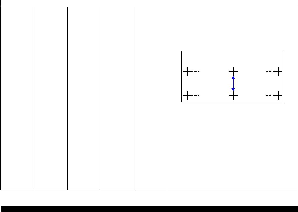
Pattern |
Use this setting if you are unable to resolve banding issues (horizontal striped lines or |
|
uneven colors) in the standard print area (for cut sheets, the area excluding the 1 to 2 |
|
|
|
cm strip at the bottom of the paper) even after head cleaning or head alignment. |
|
When “Pattern” is selected; |
|
Press the [OK] button to print an adjustment pattern. Measure the distances between |
|
the “+” symbols in the printed adjustment pattern. Use only the distance between the |
|
center symbols or the average of the distances between the left, center, and right |
|
symbols. |
Paper Feed Adjust
Value
XXXXXXXXXXX (name of custom paper type)
|
|
After the adjustment pattern is printing, the length of the pattern will be displayed in |
|
|
|
the control panel. Press the [S]/[T] buttons to enter the measured value and press |
|
|
|
the [OK] button. |
|
|
|
When “Value” is selected; |
|
|
|
Choose an adjustment between -0.70 and +0.70%. Selecting too small a value causes |
|
|
|
dark bands; adjust the amount upward. Similarly, choosing too large a value causes |
|
|
|
white bands; adjust the amount downward. |
|
|
|
|
|
|
|
It is important to choose the appropriate amount of suction for the paper used in order |
|
|
|
to maintain the correct distance between the paper and the print head. Choosing too |
|
Paper Suction |
-4 to 0 |
high a value for thin or soft paper will increase the distance between the paper and the |
|
print head, causing print quality to decline or preventing the paper feeding correctly. |
|||
|
|
||
|
|
If this happens, lower the paper suction. The suction power is weakened when the |
|
|
|
parameter is lowered. |
|
|
|
|
|
|
Normal |
|
|
|
|
|
|
Roll Paper Tension |
High |
Select “High” or “Extra High” if the paper wrinkles during printing. |
|
|
|
|
|
|
Extra High |
|
PRODUCT DESCRIPTION |
Control Panel Specifications |
22 |
Confidential

SC-F6000 series/SC-B6000 series |
|
|
|
|
|
Revision B |
|
|
|
|
|
Table 1-14. Menu List |
|
||
|
|
|
|
|
|
|
|
Menu |
Menu Item / Setting Value (Shaded one is the default) |
|
|
|
Explanation |
||
|
|
|
|
|
|
|
|
|
|
|
Remove Skew |
|
On |
|
Select whether to enable (“On”) or disable (“Off”) paper skew reduction. |
|
|
|
|
|
|
||
|
|
XXXXXXXXXXX |
|
Off |
|
||
|
|
|
|
|
|
||
|
Custom Paper |
|
|
|
|
|
|
|
Setting Name |
|
Enter a name of up to 22 characters for custom paper settings. Choose an easy-to-remember name for quick |
||||
|
(name of custom |
|
|||||
Paper menu |
Setting |
|
selection. |
|
|||
paper type) |
|
|
|
||||
|
|
|
Restore Settings |
|
Yes |
|
Restore the selected custom paper settings to default values. |
|
|
|
|
|
|
||
|
|
|
|
No |
|
||
|
|
|
|
|
|
|
|
|
|
|
|
|
|
|
|
|
Print Paper List |
|
|
|
Press the [OK] button to print a list of custom paper settings. |
||
|
|
|
|
|
|
||
|
Nozzle Check |
|
|
|
Press the [OK] button to print a nozzle check pattern. Visually inspect the printed pattern and perform head |
||
|
|
|
|
cleaning if you notice faint or missing areas. |
|||
|
|
|
|
|
|||
|
|
|
|
|
|
|
|
|
|
|
|
|
Execute (Light), |
|
Check the number of any patterns with faint or missing segments and specify whether |
|
|
All Nozzles |
|
|
Execute (Medium), |
|
you want to perform cleaning for all nozzles or only for the rows containing those |
|
|
|
|
|
Execute (Heavy) |
|
numbers. “All Nozzles” performs head cleaning for all nozzles. “Selected Nozzles” |
|
|
|
|
|
|
allows you to specify a row or rows of nozzles to perform head cleaning for. |
|
|
Head Cleaning |
|
|
|
|
|
|
|
|
|
|
|
|
||
|
|
|
|
Execute (Light), |
|
You can choose between the following levels for head cleaning: “Execute (Light), |
|
|
|
|
|
|
|
||
|
|
Selected Nozzles |
|
|
Execute (Medium), |
|
Execute (Medium)”, or “Execute (Heavy)”. At first, use “Execute (Light)”. If you |
Maintenance menu |
|
|
|
|
still notice any faint or missing areas, then use “Execute (Medium)”. If you still |
||
|
|
|
|
Execute (Heavy) |
|
||
|
|
|
|
|
|
notice any faint or missing areas, then use “Execute (Heavy)”. |
|
|
|
|
|
|
|
|
|
|
|
|
|
|
|
|
|
|
Head Alignment |
Manual(Uni-D) |
|
|
If print results are grainy or out of focus, perform head alignment to realign the print head. |
||
|
|
|
|
||||
|
Manual(Bi-D) |
|
|
||||
|
|
|
|
|
|
|
|
|
|
|
|
|
|
|
|
|
|
Adjust Cut Position |
|
|
-3 to 3 mm |
|
The cut position can be adjusted in increments of 0.1 mm. |
|
|
|
|
|
|
|
|
|
Cutter Maintenance |
|
|
|
Moves the cutter to the replacement position so it can be replaced. Press the [OK] button to move the cutter |
||
|
Replace Cutter |
|
|
to the replacement position. The paper must be removed before the cutter can be replaced. Remove the paper |
|||
|
|
|
|
||||
|
|
|
|
|
before proceeding. |
|
|
|
|
|
|
|
|
|
|
|
|
|
|
|
On |
|
Choose “On” to automatically cut roll paper using the built-in cutter as each page is |
|
|
|
Auto Cut |
|
|
|
printed, “Off” to disable auto paper cutting. However, borderless printing is not |
|
|
|
|
Off |
|
||
|
|
|
|
|
|
guaranteed on this printer. |
|
|
|
|
|
|
|
|
|
|
|
|
|
|
|
|
|
Setup menu |
Printer Setup |
Roll Paper Setup |
|
|
On |
|
If “On” is selected during borderless printing, the printer will automatically trim the |
Refresh Margin |
|
|
|
leading edge to remove any ink stains that may have been left by the previous copy; |
|||
|
Off |
|
|||||
|
|
|
|
|
|||
|
|
|
|
|
|
to disable this feature, choose “Off”. |
|
|
|
|
|
|
|
|
|
|
|
|
|
|
|
|
|
|
|
|
Page Line |
|
On |
|
If “Auto Cut” is “Off”, you can choose to print (“On”) or not print (“Off”) cut lines |
|
|
|
|
Off |
|
on roll paper. Cut lines are not printed if “Auto Cut” is “On”. |
|
|
|
|
|
|
|
||
|
|
|
|
|
|
|
|
PRODUCT DESCRIPTION |
Control Panel Specifications |
23 |
Confidential

SC-F6000 series/SC-B6000 series |
|
|
Revision B |
|||
|
|
|
Table 1-14. Menu List |
|
||
|
|
|
|
|
|
|
Menu |
Menu Item / Setting Value (Shaded one is the default) |
|
|
Explanation |
||
|
|
|
|
|
|
|
|
|
|
|
Normal |
|
|
|
|
|
|
|
|
|
|
|
|
|
Top 15 mm/ |
|
|
|
|
|
|
Bottom 15 mm |
|
|
|
|
|
|
|
|
|
|
|
|
|
Top 45 mm/ |
|
When set to “Normal”, the top and bottom margins are 15 mm, and the left and right |
|
|
|
Roll Paper Margin |
Bottom 15 mm |
|
margins are 3 mm. |
|
|
|
|
Top 15 mm/ |
|
Except for “15 mm”, the left and right margins for all other settings are 3 mm. |
|
|
|
|
Bottom 150 mm |
|
|
|
|
Roll Paper Setup |
|
|
|
|
|
|
|
3 mm |
|
|
|
|
|
|
|
|
|
|
|
|
|
|
15 mm |
|
|
|
|
|
|
|
|
|
|
|
|
Roll Paper |
On |
|
Select whether to display/record (On) or not to display/record (Off) the amount of |
|
|
|
|
|
remaining roll paper. “Roll Paper Remaining” can be enabled by selecting “On” and |
|
|
|
|
Remaining |
Off |
|
|
|
|
|
|
entering the length of the roll. |
||
|
|
|
|
|
|
|
|
|
|
|
|
|
|
|
|
|
|
1 to 15 m (4 to 50 |
|
Displayed when “On” is selected for “Roll Paper Remaining”. |
|
|
|
Remaining Alert |
|
Set within a range from 1 to 15 m (4 to 50 ft) to display a warning when the amount |
|
Setup menu |
Printer Setup |
|
ft) |
|
||
|
|
|
of remaining roll paper drops below that limit. You can set in 1 m (4 ft) increments. |
|||
|
|
|
|
|||
|
|
|
|
|
|
|
|
|
|
|
Low |
|
Select “High” or “Extra High” if the paper wrinkles during printing. |
|
|
|
|
|
|
“Roll Paper Tension” can be specified separately for each paper type using the |
|
|
|
|
Normal |
|
|
|
|
|
|
|
“Custom Paper Setting” option in the Paper menu. |
|
|
|
|
Roll Paper Tension |
|
|
|
|
|
|
High |
|
||
|
|
|
|
When “Custom Paper” is chosen for “Select Paper Type”, the printer will use the |
||
|
|
|
|
|
|
|
|
|
|
|
Extra High |
|
value selected for “Roll Paper Tension” in the “Custom Paper Setting”. |
|
|
|
|
|
This setting takes effect if no custom roll paper tension is specified. |
|
|
|
|
|
|
|
|
|
|
|
|
|
|
|
|
|
Advanced Settings |
|
On |
|
If the paper is thick, the print head may scuff the print surface. Choose “On” to |
|
|
Less Head Scuffing |
|
|
prevent scuffing. This option can be used to temporarily change the value selected for |
|
|
|
|
|
|||
|
|
|
|
|
||
|
|
|
Off |
|
“Custom Paper Setting” > “Platen Gap” in the Paper menu. Note, however, that “On” |
|
|
|
|
|
|
||
|
|
|
|
|
|
has no effect when “Wider” is selected for “Platen Gap”. |
|
|
|
|
|
|
Specify how long the printer pauses to allow the ink to dry after printing each page; |
|
|
|
Drying Time Per |
Off, 0.1 to 60 |
|
select Off or choose from values between 0.1 and 60 minutes. Depending on the ink |
|
|
|
|
density or paper type, the ink may take a while to dry. If the ink blurs on the paper, set |
||
|
|
|
Page |
minutes |
|
|
|
|
|
|
a longer time for drying the ink. |
||
|
|
|
|
|
|
|
|
|
|
|
|
|
The longer the drying time, the more time required for printing. |
|
|
|
|
|
|
|
PRODUCT DESCRIPTION |
Control Panel Specifications |
24 |
Confidential

SC-F6000 series/SC-B6000 series |
|
|
|
|
Revision B |
|
|
|
|
Table 1-14. Menu List |
|
||
|
|
|
|
|
|
|
Menu |
Menu Item / Setting Value (Shaded one is the default) |
Explanation |
||||
|
|
|
|
|
|
|
|
|
|
|
On |
|
Choose whether the printer automatically detects (“On”) or does not detect (“Off”) |
|
|
|
|
|
|
the paper width. Try choosing “Off” if a paper setting error is displayed when the |
|
|
|
|
|
|
|
|
|
|
Paper Size Check |
|
|
paper is correctly loaded. Note, however, that the printer may print outside the paper |
|
|
|
Off |
|
when “Off” is selected. If it prints beyond the edges of the paper, the inside of the |
|
|
|
|
|
|
||
|
|
|
|
|
|
printer becomes dirty with ink. We generally recommend to operate with this setting |
|
|
|
|
|
|
set to “On”. |
|
|
Advanced Settings |
|
|
|
|
|
|
|
On |
|
If “On” is selected, an error will be displayed in the control panel and printing will |
|
|
|
|
Paper Skew Check |
|
|
stop if the paper is skewed; select “Off” to disable this feature. “On” is recommended |
|
|
|
Off |
|
||
|
|
|
|
|
in most circumstances as skewed paper may cause the printer to jam. |
|
|
|
|
|
|
|
|
|
|
|
|
|
|
|
|
|
|
|
Off |
|
Select when to perform scheduled head cleaning; you can select from “Off” or after |
|
Printer Setup |
|
Cleaning Cycle |
|
|
every 1 to 10 pages. If “Off” is selected, no Cleaning Cycle is used. If you choose a |
|
|
|
|
|||
|
|
Every 1 to 10 pages |
|
number between 1 and 10 pages, head cleaning will be performed automatically |
||
|
|
|
|
|||
|
|
|
|
|
|
before printing occurs after the set number of pages is printed. |
|
|
|
|
|
|
|
|
|
Restore Settings |
|
Yes |
|
Select “Yes” to restore all printer settings to default values. |
|
|
|
|
|
||
Setup menu |
|
|
No |
|
||
|
|
|
|
|
||
|
|
|
|
|
|
|
|
|
Firmware Version |
|
xxxxxxx,x.xx,xxxx |
|
You can see the firmware version. |
|
|
|
|
|
|
|
|
|
Option Status |
|
Lists the optional accessories currently connected to the printer and available for use. |
||
|
|
|
|
|
|
|
|
|
Show Total Prints |
|
XXXXXXX m2 |
|
View the total area printed (six-figure maximum). |
|
|
|
(XXXXXX ft2) |
|
||
|
|
|
|
|
|
|
|
|
Print Status Sheet |
|
Press the [OK] button to print a list of current printer settings. |
||
|
|
|
Choose this option to view settings at a glance. |
|||
|
|
|
|
|||
|
|
|
|
|
|
|
|
|
|
|
Auto |
|
Select whether to use DHCP to set the IP address (“Auto”), or to set the address |
|
|
IP Address Setting |
|
|
|
manually (“Panel”). Choose “Panel” to enter the “IP address”, “Subnet Mask”, and |
|
|
|
Panel |
|
||
|
|
|
|
|
“Default Gateway”. |
|
|
|
|
|
|
|
|
|
|
|
|
|
|
|
|
Network Setup |
Print Status Sheet |
|
Press the [OK] button to print a list of network settings. Choose this option to view network settings at a |
||
|
|
|
glance. |
|
||
|
|
|
|
|
||
|
|
|
|
|
|
|
|
|
Restore Settings |
|
Yes |
|
Select “Yes” to restore all network settings to default values. |
|
|
|
|
|
||
|
|
|
No |
|
||
|
|
|
|
|
|
|
|
|
|
|
|
|
|
PRODUCT DESCRIPTION |
Control Panel Specifications |
25 |
Confidential

SC-F6000 series/SC-B6000 series |
|
|
|
Revision B |
||
|
|
|
Table 1-14. Menu List |
|
||
|
|
|
|
|
|
|
Menu |
Menu Item / Setting Value (Shaded one is the default) |
|
|
|
Explanation |
|
|
|
|
|
|
|
|
|
|
|
|
|
|
The printer enters sleep mode automatically when there are no errors, no print jobs |
|
|
Sleep Mode |
|
5 to 240 minutes |
|
being received, and no control panel or other operations are performed for the |
|
|
|
|
selected period. Use this option to choose the period before the printer enters sleep |
||
|
|
|
|
|
|
|
|
|
|
|
|
|
mode. |
|
|
|
|
|
|
|
|
|
|
|
Off |
|
The printer turns off automatically when there are no errors, no print jobs being |
|
Power Settings |
|
|
|
|
received, and no control panel or other operations are performed for eight hours. |
|
|
|
|
|
||
|
Power Off Timer |
|
|
|
The delay before the printer turns off can be selected from values between 1 and 24 |
|
|
|
|
1 to 24 hours |
|
||
|
|
|
|
|
hours in increments of 1 hour. |
|
|
|
|
|
|
|
|
|
|
|
|
|
|
Choose “Off” to prevent the printer turning off automatically. |
|
|
|
|
|
|
|
|
|
Restore Settings |
|
Yes |
|
Select “Yes” to restore all “Power Settings” to default values. |
|
|
|
|
|
||
|
|
|
No |
|
||
|
|
|
|
|
|
|
|
|
|
|
|
|
|
|
|
|
|
Japanese |
|
|
|
|
|
|
|
|
|
|
|
|
|
English |
|
|
|
|
|
|
|
|
|
Setup menu |
|
|
|
French |
|
|
|
|
|
|
|
|
|
|
|
|
Italian |
|
|
|
|
|
|
|
|
|
|
|
|
|
|
|
|
|
|
|
|
|
German |
|
|
|
|
|
|
|
|
|
|
|
Language |
|
Portuguese |
|
Select the language used on the control panel’s screen. |
|
|
|
|
|
|
|
|
|
|
|
Spanish |
|
|
|
|
|
|
|
|
|
|
Preference |
|
|
Dutch |
|
|
|
|
|
|
|
|
|
|
|
|
|
Russian |
|
|
|
|
|
|
|
|
|
|
|
|
|
Korean |
|
|
|
|
|
|
|
|
|
|
|
|
|
Chinese |
|
|
|
|
|
|
|
|
|
|
|
Unit: Length |
|
m |
|
Select the unit of length which is displayed on the control panel’s screen or printed on |
|
|
|
ft/in |
|
the patterns. |
|
|
|
|
|
|
||
|
|
|
|
|
|
|
|
|
Alert Lamp Setting |
|
On |
|
Choose whether the large alert lamp lights (“On”) or does not light (“Off”) when an |
|
|
|
Off |
|
error occurs. |
|
|
|
|
|
|
||
|
|
|
|
|
|
|
PRODUCT DESCRIPTION |
Control Panel Specifications |
26 |
Confidential

SC-F6000 series/SC-B6000 series |
|
|
|
|
Revision B |
|
|
|
|
Table 1-14. Menu List |
|
||
|
|
|
|
|
|
|
Menu |
Menu Item / Setting Value (Shaded one is the default) |
|
|
|
Explanation |
|
|
|
|
|
|
|
|
|
|
Date And Time |
|
MM/DD/YY |
|
Set the printer’s built-in clock. The printer clock provides the times that appear in |
|
|
|
HH:MM |
|
print outs of job information and printer status. |
|
|
|
|
|
|
||
|
|
|
|
|
|
|
Setup menu |
Administrator |
Time Zone |
|
Enter the difference between the current time zone and GMT. |
||
|
The selected time zone is used in e-mail notifications sent by Remote Manager when an error occurs. |
|||||
Menu |
|
|||||
|
|
|
||||
|
|
|
|
|
|
|
|
|
Reset All Settings |
|
Yes |
|
Select “Yes” to restore defaults for all settings except the “Date And Time”, |
|
|
|
No |
|
“Language”, and “Unit: Length” options in the Setup menu. |
|
|
|
|
|
|
||
|
|
|
|
|
|
|
PRODUCT DESCRIPTION |
Control Panel Specifications |
27 |
Confidential

SC-F6000 series/SC-B6000 series |
Revision B |
1.5.3 Serviceman Mode
The Serviceman Mode is intended to be used by a service person for servicing the printer.
HOW TO START & QUIT
1.Turn the printer on by pressing the [Menu], [Back], and [OK] buttons together.
2.Turn the printer off to quit the Serviceman Mode.
SERVICEMAN MODE MENU LIST
|
|
Menu |
|
Explanation |
|
Class |
1 |
2 |
3 |
||
|
|||||
|
|
|
|
|
|
|
Paper |
|
|
Adjusts the detection accuracy of the PAPER THICKNESS SENSOR. |
|
|
|
|
|
|
|
|
Rear AD |
|
|
Adjusts the AD value of the PE Sensor. |
|
|
|
|
|
|
|
|
CR Un Cap |
|
|
Unlocks or re-locks the carriage and uncaps/re-caps the Print Head. |
|
|
|
|
|
|
|
Mecha Adjustment |
|
Red |
|
|
|
|
|
|
|
||
LCD RGB Check |
Green |
|
Checks the operation of the LCD. |
||
|
|
||||
|
|
|
|
|
|
|
|
Blue |
|
|
|
|
|
|
|
|
|
|
Panel Check |
|
|
Checks the operation of the buttons and the LEDs. |
|
|
|
|
|
|
|
|
Sensor Check |
ILS |
|
Checks the operation of sensors. |
|
|
|
|
|
|
PRODUCT DESCRIPTION |
Control Panel Specifications |
28 |
Confidential

SC-F6000 series/SC-B6000 series |
|
|
Revision B |
|
|
|
|
|
|
|
|
|
|
Menu |
|
Explanation |
|
Class |
1 |
2 |
3 |
|
|
|
|
||||
|
|
|
|
|
|
|
|
|
PG-- |
|
|
|
|
|
|
|
|
|
|
|
PG- |
|
|
|
|
|
|
|
|
|
|
PG |
PGtyp |
|
|
|
|
|
|
|
|
|
|
|
PG+ |
|
|
|
|
|
|
|
|
|
|
|
PG++ |
|
|
|
|
|
|
|
|
|
|
|
400 CPS |
|
|
|
|
|
|
|
|
Life |
CR |
H to F Speed |
500 CPS |
Used only in manufacturing processes. Not used in service operations. |
|
|
|
|
|||
|
240 CPS |
|
|||
|
|
|
|
|
|
|
|
|
|
|
|
|
|
|
400 CPS |
|
|
|
|
|
|
|
|
|
|
F to H Speed |
500 CPS |
|
|
|
|
|
|
|
|
|
|
|
240 CPS |
|
|
|
|
|
|
|
|
|
|
Page Size |
|
|
|
|
|
|
|
|
|
|
|
Fan |
|
|
|
|
|
|
|
|
|
|
|
Life Count |
|
|
|
|
|
|
|
|
|
PRODUCT DESCRIPTION |
Control Panel Specifications |
29 |
Confidential

SC-F6000 series/SC-B6000 series |
|
|
|
Revision B |
|
|
|
|
|
|
|
|
|
|
|
Menu |
|
|
Explanation |
|
Class |
1 |
2 |
3 |
|
|
|
|
|
|
||||
|
|
|
|
|
|
|
|
|
Feed Amount 1 |
|
|
|
|
|
|
|
|
|
|
|
|
|
|
PS1 |
|
|
|
|
|
|
|
|
|
|
|
|
Feed Speed 1 |
PS2 |
|
|
|
|
|
|
|
|
|
|
|
|
PS3 |
|
|
|
|
|
|
|
|
|
|
|
|
|
|
|
|
|
|
|
|
|
PS4 |
|
|
|
|
|
|
|
|
|
|
|
|
Feed Amount 2 |
|
|
|
|
|
|
|
|
|
|
|
|
PF |
|
PS1 |
|
|
|
|
|
|
|
|
|
|
|
|
Feed Speed 2 |
PS2 |
|
|
|
|
|
|
|
|
|
|
|
|
PS3 |
|
|
|
|
|
|
|
|
|
|
|
|
|
|
|
|
|
|
|
|
|
PS4 |
|
|
|
|
|
|
|
|
|
|
|
|
Wait |
|
|
|
|
|
|
|
|
|
|
|
|
|
Fan |
|
|
|
|
|
|
|
|
|
|
|
|
|
Life Count |
|
|
|
|
|
|
|
|
|
|
|
Life |
|
Wait1 |
|
|
Used only in manufacturing processes. Not used in service operations. |
|
|
|
|
|
|
||
RLS |
Wait2 |
|
|
|
||
|
|
|
|
|
||
|
|
|
|
|
|
|
|
|
Life Count |
|
|
|
|
|
|
|
|
|
|
|
|
|
|
PG-- |
|
|
|
|
|
|
|
|
|
|
|
|
|
PG- |
|
|
|
|
|
|
|
|
|
|
|
|
PG |
PGtyp |
|
|
|
|
|
|
|
|
|
|
|
APG |
|
PG+ |
|
|
|
|
|
|
|
|
|
|
|
|
|
PG++ |
|
|
|
|
|
|
|
|
|
|
|
|
Wait |
|
|
|
|
|
|
|
|
|
|
|
|
|
Life Count |
|
|
|
|
|
|
|
|
|
|
|
|
|
Length |
|
|
|
|
|
|
|
|
|
|
|
|
Cutter |
Return Length |
|
|
|
|
|
|
|
|
|
|
|
|
Wait |
|
|
|
|
|
|
|
|
|
|
|
|
|
|
|
|
|
|
|
|
|
Life Count |
|
|
|
|
|
|
|
|
|
|
|
|
Display Count |
|
|
|
|
|
|
|
|
|
|
|
|
|
|
|
|
|
|
|
PRODUCT DESCRIPTION |
|
Control Panel Specifications |
30 |
|
||
Confidential
Loading...