


 Loading...
Stylus Pro 4880 Field Repair Guide |
1/17/08 |
|
|
Table Of Contents
Table Of Contents - - - - - - - - - - - - - |
- |
|
- |
- |
- |
|
- |
- |
- |
|
- |
- |
- |
|
- |
- |
- |
|
- |
- |
- |
|
- |
1 |
|||||||||||||
Control Panel Map - - - |
- |
|
- |
- |
- |
|
- |
- |
|
- |
|
- |
- |
- |
|
- |
- |
- |
|
- |
- |
- |
|
- |
- |
- |
|
- |
- |
- |
|
- |
- |
- |
|
- |
5 |
Component Replacement |
- |
|
- |
- |
- |
|
- |
- |
|
- |
|
- |
- |
- |
|
- |
- |
- |
|
- |
- |
- |
|
- |
- |
- |
|
- |
- |
- |
|
- |
- |
- |
|
- 12 |
|
Board (Main) Installation - |
- |
|
- |
- |
- |
- |
- |
- |
- |
- |
- |
- |
- |
- |
- |
- |
- |
- |
- |
- |
- |
- |
- |
- |
- |
- |
- |
- |
- |
13 |
|||||||
Board (Main) Removal |
- |
- |
- |
- - |
- |
- |
- |
- |
- |
- |
- |
- |
- |
- |
- |
- |
- |
- |
- |
- |
- |
- |
- |
- |
- |
- |
- |
- |
- |
20 |
|||||||
Board (Power Supply) Removal |
- |
- |
- |
- |
- |
- |
- |
- |
- |
- |
- |
- |
- |
- |
- |
- |
- |
- |
- |
- |
- |
- |
- |
- |
- |
27 |
|||||||||||
Carriage Removal Procedure |
|
- |
- |
- |
- |
- |
- |
- |
- |
- |
- |
- |
- |
- |
- |
- |
- |
- |
- |
- |
- |
- |
- |
- |
- |
- |
- |
33 |
|||||||||
Cartridge Release Lever Repair |
- |
- |
- |
- |
- |
- |
- |
- |
- |
- |
- |
- |
- |
- |
- |
- |
- |
- |
- |
- |
- |
- |
- |
- |
- |
36 |
|||||||||||
Cartridge Release Sensor Repair |
- |
- |
- |
- |
- |
- |
- |
- |
- |
- |
- |
- |
- |
- |
- |
- |
- |
- |
- |
- |
- |
- |
- |
- |
37 |
||||||||||||
Cover (Left) Removal |
|
- |
- |
- |
|
- |
- |
- |
- |
- |
- |
- |
- |
- |
- |
- |
- |
- |
- |
- |
- |
- |
- |
- |
- |
- |
- |
- |
- |
- |
- |
- |
38 |
||||
Cover (Right) Removal |
- |
- |
- |
|
- |
- |
- |
- |
- |
- |
- |
- |
- |
- |
- |
- |
- |
- |
- |
- |
- |
- |
- |
- |
- |
- |
- |
- |
- |
- |
- |
40 |
|||||
Cover (Top) Removal |
|
- |
- |
- |
|
- |
- |
- |
- |
- |
- |
- |
- |
- |
- |
- |
- |
- |
- |
- |
- |
- |
- |
- |
- |
- |
- |
- |
- |
- |
- |
- |
45 |
||||
Damper Removal |
- |
- |
- |
- |
- |
|
- |
- |
- |
- |
- |
- |
- |
- |
- |
- |
- |
- |
- |
- |
- |
- |
- |
- |
- |
- |
- |
- |
- |
- |
- |
- |
- |
46 |
|||
Ink Bay Removal (Left) - |
- |
- |
|
- |
- |
- |
- |
- |
- |
- |
- |
- |
- |
- |
- |
- |
- |
- |
- |
- |
- |
- |
- |
- |
- |
- |
- |
- |
- |
- |
54 |
||||||
Ink Bay Removal (Right) - |
- |
|
- |
- |
- |
- |
- |
- |
- |
- |
- |
- |
- |
- |
- |
- |
- |
- |
- |
- |
- |
- |
- |
- |
- |
- |
- |
- |
- |
59 |
|||||||
Input Roller Assembly, Disassembly |
|
- |
- |
- |
- |
- |
- |
- |
- |
- |
- |
- |
- |
- |
- |
- |
- |
- |
- |
- |
- |
- |
- |
64 |
|||||||||||||
Input Roller Assembly, Re-assembly |
|
- |
- |
- |
- |
- |
- |
- |
- |
- |
- |
- |
- |
- |
- |
- |
- |
- |
- |
- |
- |
- |
- |
69 |
|||||||||||||
Input Roller Assembly Removal |
- |
- |
- |
- |
- |
- |
- |
- |
- |
- |
- |
- |
- |
- |
- |
- |
- |
- |
- |
- |
- |
- |
- |
- |
- |
74 |
|||||||||||
Paper Exit Roller Removal |
- |
|
- |
- |
- |
- |
- |
- |
- |
- |
- |
- |
- |
- |
- |
- |
- |
- |
- |
- |
- |
- |
- |
- |
- |
- |
- |
- |
- |
79 |
|||||||
Print Head Replacement Procedure |
- |
- |
- |
- |
- |
- |
- |
- |
- |
- |
- |
- |
- |
- |
- |
- |
- |
- |
- |
- |
- |
- |
- |
82 |
|||||||||||||
Pump and Cap Installation - |
|
- |
- |
- |
- |
- |
- |
- |
- |
- |
- |
- |
- |
- |
- |
- |
- |
- |
- |
- |
- |
- |
- |
- |
- |
- |
- |
- |
89 |
||||||||
Pump and Cap Removal - |
- |
- - |
- |
- |
- |
- |
- |
- |
- |
- |
- |
- |
- |
- |
- |
- |
- |
- |
- |
- |
- |
- |
- |
- |
- |
- |
- |
95 |
|||||||||
Troubleshooting - - - - - - - - - - - - - |
- |
- |
|
- |
- |
- |
|
- |
- |
- |
|
- |
- |
- |
|
- |
- |
- |
|
- |
- |
- |
|
100 |
|||||||||||||
Error Codes (Maintenance) |
|
|
- |
- |
- |
- |
- |
- |
- |
- |
- |
- |
- |
- |
- |
- |
- |
- |
- |
- |
- |
- |
- |
- |
- |
- |
- |
- |
- 101 |
||||||||
Error Codes (Service) |
- |
- |
- |
|
- |
- |
- |
- |
- |
- |
- |
- |
- |
- |
- |
- |
- |
- |
- |
- |
- |
- |
- |
- |
- |
- |
- |
- |
- |
- |
- 102 |
||||||
00000088 - - - - - - - |
- - |
- |
- - |
- |
- |
- |
- |
- |
- |
- |
- |
- |
- |
- |
- |
- |
- |
- |
- |
- |
- |
- |
- |
- |
- |
- |
- |
- 105 |
|||||||||
00000101 - - - - - - - |
- - |
- |
- - |
- |
- |
- |
- |
- |
- |
- |
- |
- |
- |
- |
- |
- |
- |
- |
- |
- |
- |
- |
- |
- |
- |
- |
- |
- 106 |
|||||||||
00000103 - - - - - - - |
- - |
- |
- - |
- |
- |
- |
- |
- |
- |
- |
- |
- |
- |
- |
- |
- |
- |
- |
- |
- |
- |
- |
- |
- |
- |
- |
- |
- 107 |
|||||||||
00000105 - - - - - - - |
- - |
- |
- - |
- |
- |
- |
- |
- |
- |
- |
- |
- |
- |
- |
- |
- |
- |
- |
- |
- |
- |
- |
- |
- |
- |
- |
- |
- 108 |
|||||||||
00010000 - 00010003 - - - |
- |
- - |
- |
- |
- |
- |
- |
- |
- |
- |
- |
- |
- |
- |
- |
- |
- |
- |
- |
- |
- |
- |
- |
- |
- |
- |
- 109 |
||||||||||
0001001B - |
- |
- |
- |
- |
- |
- - |
- |
- - |
- - |
- |
- |
- |
- |
- |
- |
- |
- |
- |
- |
- |
- |
- |
- |
- |
- |
- |
- |
- |
- |
- |
- |
- 110 |
|||||
Color Shift - |
- |
- |
- |
- |
- |
- |
- |
- |
|
- |
- |
- |
- |
- |
- |
- |
- |
- |
- |
- |
- |
- |
- |
- |
- |
- |
- |
- |
- |
- |
- |
- |
- |
- |
- |
- 111 |
|
Command Error |
- |
- |
- |
- |
- |
- |
|
- |
- |
- |
- |
- |
- |
- |
- |
- |
- |
- |
- |
- |
- |
- |
- |
- |
- |
- |
- |
- |
- |
- |
- |
- |
- |
- 112 |
|||
Printer Component, Software Item, LCD Display, Printer Button |
Page 1. |
Stylus Pro 4880 Field Repair Guide |
|
|
|
|
|
|
|
|
|
|
|
|
|
|
|
|
|
|
|
|
|
|
|
|
|
|
|
|
|
|
|
|
|
|
|
|
|
|
|
1/17/08 |
||
|
|
|
|
|
|
|
|
|
|
|
|
|
|
|
|
|
|
|
|
|
|
|
|
|
|
|
|
|
|
|||||||||||||
Communication Errors PC - |
- |
|
- |
- |
|
- |
- |
- |
- - |
- |
- |
- |
- |
- |
|
- |
- |
- |
- |
- |
- |
- |
- |
- |
- |
- |
- |
- |
- 113 |
|||||||||||||
Cover Open |
|
- |
- |
- |
- |
- |
|
- |
- |
- |
- |
|
- |
- |
|
- |
- |
|
- |
- |
- |
- |
- |
- |
- |
- |
|
- |
- |
- |
- |
- |
- |
- |
- |
- |
- |
- |
- |
- |
- 115 |
|
Drop of Ink |
- |
- |
- |
- |
- |
- |
- |
- |
- |
- |
- |
- |
- |
- |
|
- |
- |
- |
- |
- |
- |
- |
- |
|
- |
- |
- |
- |
- |
- |
- |
- |
- |
- |
- |
- |
- |
- 116 |
||||
Grainy or Ghosting |
|
- |
|
- |
- |
- |
- |
|
- |
- |
|
- |
- |
|
- |
- |
- |
- |
- |
- |
- |
- |
|
- |
- |
- |
- |
- |
- |
- |
- |
- |
- |
- |
- |
- |
- 117 |
|||||
Horizontal Banding |
|
- |
|
- |
- |
- |
- |
|
- |
- |
|
- |
- |
|
- |
- |
- |
- |
- |
- |
- |
- |
|
- |
- |
- |
- |
- |
- |
- |
- |
- |
- |
- |
- |
- |
- 118 |
|||||
Missing Nozzle Diagnosis and Repair |
|
- |
- |
- |
- |
- |
- |
- |
- |
|
- |
- |
- |
- |
- |
- |
- |
- |
- |
- |
- |
- |
- |
- 120 |
||||||||||||||||||
Paper Jam Errors |
- |
- |
|
- |
- |
- |
- |
|
- |
- |
|
- |
- |
|
- |
- |
- |
- |
- |
- |
- |
- |
|
- |
- |
- |
- |
- |
- |
- |
- |
- |
- |
- |
- |
- |
- 123 |
|||||
Paper Not Cut |
|
- |
- |
- |
- |
|
- |
- |
- |
- |
|
- |
- |
|
- |
- |
|
- |
- |
- |
- |
- |
- |
- |
- |
|
- |
- |
- |
- |
- |
- |
- |
- |
- |
- |
- |
- |
- |
- 124 |
||
Reload Paper |
|
- |
- |
- |
- |
|
- |
- |
- |
- |
|
- |
- |
|
- |
- |
|
- |
- |
- |
- |
- |
- |
- |
- |
|
- |
- |
- |
- |
- |
- |
- |
- |
- |
- |
- |
- |
- |
- 125 |
||
Random Nozzles - |
- |
- |
- |
- |
- |
- |
- |
- |
- |
- |
- |
- |
- |
- |
- |
- |
- |
- |
|
- |
- |
- |
- |
- |
- |
- |
- |
- |
- |
- |
- |
- |
- 127 |
|||||||||
Scratch - - - - - - - |
- |
- |
- |
- |
- |
|
- |
- |
|
- |
- |
|
- |
- |
- |
- |
- |
- |
- |
- |
|
- |
- |
- |
- |
- |
- |
- |
- |
- |
- |
- |
- |
- |
- 128 |
|||||||
Set Ink Cartridges |
- |
- |
|
- |
- |
- |
- |
|
- |
- |
|
- |
- |
|
- |
- |
- |
- |
- |
- |
- |
- |
|
- |
- |
- |
- |
- |
- |
- |
- |
- |
- |
- |
- |
- |
- 129 |
|||||
Set Ink Lever |
- |
- |
- |
- |
- |
- |
- |
- |
- |
- |
- |
- |
- |
|
- |
- |
- |
- |
- |
- |
- |
- |
|
- |
- |
- |
- |
- |
- |
- |
- |
- |
- |
- |
- |
- |
- 130 |
|||||
Smear |
- - |
- |
- |
- |
- |
- |
- |
|
- |
- |
- |
- |
|
- |
- |
|
- |
- |
|
- |
- |
- |
- |
- |
- |
- |
- |
|
- |
- |
- |
- |
- |
- |
- |
- |
- |
- |
- |
- |
- |
- 131 |
Smudge |
- |
- |
- |
- |
- |
- |
- |
|
- |
- |
- |
- |
|
- |
- |
|
- |
- |
|
- |
- |
- |
- |
- |
- |
- |
- |
|
- |
- |
- |
- |
- |
- |
- |
- |
- |
- |
- |
- |
- |
- 132 |
Vertical Banding |
- |
- |
- |
- |
- |
- |
- |
- |
- |
- |
- |
- |
- |
- |
- |
- |
- |
- |
- |
|
- |
- |
- |
- |
- |
- |
- |
- |
- |
- |
- |
- |
- |
- 133 |
||||||||
Wrong Ink Cartridge |
- |
|
- |
- |
- |
- |
|
- |
- |
|
- |
- |
|
- |
- |
- |
- |
- |
- - |
- |
- - |
- |
- |
- |
- |
- |
- |
- |
- |
- |
- |
- |
- 134 |
|||||||||
Adjustments - - - - |
- |
- |
- |
|
- |
- |
- |
|
|
- |
- |
- |
|
|
- |
|
- |
- |
|
- |
- |
- |
|
- |
- |
- |
|
- |
- |
- |
|
- |
- |
- |
|
- |
- |
- |
|
135 |
||
980mm Feed Adjustment |
- |
- |
|
- |
- |
|
- |
- |
|
- |
- |
- |
- |
- |
- |
- |
- |
|
- |
- |
- |
- |
- |
- |
- |
- |
- |
- |
- |
- |
- |
- 136 |
||||||||||
Auto Bi-D Adjustment |
|
- |
- |
- |
- |
|
- |
- |
|
- |
- |
|
- |
- |
- |
- |
- |
- |
- |
- |
|
- |
- |
- |
- |
- |
- |
- |
- |
- |
- |
- |
- |
- |
- 137 |
|||||||
Auto Uni-D Adjustment |
|
- |
- |
- |
|
- |
- |
|
- |
- |
|
- |
- |
- |
- |
- |
- |
- |
- |
|
- |
- |
- |
- |
- |
- |
- |
- |
- |
- |
- |
- |
- |
- 138 |
||||||||
Carriage Timing Belt Tension Adjustment - |
- |
- |
- |
- |
- |
|
- |
- |
- |
- |
- |
- |
- |
- |
- |
- |
- |
- |
- |
- 139 |
||||||||||||||||||||||
Check Network Communication |
- |
|
- |
- |
|
- |
- - |
- |
- |
- - |
- |
- - |
- |
- |
- |
- |
- |
- |
- |
- |
- |
- |
- |
- 140 |
||||||||||||||||||
Check Nozzle |
|
- |
- |
- |
- |
|
- |
- |
- |
- |
|
- |
- |
|
- |
- |
|
- |
- |
- |
- |
- |
- |
- |
- |
|
- |
- |
- |
- |
- |
- |
- |
- |
- |
- |
- |
- |
- |
- 142 |
||
Check Platen Gap |
- |
- |
|
- |
- |
- |
- |
|
- |
- |
|
- |
- |
|
- |
- |
- |
- |
- |
- |
- |
- |
|
- |
- |
- |
- |
- |
- |
- |
- |
- |
- |
- |
- |
- |
- 143 |
|||||
Cleaning / Charging (Priming) |
|
- |
- |
|
- |
- |
|
- |
- |
- |
- |
- |
- |
- |
- |
|
- |
- |
- |
- |
- |
- |
- |
- |
- |
- |
- |
- |
- |
- 144 |
||||||||||||
Clear PF Micro Feed Adjustment [Bi-D] |
- |
- |
- |
- |
- |
- |
- |
|
- |
- |
- |
- |
- |
- |
- |
- |
- |
- |
- |
- |
- |
- 145 |
||||||||||||||||||||
Copy Bi-D Variables |
- |
|
- |
- |
- |
- |
|
- |
- |
|
- |
- |
|
- |
- |
- |
- |
- |
- |
- |
- |
|
- |
- |
- |
- |
- |
- |
- |
- |
- |
- |
- |
- |
- |
- 146 |
||||||
Copy Uni-D Variables |
|
|
- |
- |
- |
- |
|
- |
- |
|
- |
- |
|
- |
- |
- |
- |
- |
- |
- |
- |
|
- |
- |
- |
- |
- |
- |
- |
- |
- |
- |
- |
- |
- |
- 147 |
||||||
CR Encoder Sensor Position Adjustment |
- |
- |
- |
- |
- |
- |
|
- |
- |
- |
- |
- |
- |
- |
- |
- |
- |
- |
- |
- |
- 148 |
|||||||||||||||||||||
Head Rank ID |
|
- |
- |
- |
- |
|
- |
- |
- |
- |
|
- |
- |
|
- |
- |
|
- |
- |
- |
- |
- |
- |
- |
- |
|
- |
- |
- |
- |
- |
- |
- |
- |
- |
- |
- |
- |
- |
- 149 |
||
Ink Discharge. |
- |
- |
- |
- |
|
- |
- |
- |
- |
|
- |
- |
|
- |
- |
|
- |
- |
- |
- |
- |
- |
- |
- |
|
- |
- |
- |
- |
- |
- |
- |
- |
- |
- |
- |
- |
- |
- 150 |
|||
Multi Sensor Adjustment |
- |
- |
|
- |
- |
|
- |
- |
|
- |
- |
- |
- |
- |
- |
- |
- |
|
- |
- |
- |
- |
- |
- |
- |
- |
- |
- |
- |
- |
- |
- 151 |
||||||||||
Multi Sensor Auto PF Adjustment |
- |
- |
|
- |
- |
- |
- |
- |
- |
- |
- |
|
- |
- |
- |
- |
- |
- |
- |
- |
- |
- |
- |
- |
- |
- 152 |
||||||||||||||||
Multi Sensor Level Adjustment |
|
- |
|
- |
- |
|
- |
- |
- |
- |
- |
- |
- |
- |
|
- |
- |
- |
- |
- |
- |
- |
- |
- |
- |
- |
- |
- |
- 153 |
|||||||||||||
Multi Sensor Position Adjustment - |
- |
|
- |
- |
- |
- |
- |
- - |
- |
- - |
- |
- |
- |
- |
- |
- |
- |
- |
- |
- |
- |
- 154 |
||||||||||||||||||||
Nozzle Bi-D Adjustment |
- |
- |
- |
|
- |
- |
|
- |
- |
|
- |
- |
- |
- |
- |
- |
- |
- |
|
- |
- |
- |
- |
- |
- |
- |
- |
- |
- |
- |
- |
- |
- 156 |
|||||||||
Printer Component, Software Item, LCD Display, Printer Button |
Page 2. |
Stylus Pro 4880 Field Repair Guide |
|
|
|
|
|
|
|
|
|
|
|
|
|
|
|
|
|
|
|
|
|
|
|
|
|
|
|
|
|
|
|
1/17/08 |
|
|
|
|
|
|
|
|
|
|
|
|
|
|
|
|
|
|
|
|
|
|
|
|
|||||||||||
Paper Feed Timing Belt Adjustment - |
- |
- |
- |
- |
- |
- |
- |
- |
- |
- |
- |
- |
- |
- |
- |
- |
- |
- |
- |
- |
- |
- 157 |
|||||||||||
Paper Thickness Sensor Adjustment |
- |
- |
- |
- |
- |
- |
- |
- |
- |
- |
- |
- |
- |
- |
- |
- |
- |
- |
- |
- |
- |
- 159 |
|||||||||||
Platen Gap Adjustment |
|
- |
- |
- |
- |
- |
- |
- |
- |
- |
- |
- |
- |
- |
- |
- |
- |
- |
- |
- |
- |
- |
- |
- |
- |
- |
- |
- |
- |
- 162 |
|||
Platen Position Adjustment |
- |
- |
- |
- |
- |
- |
- |
- |
- |
- |
- |
- |
- |
- |
- |
- |
- |
- |
- |
- |
- |
- |
- |
- |
- |
- |
- 165 |
||||||
Print Head Slant Adjustment |
(CR) |
- |
- |
- |
- |
- |
- |
- |
- |
- |
- |
- |
- |
- |
- |
- |
- |
- |
- |
- |
- |
- |
- |
- |
- 167 |
||||||||
Print Head Slant Adjustment |
(PF) |
- |
- |
- |
- |
- |
- |
- |
- |
- |
- |
- |
- |
- |
- |
- |
- |
- |
- |
- |
- |
- |
- |
- |
- 174 |
||||||||
Rear Sensor Calibration |
- |
- |
- |
- |
- |
- |
- |
- |
- |
- |
- |
- |
- |
- |
- |
- |
- |
- |
- |
- |
- |
- |
- |
- |
- |
- |
- |
- |
- 176 |
||||
Reset ASF Counter |
|
- |
- |
- |
- |
- |
- |
- |
- |
- |
- |
- |
- |
- |
- |
- |
- |
- |
- |
- |
- |
- |
- |
- |
- |
- |
- |
- |
- |
- |
- |
- 177 |
|
Reset Paper Ejection Switching / PG Switching Counter |
- |
- |
- |
- |
- |
- |
- |
- |
- |
- |
- |
- 178 |
|||||||||||||||||||||
Reset PF Motor Counter |
- |
- |
- |
- |
- |
- |
- |
- |
- |
- |
- |
- |
- |
- |
- |
- |
- |
- |
- |
- |
- |
- |
- |
- |
- |
- |
- |
- |
- 179 |
||||
Reset When Cleaning Unit Change |
|
- |
- |
- |
- |
- |
- |
- |
- |
- |
- |
- |
- |
- |
- |
- |
- |
- |
- |
- |
- |
- |
- |
- 180 |
|||||||||
Reset When CR Unit Change |
|
- |
- |
- |
- |
- |
- |
- |
- |
- |
- |
- |
- |
- |
- |
- |
- |
- |
- |
- |
- |
- |
- |
- |
- |
- |
- 181 |
||||||
Reset When Cutter Solenoid Change |
- |
- |
- |
- |
- |
- |
- |
- |
- |
- |
- |
- |
- |
- |
- |
- |
- |
- |
- |
- |
- |
- 182 |
|||||||||||
Reset When Print Head Change |
- |
- |
- |
- |
- |
- |
- |
- |
- |
- |
- |
- |
- |
- |
- |
- |
- |
- |
- |
- |
- |
- |
- |
- |
- 183 |
||||||||
RTC & USBID Adjustment |
- |
- |
- |
- |
- |
- |
- |
- |
- |
- |
- |
- |
- |
- |
- |
- |
- |
- |
- |
- |
- |
- |
- |
- |
- |
- |
- |
- 184 |
|||||
Skew Check - - - |
- |
- |
- |
- |
- |
- |
- |
- |
- |
- |
- |
- |
- |
- |
- |
- |
- |
- |
- |
- |
- |
- |
- |
- |
- |
- |
- |
- |
- |
- |
- |
- 185 |
|
T&B&S [Cut Sheet] Adjustment |
- |
- |
- |
- |
- |
- |
- |
- |
- |
- |
- |
- |
- |
- |
- |
- |
- |
- |
- |
- |
- |
- |
- |
- |
- 186 |
||||||||
T&B&S [Roll Paper] Adjustment - |
- |
- |
- |
- |
- |
- |
- |
- |
- |
- |
- |
- |
- |
- |
- |
- |
- |
- |
- |
- |
- |
- |
- |
- 187 |
|||||||||
Writing MAC Address |
- |
- |
- |
- |
- |
- |
- |
- |
- |
- |
- |
- |
- |
- |
- |
- |
- |
- |
- |
- |
- |
- |
- |
- |
- |
- |
- |
- |
- |
- 188 |
|||
Component Pictures |
- - - - |
- |
- |
|
- |
- |
- |
|
- |
- |
- |
|
- |
- |
- |
|
- |
- |
- |
|
- |
- |
- |
|
- |
- |
- |
|
- |
- |
- |
|
190 |
Board (Main) Picture - |
- |
- |
- |
- |
- |
- |
- |
- |
- |
- |
- |
- |
- |
- |
- |
- |
- |
- |
- |
- |
- |
- |
- |
- |
- |
- |
- |
- |
- |
- 191 |
|||
Board (Power Suppy) Picture |
- |
- |
- |
- |
- |
- |
- |
- |
- |
- |
- |
- |
- |
- |
- |
- |
- |
- |
- |
- |
- |
- |
- |
- |
- |
- 192 |
|||||||
Reference - - - - |
- - - - - |
- |
- |
|
- |
- |
- |
|
- |
- |
- |
|
- |
- |
- |
|
- |
- |
- |
|
- |
- |
- |
|
- |
- |
- |
|
- |
- |
- |
|
193 |
Accessories List - - - - |
- |
- |
- |
- |
- |
- |
- |
- |
- |
- |
- |
- |
- |
- |
- |
- |
- |
- |
- |
- |
- |
- |
- |
- |
- |
- |
- |
- |
- 194 |
||||
Cleaning Fluid - - |
- |
- |
- |
- |
- |
- |
- |
- |
- |
- |
- |
- |
- |
- |
- |
- |
- |
- |
- |
- |
- |
- |
- |
- |
- |
- |
- |
- |
- |
- |
- |
- 195 |
|
Connector Diagram |
|
- |
- |
- |
- |
- |
- |
- |
- |
- |
- |
- |
- |
- |
- |
- |
- |
- |
- |
- |
- |
- |
- |
- |
- |
- |
- |
- |
- |
- |
- |
- 196 |
|
Connectors / Wiring |
- |
- |
- |
- |
- |
- |
- |
- |
- |
- |
- |
- |
- |
- |
- |
- |
- |
- |
- |
- |
- |
- |
- |
- |
- |
- |
- |
- |
- |
- |
- 197 |
||
Consumable/Service Parts List |
|
- |
- |
- |
- |
- |
- |
- |
- |
- |
- |
- |
- |
- |
- |
- |
- |
- |
- |
- |
- |
- |
- |
- |
- |
- 202 |
|||||||
Firmware History |
- |
- |
- |
- |
- |
- |
- |
- |
- |
- |
- |
- |
- |
- |
- |
- |
- |
- |
- |
- |
- |
- |
- |
- |
- |
- |
- |
- |
- |
- |
- |
- 205 |
|
Firmware Update Procedure |
- |
- |
- |
- |
- |
- |
- |
- |
- |
- |
- |
- |
- |
- |
- |
- |
- |
- |
- |
- |
- |
- |
- |
- |
- |
- |
- 206 |
||||||
Glossary - - - - - - - - |
- |
- |
- |
- |
- |
- |
- |
- |
- |
- |
- |
- |
- |
- |
- |
- |
- |
- |
- |
- |
- |
- |
- |
- |
- |
- |
- |
- |
- 207 |
||||
Ink Draining Procedure |
|
- |
- |
- |
- |
- |
- |
- |
- |
- |
- |
- |
- |
- |
- |
- |
- |
- |
- |
- |
- |
- |
- |
- |
- |
- |
- |
- |
- |
- 213 |
|||
Ink Tube/Color Order |
|
- |
- |
- |
- |
- |
- |
- |
- |
- |
- |
- |
- |
- |
- |
- |
- |
- |
- |
- |
- |
- |
- |
- |
- |
- |
- |
- |
- |
- |
- 214 |
||
Prime, On or Off - |
- |
- |
- |
- |
- |
- |
- |
- |
- |
- |
- |
- |
- |
- |
- |
- |
- |
- |
- |
- |
- |
- |
- |
- |
- |
- |
- |
- |
- |
- |
- |
- 215 |
|
Revision History - - - - |
- |
- |
- |
- |
- |
- |
- |
- |
- |
- |
- |
- |
- |
- |
- |
- |
- |
- |
- |
- |
- |
- |
- |
- |
- |
- |
- |
- |
- 216 |
||||
Sensors, Motors, Solenoids, and Fans |
|
- |
- |
- |
- |
- |
- |
- |
- |
- |
- |
- |
- |
- |
- |
- |
- |
- |
- |
- |
- |
- 217 |
|||||||||||
Printer Component, Software Item, LCD Display, Printer Button |
Page 3. |
Stylus Pro 4880 Field Repair Guide |
|
|
|
|
|
|
|
|
|
|
|
|
|
|
|
|
|
|
|
|
|
|
|
|
|
|
|
|
|
|
|
|
|
1/17/08 |
|
|
|
|
|
|
|
|
|
|
|
|
|
|
|
|
|
|
|
|
|
|
|
|
|
|
|
|
|
|
|
|
|
||
Service Procedure |
- |
- |
- |
- |
- |
- |
- |
- |
- |
- |
- |
- |
- |
- |
- |
- |
- |
- |
- |
- |
- |
- |
- |
- |
- |
- |
- |
- |
- |
- |
- |
- 219 |
||
Service Tools |
- |
- |
- |
- |
- |
- |
- |
- |
- |
- |
- |
- |
- |
- |
- |
- |
- |
- |
- |
- |
- |
- |
- |
- |
- |
- |
- |
- |
- |
- |
- |
- |
- |
- 221 |
Stress Test (Test Image) - |
- |
- |
- |
- |
- |
- |
- |
- |
- |
- |
- |
- |
- |
- |
- |
- |
- |
- |
- |
- |
- |
- |
- |
- |
- |
- |
- |
- 222 |
||||||
User Nozzle Check Order |
- |
- |
- |
- |
- |
- |
- |
- |
- |
- |
- |
- |
- |
- |
- |
- |
- |
- |
- |
- |
- |
- |
- |
- |
- |
- |
- |
- 223 |
||||||
Utilities - - - - - - - - - - |
|
- |
- |
- |
|
- |
- |
- |
|
- |
- |
- |
|
- |
- |
- |
|
- |
- |
- |
|
- |
- |
- |
|
- |
- |
- |
|
- |
- |
- |
|
224 |
Adjustment Wizard2 |
- |
- |
- |
- |
- |
- |
- |
- |
- |
- |
- |
- |
- |
- |
- |
- |
- |
- |
- |
- |
- |
- |
- |
- |
- |
- |
- |
- |
- |
- |
- 225 |
|||
FWUpdate.exe |
- |
- |
- |
- |
- |
- |
- |
- |
- |
- |
- |
- |
- |
- |
- |
- |
- |
- |
- |
- |
- |
- |
- |
- |
- |
- |
- |
- |
- |
- |
- |
- |
- |
- 229 |
NVRAM.EXE - |
- |
- |
- |
- |
- |
- |
- |
- |
- |
- |
- |
- |
- |
- |
- |
- |
- |
- |
- |
- |
- |
- |
- |
- |
- |
- |
- |
- |
- |
- |
- |
- |
- |
- 233 |
Printer Component, Software Item, LCD Display, Printer Button |
Page 4. |
Stylus Pro 4880 Field Repair Guide |
1/17/08 |
|
|
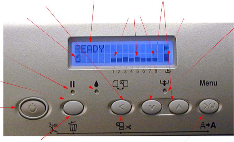
Control Panel Map
Sheet |
Roll / Sheet |
Roll Auto Cut |
|
Roll Auto Cut Off |
|
Ink Out
Paused
Pause
Power
Hold for 3 seconds to reset/clear Printer
Status |
Media Feed |
Ink Quantity |
Maintenance Tank Level |
|
Paper |
|
Out |
Hold for 3 seconds to cut |
Hold for 3 seconds to clean |
roll media |
|
Hold the 4 Arrow Buttons and Power on for F/W Download Mode.
Printer Component, Software Item, LCD Display, Printer Button |
Page 5. |
Stylus Pro 4880 Field Repair Guide |
1/17/08 |
|
|
User Menu: Press the Menu button when |
|
|
3. PRINTER STATUS. |
|
the printer displays Ready |
|
|
|
VERSION: (CURRENT FIRMWARE) |
1. PRINTER SETUP. |
|
|
|
PRINTABLE PG: (FOR EACH COLOR)MK |
ROLL COUNTER: SET ROLL LENGTH nnn.n (If enabled) |
|
(nnnnnn)PG |
||
|
INK LEFT: (FOR EACH COLOR)MK E*****F |
|||
SHEET COUNTER: SET SHEET PAGES 0-250PG (If enabled) MAINT TANK: E*****F |
||||
PLATEN GAP: *STANDARD, NARROW, WIDEST, WIDER, |
USAGE COUNT : INK (nnnn.n)ML, PPR |
|||
WIDE |
|
|
|
|
|
|
|
(nnnn.n)CM |
|
PAGE LINE: *ON, OFF |
|
|
|
|
|
|
|
USE COUNT CLR: EXEC |
|
INTERFACE: *AUTO, USB, NETWORK I/F |
|
|
|
|
|
|
|
JOB HISTORY: N0.(N) I:(nnn)ML, P:(nnn)CM |
|
CODE PAGE: *PC437, PC850, |
|
|
|
|
|
|
|
|
|
PAPER MARGIN: *DEFAULT, T/B15mm, T/B25mm,15mm, 3mmTOTAL PRINTS: (nnnn) |
||||
PPR SIZE CHK: *ON, OFF |
|
|
|
SERVICE LIFE: CUTTER, CR MOTOR, PF |
|
|
|
MOTOR, HEAD UNIT,CLEANING UNIT, |
|
PPR ALIGN CHK: *ON, OFF |
|
|
|
|
|
|
|
(E*****F) |
|
TIME OUT: *OFF, 30SEC, 60SEC, 180SEC, 300SEC |
|
|
||
|
|
|
||
CUTTER ADJ: EXEC |
4. CUSTOM PAPER. |
|||
REFRESH MRGN: *ON, OFF |
||||
SHEET SIZE CHK: *ON, OFF |
|
PAPER NUMBER: *STANDARD, NO. (1-10) |
||
AUTO NZL CK: *ON, OFF |
|
|
PLATEN GAP: STANDARD, NARROW, WIDE, |
|
AUTO CLEANING: *ON, OFF |
|
|
|
WIDER |
QUIET CUT: *OFF, ON |
|
|
THICKNESS PAT: PRINT |
|
INIT SETTINGS: EXEC |
|
|
CUT METHOD: *STANDARD, THICK (FAST, |
|
|
|
|
|
SLOW), THIN PAPER |
2. TEST PRINT. |
|
|
PPR FEED ADJ: (N.NN)% |
|
|
|
EJECT ROLLER: *AUTO, SHEET, ROLL CURLED, |
||
NOZZLE CHECK: PRINT |
|
|
|
ROLL NORMAL |
STATUS CHECK: PRINT |
|
|
DRYING TIME: (N.N)SEC |
|
JOB INFO: PRINT |
|
|
SUCTION: *STANDARD, -4, -3, -2, -1 |
|
CUSTOM PAPER: PRINT
Printer Component, Software Item, LCD Display, Printer Button |
Page 6. |
Stylus Pro 4880 Field Repair Guide |
1/17/08 |
|
|
5. MAINTENANCE |
6. Head Alignment. |
CUTTER REPL: EXEC |
PAPER THKNS: *STD, (n.n)MM |
BK Ink Change: EXEC (For Changing between Matte |
ALIGNMENT: AUTO (UNI-D, #3, #2, #1, BI- |
and Photo Black) |
D All, BI-D 2-COLOR) |
PWR CLEANING: N CLEANING Y |
MANUAL (UNI-D, BI-D All, BI- |
CLOCK SETTING: (mm/dd/yy hh:mm) |
D 2-COLOR) |
7. NETWORK SETUP: (*DISABLE, ENABLE) IP ADDRESS SETTING: AUTO, PANEL, BONJOUR: *ON, OFF
INIT NETWORK SETTING: EXECUTE
Maintenance Mode 1: Press and hold the Pause button and turn on the Printers
HEX DUMP: PRINT EXEC (In this mode, the printer prints hexadecimal values received)
LANGUAGE: *ENGLISH, DUTCH, PORTUGUE, SPANISH, GERMAN, ITALIAN, FRENCH (Control panel language)
Paper Counter: *Off, Roll, Sheet (Enables the tacking of Roll Paper usage, or count down from 250 Sheets (full tray))
UNIT: *METER, FEET/INCH (Set’s the unit of measure that the printer displays) 4CMW72: *OFF, ON (?)
CUT PRESSURE: *100% (0%-150%) (Adjusts the Paper Cutter pressure) SSCL: EXEC (Super Strong Cleaning)
ROLL PPR FEED: *OFF, ON (On saves leading edge paper)
DEFAULT PANEL: EXEC (Returns Maintenance Mode 1 settings to Factory Default)
CRTG INFO MENU: MANUFACTURER,COLOR, INK TYPE, INK CAPACITY, INK LEFT, PRODUCTION DATE, EXPIRATION DATE, INK LIFE, INK AGE (CSIC information, for each ink cartridge)
CUSTOM: 0-9 (Enabels custom modes)
Printer Component, Software Item, LCD Display, Printer Button |
Page 7. |
Stylus Pro 4880 Field Repair Guide |
1/17/08 |
|
|
Maintenance Mode 2: Press and hold the Left, Down, and Up buttons and turn on the Printer
SELF TESTING:
Test:
Version: (Displays the current firmware version) Panel: (Button tests for the control panel) Sensor: (Sensor tests for all sensors) Encoder: (Encoder tests for both encoders) Fan: (Fan tests for all fans)
Elec.: Record: Maintenance: (Usage Counters for the following devices) WasteInk, Wiper, Rubbing, Lever, Cover, Ink Lever, Cr Motor, PF Motor, PrintNumber, Cleaning, Fire A, Fire B, Fire C, Fire D, Fire E, Fire F, Fire G, Fire H, Cut, Cut Sole
Record: Error: Error (0 - 6) (Displays the last 7 errors) CSIC: Slot (1 - 8), Maintenance Tank (?)
Actuator: Cutter: [Enter], Start (Tests the cutter assembly) Actuator2: Cutter Sol, Pump Motor (Tests the following devices)
Adjustment:
Cut Adj.: Pressure: *73% (Adjusts voltage used for the cutter solenoid) PG ADJ: [Enter], Start: PG Offset *(nn) (Used for adjusting the platen gap)
Rear AD: [Enter], Start: Exc.: RearAD: (nnn nnn nnn) (For adjusting the rear paper sensor) Edge Sns Lvl: [Enter], Start: (For adjusting the “black level” of the edge sensor)
Check Nozzle: [Enter] Print: (Service level nozzle check)
Check Skew: Check Skew: (n.n)mm (Default 1.0) (Used for setting the amount of allowable skew)
Print:
Check Ptn.: [Enter] Print (Prints all alignment patterns)
Adj. Variable: [Enter] Print (Prints the numeric adjustment variables currently set)
View Counters (Displays the usage/life counter information for the following devices/operations)
Cutter, Cutter Total, Total Pages, Maint Tank, CR Motor, CR Total, PF Motor, Nozzle A, Nozzle B, Nozzle C, Nozzle D, Nozzle E, Nozzle F, Nozzle G, FL Box, Cleaner, Sponge, ASF, Feed Roller, PG
Printer Component, Software Item, LCD Display, Printer Button |
Page 8. |
Stylus Pro 4880 Field Repair Guide |
1/17/08 |
|
|
Maintenance Mode 3: Press and hold the Pause, Down, and Right buttons and turn on the Printer
SELF TESTING2:
TEST: Sensor: (Sensor tests for all sensors)
Adjustment:
Clean Head: Exec (Evacuates the ink in the Ink Tubes)
Clean Head2: Exec (?)
Counter Clear: Reset Counter? (?)
Ink Drain: Cleaning:
Std. KK0 (Weakest cleaning cycle (uses less ink)) Std. KK1 (Medium strength cleaning cycle)
Std. KK2 (Stronger cleaning cycle) Std. KK3 (Strongest cleaning cycle) Init. Fill (Forces a initial fill (prime))
Parameter:
Initialize:
All: Initialize OK? (Resets all of the following counters at once) PF Resolution: Initialize OK? (Resets this counter only) Head Record: Initialize OK? (Resets this counter only) Wiping Record: Initialize OK? (Resets this counter only) Rab. Record: Initialize OK? (Resets this counter only)
Waste Record: Initialize OK? (Resets this counter only) CRmot Record: Initialize OK? (Resets this counter only) PFmot Record: Initialize OK? (Resets this counter only) Lever Record: Initialize OK? (Resets this counter only)
Cover Record: Initialize OK? (Resets this counter only) Ink Lever Record: Initialize OK? (Resets this counter only)
Update: InkParameter: Init. Fill: (Set, Reset) (Reset, turns off the initial fill)
HeadWashFLG (?)
Mask Type: Dispersion, Regular (?)
Printer Component, Software Item, LCD Display, Printer Button |
Page 9. |
Stylus Pro 4880 Field Repair Guide |
1/17/08 |
|
|
PF BiD Adjust: (+/- n) (?)
Uni-D Trap: (On, Off) (?)
Display: Address: (Used for displaying data at specific RAM addresses)
Custom: (?)
Life: CR Motor, PF Motor, CR+PF Motor, Roller, Roller Rel, D/E Chg, Hopper, ASFLoad, Cutter, Head U/D, Head Lock, Cleaning, Print, Total Life, CR+PF+Fire, TotalLife2, TotalLife3, Check (Used for design testing of these devices and assemblies)
Service Config
MD TBL: ID = (1-7D Hex) (“Modifying parameter of media table is available”)
Clear Counters (Clears the usage/life counter information for the following devices/operations)
CUTTER REPL: EXEC
Init All: EXEC(Initializes all counters in this menu)
NVRAM: EXEC
RTC: (YY/MM/DD/HH): EXEC
Cutter: EXEC CR Motor: EXEC CR Total: EXEC PF Motor: EXEC Head: EXEC Cleaner: EXEC
Total Pages: EXEC
SPONGE: EXEC (Sponge = Boarderless Pads)
ASF: EXEC
FEED ROLLER: EXEC
PG: EXEC
CR UNIT MAINT: EXEC
CL UNIT MAINT: EXEC HEAD MAINT: EXEC
Printer Component, Software Item, LCD Display, Printer Button |
Page 10. |
Stylus Pro 4880 Field Repair Guide |
1/17/08 |
|
|
CUT UNIT MNT: EXEC
MAINT INFO: (Page 88 - 98 in the Service Manual)
Menu E: (E1 - E17), Menu R: (R1 - R9), Menu S: (S1 - S25), Menu A: (A1 - A32), Menu B: (B1 - B48), Menu P: (P1 - P42), Menu M: (M1 - M26), Menu O: (O1 - O28), Menu F: (F1 - F28), Menu N: (N1 - N22)
INIT INFO (Resets MAINT INFO menu data)
INIT. MENU E:, INIT. MENU R:, INIT. MENU S:, INIT. MENU A:, INIT. MENU B:, INIT. MENU P:, INIT. MENU M:, INIT. MENU O:, INIT. MENU F:, INIT. MENU N:
Parameter Backup Mode: (Allows Parameter backup without the Printer being online)
1.Enter Maintenance Mode 2: Press and hold the Left, Down, and Up buttons and turn on the Printer
2.Lift both (2) Ink Levers
3.Remove the Maintenance Tank
4.Move the Paper Release Lever to the released position.
Firmware Download Mode:
Hold the 4 Arrow Buttons and Power on for F/W Download Mode
Printer Component, Software Item, LCD Display, Printer Button |
Page 11. |
Stylus Pro 4880 Field Repair Guide |
1/17/08 |
|
|
Component
Replacement
Printer Component, Software Item, LCD Display, Printer Button |
Page 12. |
Stylus Pro 4880 Field Repair Guide |
1/17/08 |
|
|
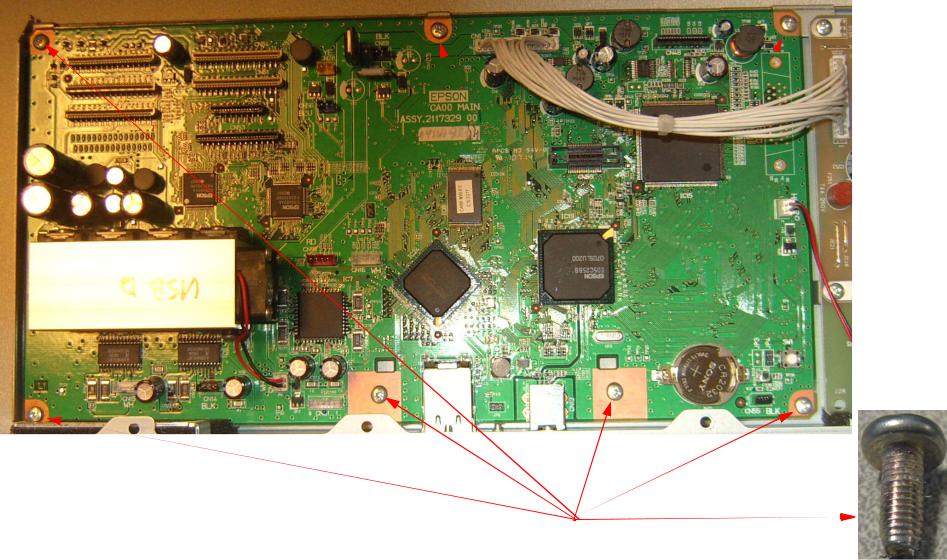
Board (Main) Installation
1.Fasten the New Board to the Housing with 7 Screws (see above) Do not fully tighten.
1.Place the New Board into the Housing.
2. Install 7 Screws (keep them loose)
Board (Main) Installation |
Printer Component, Software Item, LCD Display, Printer Button |
Page 13. |
Stylus Pro 4880 Field Repair Guide |
1/17/08 |
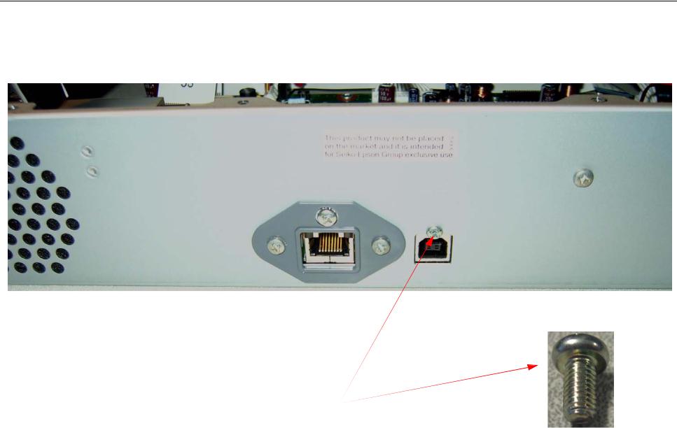
2. Install 1 Screw that fastens the USB Port to the Main Board Housing and tighten the 7 Screws that fasten the Main Board to the Housing.
1.Install 1 Screw.
2.Tighten the 7 Screws that fasten the Main Board to the Housing.
Board (Main) Installation |
Printer Component, Software Item, LCD Display, Printer Button |
Page 14. |

Stylus Pro 4880 Field Repair Guide |
1/17/08 |
|
|
3. Connect the Cables to the Main Board. Ensure that the Cables are fully seated (straight).
Connect the Cables.
Note: The numbers on the Foil Cables correspond to the Connector numbers.
Board (Main) Installation |
Printer Component, Software Item, LCD Display, Printer Button |
Page 15. |

Stylus Pro 4880 Field Repair Guide |
1/17/08 |
|
|
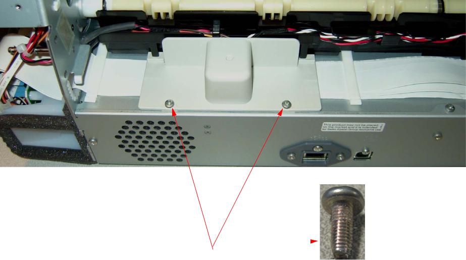
4. Install 4 Screws that fasten the Main Board Housing to the Printer.
Install 4 Screws.
Board (Main) Installation |
Printer Component, Software Item, LCD Display, Printer Button |
Page 16. |
Stylus Pro 4880 Field Repair Guide |
1/17/08 |
|
|
5. Install 2 Screws that fasten the Cable Cover to the Printer.
Install 2 Screws
Board (Main) Installation |
Printer Component, Software Item, LCD Display, Printer Button |
Page 17. |
Stylus Pro 4880 Field Repair Guide |
1/17/08 |
|
|
6.Write current Firmware to the Main Board. (Detailed directions for writing firmware to the Main Board are in the Firmware Update chapter located in the Reference Section of the Field Repair Guide.
6.1Open the FW/Update.exe, and prepare to send the current firmware version to the Printer.
6.2Turn on the Printer while depressing the Left, Up, Down, and Right arrow buttons, The Printer will display
UPDATE F/W.
6.3Send the current firmware to the Printer.
If the Printer’s Parameters are not available skip step 7, and follow step 8 and 9.
7.Re-Install the Printer’s parameters using the Parameter Backup / Restore Utility (Nvram.exe)
7.1Perform the RTC&USBID&IEEE1394ID Adjustment.
8.Install the appropriate generic Printer parameters using the Parameter Backup / Restore Utility (Nvram.exe)
Note: If the new Board does not have any parameters, the Printer may not function well enough to allow alignments, paper loading, nozzle check, or the rest of step 18. Generic parameters are a set of working parameters from another printer. They are available for download at: https:// www.epsoninsider.com listed under the Printer name, as Generic NVRAM Backup. They come in 2 variations (4880 Matte Black, 4880 Photo Black).
9.Perform the following operations in the order listed.
9.1Perform the RTC&USBID Adjustment.
9.2Perform the Rear Sensor Calibration.
9.3Perform the Cutter Pressure adjustment.
9.4Perform the Platen Gap adjustment.
9.5Enter the Head Rank ID (Print Head calibration values).
Board (Main) Installation |
Printer Component, Software Item, LCD Display, Printer Button |
Page 18. |
Stylus Pro 4880 Field Repair Guide |
1/17/08 |
|
|
9.6Perform the Multi Sensor Level Adjustment.
9.7Perform the Multi Sensor Adjustment.
9.8Perform the Auto Bi-D Adjustment.
9.9Perform the Auto Uni-D Adjustment.
9.10Perform the Platen Position Adjustment
9.11Perform the 980mm Feed Adjustment, or Multi Sensor Auto PF Adjustment.
9.12Perform the T&B&S (Roll Paper) Adjustment.
9.13Perform the T&B&S (Cut Sheet) Adjustment.
9.14Perform the Writing MAC Address Adjustment.
Board (Main) Installation |
Printer Component, Software Item, LCD Display, Printer Button |
Page 19. |

Stylus Pro 4880 Field Repair Guide |
1/17/08 |
|
|
Board (Main) Removal
1. Back up the Printer’s parameters using the Parameter Backup / Restore Utility (Nvram.exe).
Note: If the Printer’s parameters can not be “backed up”, print out the Print Head Calibration value (Head Rank). The Print Head Calibration value is printed on the Service Level Nozzle Check (Maintenance Mode 2: Self Testing: Adjustment: Check Nozzle).
2.Turn off the Printer and UNPLUG from AC.
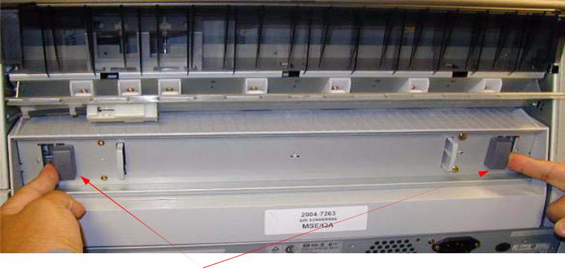
3.Remove the Rear Paper Guide.
Push the 2 Grey Tabs and remove the Rear Paper Guide
Board (Main) Removal |
Printer Component, Software Item, LCD Display, Printer Button |
Page 20. |
Stylus Pro 4880 Field Repair Guide |
1/17/08 |
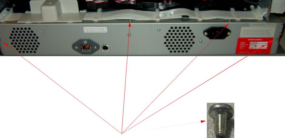
4. Remove the 2 Screws fastening the Cable Cover.
Remove 2 Screws
Board (Main) Removal |
Printer Component, Software Item, LCD Display, Printer Button |
Page 21. |
Stylus Pro 4880 Field Repair Guide |
1/17/08 |
|
|
5. Remove the 4 Screws fastening the Main Board Housing.
Remove 4 Screws.
Board (Main) Removal |
Printer Component, Software Item, LCD Display, Printer Button |
Page 22. |

Stylus Pro 4880 Field Repair Guide |
1/17/08 |
|
|
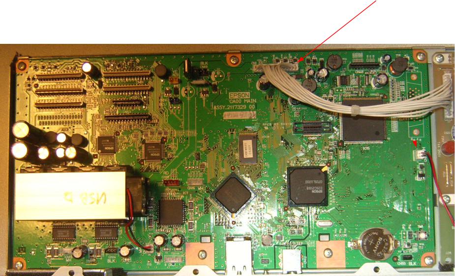
6. Slide out the Main Board Housing, and disconnect the Cables. |
|
Slide out the Main Board Housing, and disconnect the Cables.
Note: The numbers on the Foil Cables correspond to the Connector numbers.
Board (Main) Removal |
Printer Component, Software Item, LCD Display, Printer Button |
Page 23. |

Stylus Pro 4880 Field Repair Guide |
1/17/08 |
|
|
7. Remove the 1 Screw that fastens the USB Port to the Main Board Housing.
Remove 1 Screw.
Board (Main) Removal |
Printer Component, Software Item, LCD Display, Printer Button |
Page 24. |
Stylus Pro 4880 Field Repair Guide |
1/17/08 |
|
|
8. Unplug 2 Cables.
Unplug 2 Cables.
Board (Main) Removal |
Printer Component, Software Item, LCD Display, Printer Button |
Page 25. |

Stylus Pro 4880 Field Repair Guide |
1/17/08 |
|
|
9. Remove 7 Screws, and remove the Main Board from the Housing.
1. Remove 7 Screws.
2. Separate the Board from the Housing.
Board (Main) Removal |
Printer Component, Software Item, LCD Display, Printer Button |
Page 26. |
Stylus Pro 4880 Field Repair Guide |
1/17/08 |
|
|
Board (Power Supply) Removal
1.Turn off the Printer and UNPLUG from AC.
2.Remove the Rear Paper Guide.
Push the 2 Grey Tabs and remove the Rear Paper Guide
Board (Power Supply) Removal |
Printer Component, Software Item, LCD Display, Printer Button |
Page 27. |

Stylus Pro 4880 Field Repair Guide |
1/17/08 |
3. Remove the 2 Screws fastening the Cable Cover.
Remove 2 Screws
Board (Power Supply) Removal |
Printer Component, Software Item, LCD Display, Printer Button |
Page 28. |

Stylus Pro 4880 Field Repair Guide |
1/17/08 |
|
|
4. Remove the 4 Screws fastening the Main Board Housing.
Remove 4 Screws.
Board (Power Supply) Removal |
Printer Component, Software Item, LCD Display, Printer Button |
Page 29. |
Stylus Pro 4880 Field Repair Guide |
1/17/08 |
|
|
5. Slide out the Main Board Housing, and disconnect the Cables. |
|
Slide out the Main Board Housing, and disconnect the Cables.
Note: The numbers on the Foil Cables correspond to the Connector numbers.
Board (Power Supply) Removal |
Printer Component, Software Item, LCD Display, Printer Button |
Page 30. |
Loading...