


 Loading...
SAG586505000
SAG586505500
System Application Guide
Spec. No. 586505000 (Model LMS1000)
Spec. No. 586505500 (Model LMS1000)
Issue AZ, April 7, 2014
SYSTEM OVERVIEW |
Home |
|
Description: A programmable monitoring, controlling, and data acquisition system designed for use in telecommunications power sites.
•Consists of a Main Cabinet which holds up to ten input/output circuit cards, in a cabinet size that occupies two 19" or 23" relay rack spaces. For system expansion and/or to monitor points at other locations, Supplemental (Expansion) Cabinets are available. Each Expansion Cabinet holds up to ten input/output circuit cards, in a cabinet size that occupies two 19" or 23" relay rack spaces. Also available are Expansion Assemblies which provide an input circuit card equipped with a fixed number of analog and binary input points in a sheet metal housing. These assemblies can be mounted inside customer equipment. The Main Cabinet, Expansion Cabinets, and Expansion Assemblies are interconnected via the LMS1000 network.
•The Main Cabinet and Expansion Cabinets can be equipped with various input circuit cards to monitor a variety of analog, binary, and temperature points. The Expansion Assemblies are always equipped with an input circuit card to monitor a fixed number of analog and binary points.
•LMS1000 collects data from the input circuit cards. The data collected is used for alarm processing and reporting, and to provide statistics.
•LMS1000 is capable of reporting alarm conditions to a remote terminal, pager, or Email address. For remote terminal or pager notification, the Main CPU circuit card must be equipped with the optional modem. Two types of alarm reporting mechanisms are provided, System Alarm Reporting and Individual User Alarm Reporting.
Expansion Assembly
Main Cabinet
(Expansion Cabinet Similar)
Page 1 of 62
This document is property of Emerson Network Power, Energy Systems, North America, Inc. and contains confidential and proprietary information owned by Emerson Network Power, Energy Systems, North America, Inc. Any copying, use, or disclosure of it without the written permission of Emerson Network Power, Energy Systems, North America, Inc. is strictly prohibited.

SAG586505000 |
System Application Guide |
|
SAG586505500 |
Spec. No. 586505000 (Model LMS1000) |
|
Issue AZ, April 7, 2014 |
Spec. No. 586505500 (Model LMS1000) |
|
• |
LMS1000 is capable of reporting alarm conditions via SNMP traps over Ethernet |
Home |
|
||
|
or via TL1 (over Ethernet) when the 'TL1 over Ethernet' option is ordered. TL1 |
|
|
is also available via a serial connection in 'direct mode'. |
|
•The Main CPU circuit card provides programmable LEDs to allow local indication of alarm conditions or occurrences. For remote indication, the Main and/or Expansion Cabinets can be equipped with output circuit cards which provide programmable relays. These relays may also be used to control other equipment.
•LMS1000 easily interfaces with the MCA of Vortex® Power Systems (VPS) and NetSure™ Power Systems (NPS). This interface allows an LMS1000 user to remotely monitor, adjust, and control the Power System via LMS1000; plus easily use the features of LMS1000 with the Power System. Separate analog, binary, and relay circuit cards do not have to be supplied for this interface. Analog, binary, relay, and temperature circuit cards (I/O cards) can be provided to monitor equipment external to the Power System. In a VPS/NPS, one simple cable connection between the Main Cabinet and the VPS/NPS completes the interconnections required. Note that the LMS1000 is factory integrated into Spec. Nos. 582140000, 582140001, and 582126100 NetSure Power Systems.
Note that Spec. Nos. 582140000, 582140001, and 582126100 NetSure Power Systems do not use the LMS1000 Cabinets. The LMS1000 is factory integrated into the Power Systems. Note that LMS1000 I/O circuit card mounting positions are provided inside a 582140000, 582140001, and 582126100 NetSure Power System.
•LMS1000 can be accessed via a local port, a modem port (when optional modem is ordered), an optional TL1 port, and an Ethernet port (for Telnet access, Web access, SNMP access, optional TL1 access, and Email alarm reporting). A local front panel display option is also available.
•Available software options include…
Power Metering Energy Management*
Rectifier/PCU Sequencing* TL1/X.25
TL1 (over Ethernet) Gateway Port
LMS Dual MCA Interface
*Note: LMS1000 Energy Management and Sequencing features are not for use in the Spec. Nos. 582140000, 582140001, and 582126100 Power Systems.
•Available specialty interfaces include…
Door Access Controller Interface External GPS Modem Interface AC Analyzer Interface
Page 2 of 62
This document is property of Emerson Network Power, Energy Systems, North America, Inc. and contains confidential and proprietary information owned by Emerson Network Power, Energy Systems, North America, Inc. Any copying, use, or disclosure of it without the written permission of Emerson Network Power, Energy Systems, North America, Inc. is strictly prohibited.

System Application Guide |
SAG586505000 |
|
Spec. No. 586505000 (Model LMS1000) |
SAG586505500 |
|
Spec. No. 586505500 (Model LMS1000) |
Issue AZ, April 7, 2014 |
|
|
|
Home |
Family: |
NetSure™ |
|
Spec. No.: |
586505000 and 586505500 |
|
Model: |
LMS1000 |
|
Agency Approval: |
UL Recognized to UL 1950 |
|
|
CSA 22.2, No. 950 |
|
Framework Type: |
Main and Expansion Cabinets: Mounted in a Customer Provided 19 |
|
|
or 23 Inch Wide Rack |
|
Mounting Width: |
Main and Expansion Cabinets: 19 or 23 Inch (Relay Rack Mounting) |
|
Mounting Depth: |
Main and Expansion Cabinets: 13.250 Inches |
|
Mounting Height: |
Main and Expansion Cabinets: 3.470 Inches |
|
Access: |
Front and Rear for Installation and Maintenance, Front for Operation |
|
Color: |
586505000: Off-White |
|
|
586505500: Textured Gray |
|
Environment: |
-40°C to +60°C (-40°F to +140°F) |
|
Page 3 of 62
This document is property of Emerson Network Power, Energy Systems, North America, Inc. and contains confidential and proprietary information owned by Emerson Network Power, Energy Systems, North America, Inc. Any copying, use, or disclosure of it without the written permission of Emerson Network Power, Energy Systems, North America, Inc. is strictly prohibited.

SAG586505000 |
System Application Guide |
SAG586505500 |
Spec. No. 586505000 (Model LMS1000) |
Issue AZ, April 7, 2014 |
Spec. No. 586505500 (Model LMS1000) |
586505000 and 586505500 |
Home |
|
Main Cabinet |
List 1: |
LMS1000 Monitoring System |
List 2: |
LMS1000 Monitoring System |
(Expansion |
|
(MAIN CABINET - 19"/23") |
|
(MAIN CABINET - 23" only) |
Cabinets |
|
|
|
|
Similar) |
List 6: |
LMS1000 Monitoring System |
List 7: |
LMS1000 Monitoring System |
(19" Cabinet |
|
(EXPANSION CABINETS - 19"/23") |
|
(EXPANSION CABINETS - 23" only) |
Shown) |
List 10: LMS1000 Monitoring System |
|
|
|
|
|
|
||
|
|
(EXPANSION ASSEMBLIES) (not shown) |
|
|
P/O List 1 and 6: CPU Circuit Card |
List 92: VPS MCA Interface Cable, |
Front Door |
||
|
Opened in |
|||
|
Customer Specified Length |
|||
|
Illustration |
|||
List 70: Modem Circuit Card |
List 93: VPS MCA Interface Cable |
|||
|
||||
(MAIN CABINET ONLY) |
Termination Kit |
|
|
|
|
List 94: VPS MCA Interface Cable, |
|
||
|
Pre-Assembled, 6' |
|
|
|
Standard Software Features |
Available Specialty Interfaces |
|
|
|
WEB Interface |
List 80: Door Access Controller |
|
|
|
SNMP |
Interface |
Determines |
||
|
List 84: External GPS Modem |
Earlier vs. Later |
||
|
Version 19" Cabinets |
|||
Available Software Options |
Interface |
|
|
|
|
|
|
||
List 78: LMS Dual MCA Interface
Software Option
List 79: Gateway Port Software Option
List 82: PCU/Rectifier Sequencing
Software Option
List 83: Energy Management Software Option
List 86: TL1/X.25 Software Option
List 87: Power Metering Software Option
List 88: Local Port Redirection
List 90: TL1 (over Ethernet) Software Option
List 85: AC Analyzer Interface
Front Panel Display Option
List 60: (for use in later version 19" cabinets)
List 61: (for use in earlier
version 19" cabinets)
List 62: (for use in 23" cabinets) (requires 10th I/O slot)
List 63: (for use in 23" cabinets) (DOES NOT require 10th I/O slot)
I/O Slot #10 has a Larger (30 pos.) Connector
I/O Slot #10 is the Same as the Other I/O Slots
Page 4 of 62
This document is property of Emerson Network Power, Energy Systems, North America, Inc. and contains confidential and proprietary information owned by Emerson Network Power, Energy Systems, North America, Inc. Any copying, use, or disclosure of it without the written permission of Emerson Network Power, Energy Systems, North America, Inc. is strictly prohibited.
System Application Guide |
|
|
|
|
|
|
|
|
|
|
|
|
|
|
|
|
|
|
|
|
|
|
|
|
|
|
|
|
|
|
|
|
|
|
|
|
|
|
|
|
|
|
|
|
|
|
|
|
|
|
|
|
|
|
|
|
|
|
|
|
|
|
|
|
|
|
|
|
|
|
|
|
|
|
|
|
|
|
|
|
|
|
|
|
|
SAG586505000 |
||||||||||||||||||||||||||||||||||||||||||||||||||||||||||||||||||||||||||||||||||||||||||||||||||||||||||||||||||||||||||||||||||||
Spec. No. 586505000 (Model LMS1000) |
|
|
|
|
|
|
|
|
|
|
|
|
|
|
|
|
|
|
|
|
|
|
|
|
|
|
|
|
|
|
|
|
|
|
|
|
|
|
|
|
|
|
|
|
|
|
|
|
|
|
|
|
|
|
|
|
|
|
|
|
|
|
|
|
|
|
|
|
|
|
|
|
|
|
|
|
|
|
|
|
|
|
|
|
|
SAG586505500 |
||||||||||||||||||||||||||||||||||||||||||||||||||||||||||||||||||||||||||||||||||||||||||||||||||||||||||||||||||||||||||||||||||||
Spec. No. 586505500 (Model LMS1000) |
|
|
|
|
|
|
|
|
|
|
|
|
|
|
|
|
|
|
|
|
|
|
|
|
|
|
|
|
|
|
|
|
|
|
|
|
|
|
|
|
|
|
|
|
|
|
|
|
|
|
|
|
|
|
|
|
|
|
|
|
|
|
|
|
|
|
|
|
|
|
|
|
Issue AZ, April 7, 2014 |
|||||||||||||||||||||||||||||||||||||||||||||||||||||||||||||||||||||||||||||||||||||||||||||||||||||||||||||||||||||||||||||||||||||||||||||||||
|
|
|
|
|
|
|
|
|
|
|
|
|
|
|
|
|
|
|
|
|
|
|
|
|
|
|
|
|
|
|
|
|
|
|
|
|
|
|
|
|
|
|
|
|
|
|
|
|
|
|
|
|
|
|
|
|
|
|
|
|
|
|
|
|
|
|
|
|
|
|
|
|
|
|
|
|
|
|
|
|
|
|
|
|
|
|
|
|
|
|
|
|
|
|
|
|
|
|
|
|
|
|
|
|
|
|
|
|
|
|
|
|
|
|
|
|
|
|
|
|
|
|
|
|
|
|
|
|
|
|
|
|
|
|
|
|
|
|
|
|
|
|
|
|
|
|
|
|
|
|
|
|
|
|
|
|
|
|
|
|
|
|
|
|
|
|
|
|
|
|
|
|
|
|
|
|
|
|
|
|
|
|
|
|
|
|
|
|
|
|
|
|
|
|
|
|
|
|
|
|
|
|
|
|
|
|
|
|
|
|
|
|
|
|
Home |
|||
|
|
|
|
|
|
|
|
|
|
|
|
|
|
|
|
|
|
|
|
|
|
|
|
|
|
|
|
|
|
|
|
|
|
|
|
|
|
|
|
|
|
|
|
|
|
|
|
|
|
|
|
|
|
|
|
|
|
|
|
|
|
|
|
|
|
|
|
|
|
|
|
|
|
|
|
|
|
|
|
|
|
|
|
|
|
|
|
|
|
|
|
|
|
|
|
|
|
|
|
|
|
|
|
|
|
|
|
|
|
|
|
|
|
|
|
|
|
|
|
|
|
|
|
|
|
|
|
|
|
|
|
|
|
|
|
|
|
|
|
|
|
|
|
|
|
|
|
|
|
|
|
|
|
|
|
|
|
|
|
|
|
|
|
|
|
|
|
|
|
|
|
|
|
|
|
|
|
|
|
|
|
|
|
|
|
|
|
|
|
|
|
|
|
|
|
|
|
|
|
|
|
|
|
|
|
|
|
|
|
|
|
|
|
|
|
|
|
|
|
|
|
|
|
|
|
|
|
|
|
|
|
|
|
|
|
|
|
|
|
|
|
|
|
|
|
|
|
|
|
|
|
|
|
|
|
|
|
|
|
|
|
|
|
|
|
|
|
|
|
|
|
|
|
|
|
|
|
|
|
|
|
|
|
|
|
|
|
|
|
|
|
|
|
|
|
|
|
|
|
|
|
|
|
|
|
|
|
|
|
|
|
|
|
|
|
|
|
|
|
|
|
|
|
|
|
|
|
|
|
|
|
|
|
|
|
|
|
|
|
|
|
|
|
|
|
|
|
|
|
|
|
|
|
|
|
|
|
|
|
|
|
|
|
|
|
|
|
|
|
|
|
|
|
|
|
|
|
|
|
|
|
|
|
|
|
|
|
|
|
|
|
|
|
|
|
|
|
|
|
|
|
|
|
|
|
|
|
|
|
|
|
|
|
|
|
|
|
|
|
|
|
|
|
|
|
|
|
|
|
|
|
|
|
|
|
|
|
|
|
|
|
|
|
|
|
|
|
|
|
|
|
|
|
|
|
|
|
|
|
|
|
|
|
|
|
|
|
|
|
|
|
|
|
|
|
|
|
|
|
|
|
|
|
|
|
|
|
|
|
|
|
|
|
|
|
|
|
|
|
|
|
|
|
|
|
|
|
|
|
|
|
|
|
|
|
|
|
|
|
|
|
|
|
|
|
|
|
|
|
|
|
|
|
|
|
|
|
|
|
|
|
|
|
|
|
|
|
|
|
|
|
|
|
|
|
|
|
|
|
|
|
|
|
|
|
|
|
|
|
|
|
|
|
|
|
|
|
|
|
|
|
|
|
|
|
|
|
|
|
|
|
|
|
|
|
|
|
|
|
|
|
|
|
|
|
|
|
|
|
|
|
|
|
|
|
|
|
|
|
|
|
|
|
|
|
|
|
|
|
|
|
|
|
|
|
|
|
|
|
|
|
|
|
|
|
|
|
|
|
|
|
|
|
|
|
|
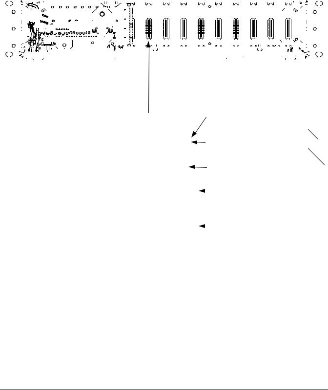
Main Cabinet |
Front Door |
(Expansion Cabinets Similar) |
Opened in |
(19" Cabinet Shown) |
Illustration |
Available Input/Output (I/O) |
List BA, BB, and BC: Current Limit |
|
|
|
Resistor Kits |
|
|
Circuit Cards |
|
|
|
List BE, BF, |
|
|
|
List 20: Four (4) Input Analog |
|
|
|
and P/N 535135: |
In-Line Fuse |
|
|
Circuit Card |
|
||
|
Kits |
|
|
|
|
|
|
List 21: Eight (8) Input |
List ST and SU: |
Temperature |
|
Temperature Circuit |
|
||
Card |
|
Sensors |
|
List 22: Eight (8) Input Analog |
|
|
|
|
|
|
|
Circuit Card |
|
|
|
List 23: Twelve (12) Input |
|
|
|
Analog Circuit Card |
|
|
|
for Measuring |
|
|
|
|
|
|
|
Individual Battery Cell |
|
|
|
Voltages |
|
|
|
List 30: Four (4) Input Binary |
|
|
|
Circuit Card |
|
|
|
List 31: Eight (8) Input Binary |
|
|
|
Circuit Card |
|
|
|
List 40: Four (4) Output |
SEE ALSO |
|
|
Form-C Relay Circuit |
|
||
|
|
|
|
Card |
System Overview |
|
|
|
Table of Contents |
|
|
|
List Descriptions |
|
|
Accessory Descriptions
Specifications
Dimensional Drawings
Related Documentation
Page 5 of 62
This document is property of Emerson Network Power, Energy Systems, North America, Inc. and contains confidential and proprietary information owned by Emerson Network Power, Energy Systems, North America, Inc. Any copying, use, or disclosure of it without the written permission of Emerson Network Power, Energy Systems, North America, Inc. is strictly prohibited.

SAG586505000 |
|
|
|
|
System Application Guide |
||
SAG586505500 |
|
|
|
Spec. No. 586505000 (Model LMS1000) |
|||
Issue AZ, April 7, 2014 |
|
|
Spec. No. 586505500 (Model LMS1000) |
||||
TABLE OF CONTENTS |
|
|
|
|
|
||
System |
|
List |
Accessory |
|
Physical Size |
Related |
|
Overview |
Picture |
Descriptions |
Descriptions |
Specifications |
Information |
Documentation |
|
SYSTEM OVERVIEW................................................................................................................................................. |
|
|
|
|
|
1 |
|
TABLE OF CONTENTS............................................................................................................................................. |
|
|
|
|
|
6 |
|
LIST DESCRIPTIONS................................................................................................................................................ |
|
|
|
|
|
8 |
|
List 1: Common Equipment for the LMS1000 Main Cabinet........................................................................... |
|
|
8 |
||||
List 2: Common Equipment for the LMS1000 Main Cabinet........................................................................... |
|
|
8 |
||||
List 6: Common Equipment for One (1) LMS1000 Expansion Cabinet .......................................................... |
|
|
9 |
||||
List 7: Common Equipment for One (1) LMS1000 Expansion Cabinet .......................................................... |
|
|
9 |
||||
List 10: Common Equipment for One (1) LMS1000 Expansion Assembly ................................................... |
|
10 |
|||||
List 20: Four (4) Input Analog Circuit Card ................................................................................................... |
|
|
|
10 |
|||
List 21: Eight (8) Input Temperature Circuit Card ......................................................................................... |
|
|
|
11 |
|||
List 22: Eight (8) Input Analog Circuit Card................................................................................................... |
|
|
|
11 |
|||
List 23: Twelve (12) Input Analog Circuit Card for Measuring Individual Battery Cell Voltages .................... |
11 |
||||||
List 30: Four (4) Input Binary Circuit Card .................................................................................................... |
|
|
|
12 |
|||
List 31: Eight (8) Input Binary Circuit Card.................................................................................................... |
|
|
|
12 |
|||
List 40: Four (4) Output Form-C Relay Circuit Card ..................................................................................... |
|
|
|
13 |
|||
List 60: LMS1000 Display Option (for use in later version 586505000 19" cabinets)................................... |
|
13 |
|||||
List 61: LMS1000 Display Option (for use in earlier version 586505000 19" cabinets)................................ |
|
14 |
|||||
List 62: LMS1000 Display Option (for use in 586505000/586505500 23" cabinets) .................................... |
|
15 |
|||||
List 63: LMS1000 Display Option (for use in 586505000/586505500 23" cabinets) .................................... |
|
15 |
|||||
List 70: Modem Circuit Card.......................................................................................................................... |
|
|
|
|
16 |
||
List 78: LMS Dual MCA Interface Software Option....................................................................................... |
|
|
|
16 |
|||
List 79: Gateway Port Software Option......................................................................................................... |
|
|
|
16 |
|||
List 80: Door Access Controller (DAC) Interface .......................................................................................... |
|
|
|
17 |
|||
List 82: PCU/Rectifier Sequencing Software Option..................................................................................... |
|
|
|
17 |
|||
List 83: Energy Management Software Option ............................................................................................. |
|
|
|
17 |
|||
List 84: External GPS Modem Interface........................................................................................................ |
|
|
|
18 |
|||
List 85: AC Analyzer Interface....................................................................................................................... |
|
|
|
|
18 |
||
List 86: TL1/X.25 Software Option ................................................................................................................ |
|
|
|
|
18 |
||
List 87: Power Metering Software Option ..................................................................................................... |
|
|
|
19 |
|||
List 88: Local Port Redirection to OEM 1 Port Option................................................................................... |
|
|
|
19 |
|||
List 90: TL1 (over Ethernet) Software Option ............................................................................................... |
|
|
|
19 |
|||
List 92: MCA Interface Cable, Customer Specified Length .......................................................................... |
|
|
19 |
||||
List 93: MCA Interface Cable Termination Kit............................................................................................... |
|
|
|
20 |
|||
List 94: MCA Interface Cable, Pre-assembled.............................................................................................. |
|
|
|
20 |
|||
List BA: Current Limit Resistor Kit................................................................................................................. |
|
|
|
|
20 |
||
List BB: Current Limit Resistor Kit................................................................................................................. |
|
|
|
|
20 |
||
List BC: Current Limit Resistor Kit................................................................................................................. |
|
|
|
|
21 |
||
List BE: In-Line Fuse Kit................................................................................................................................ |
|
|
|
|
21 |
||
List BF: In-Line Fuse Kit................................................................................................................................ |
|
|
|
|
21 |
||
List ST: Temperature Sensor ........................................................................................................................ |
|
|
|
|
21 |
||
List SU: Temperature Sensor........................................................................................................................ |
|
|
|
|
21 |
||
ACCESSORY DESCRIPTIONS............................................................................................................................... |
|
|
|
|
23 |
||
In-Line Fuse Kit, P/N 535135 ............................................................................................................................ |
|
|
|
|
23 |
||
Replacement CPU Memory Backup Battery ................................................................................................... |
|
|
|
23 |
|||
LMS1000 Network Cables................................................................................................................................. |
|
|
|
|
23 |
||
|
|
|
Page 6 of 62 |
|
|
|
|
This document is property of Emerson Network Power, Energy Systems, North America, Inc. and contains confidential and proprietary information owned by Emerson Network Power, Energy Systems, North America, Inc. Any copying, use, or disclosure of it without the written permission of Emerson Network Power, Energy Systems, North America, Inc. is strictly prohibited.

System Application Guide |
SAG586505000 |
|
Spec. No. 586505000 (Model LMS1000) |
SAG586505500 |
|
Spec. No. 586505500 (Model LMS1000) |
Issue AZ, April 7, 2014 |
|
130VDC Monitoring Wire Harness ................................................................................................................... |
|
24 |
SPECIFICATIONS.................................................................................................................................................... |
|
25 |
1. 586505000/586505500 LMS1000 System .................................................................................................... |
|
25 |
1.1 Environmental Ratings ............................................................................................................................. |
|
25 |
1.2 Firmware Specifications ........................................................................................................................... |
|
25 |
1.3 Node Specifications.................................................................................................................................. |
|
25 |
1.4 Software Features .................................................................................................................................... |
|
26 |
1.5 Available Software Options ...................................................................................................................... |
|
37 |
1.6 Specialty Interfaces .................................................................................................................................. |
|
41 |
2. 586505000/586505500 LMS1000 Main Cabinet........................................................................................... |
|
42 |
2.1 Input Ratings ............................................................................................................................................ |
|
42 |
2.2 Mounting................................................................................................................................................... |
|
42 |
2.3 I/O Circuit Card Mounting Positions ......................................................................................................... |
|
42 |
2.4 CPU Circuit Card, Part No. 545476 (used in 586505000/586505500) and 545558 (used in |
|
|
582140000, 582140001, and 582126100)..................................................................................................... |
|
42 |
2.5 LMS1000 Front Panel Display Option...................................................................................................... |
|
45 |
2.6 Optional Modem Circuit Card, Part No. 508951....................................................................................... |
|
46 |
3. 586505000/586505500 LMS1000 Expansion Cabinet................................................................................. |
|
50 |
3.1 Input Ratings ............................................................................................................................................ |
|
50 |
3.2 Mounting................................................................................................................................................... |
|
50 |
3.3 I/O Circuit Card Mounting Positions ......................................................................................................... |
|
50 |
3.4 CPU Circuit Card, Part No. 506153 (also used in 582140000, 582140001, and 582126100 |
|
|
Secondary Bays)............................................................................................................................................ |
|
50 |
4. 586505000/586505500 LMS1000 Expansion Assembly............................................................................. |
|
50 |
4.1 Input Ratings ............................................................................................................................................ |
|
50 |
4.2 Mounting................................................................................................................................................... |
|
50 |
4.3 I/O Connector Pinouts .............................................................................................................................. |
|
50 |
4.4 CPU Circuit, P/O Part No. 507606 ........................................................................................................... |
|
50 |
5. Input/Output (I/O) Circuit Cards .................................................................................................................. |
|
51 |
5.1 Four (4) Input Analog Circuit Card, Part No. 506336............................................................................... |
|
51 |
5.2 Eight (8) Input Analog Circuit Card, Part No. 514528 .............................................................................. |
|
51 |
5.3 Twelve (12) Input Analog Circuit Card, Part No. 520838......................................................................... |
|
51 |
5.4 Four (4) Input Binary Circuit Card, Part No. 506332................................................................................ |
|
51 |
5.5 Eight (8) Input Binary Circuit Card, Part No. 506334 ............................................................................... |
|
52 |
5.6 Four (4) Output Form-C Relay Circuit Card, Part No. 506335................................................................. |
|
52 |
5.7 Eight (8) Input Temperature Circuit Card, Part No. 506333..................................................................... |
|
52 |
PHYSICAL SIZE INFORMATION ............................................................................................................................ |
|
53 |
Overall Dimensions (586505000 Main [List 1] and Expansion [List 6] Cabinets) ....................................... |
|
53 |
Overall Dimensions (586505000/586505500 Main [List 2] and Expansion [List 7] Cabinets) .................... |
54 |
|
Overall Dimensions (586505000/586505500 Expansion Assembly)............................................................. |
|
55 |
Connector Locations (586505000/586505500 Main Cabinet) ........................................................................ |
|
56 |
Connector Locations (586505000/586505500 Expansion Cabinet) .............................................................. |
|
57 |
Connector Locations (586505000/586505500 Expansion Assembly) .......................................................... |
|
58 |
RELATED DOCUMENTATION................................................................................................................................ |
|
61 |
REVISION RECORD................................................................................................................................................ |
|
62 |
Page 7 of 62
This document is property of Emerson Network Power, Energy Systems, North America, Inc. and contains confidential and proprietary information owned by Emerson Network Power, Energy Systems, North America, Inc. Any copying, use, or disclosure of it without the written permission of Emerson Network Power, Energy Systems, North America, Inc. is strictly prohibited.

SAG586505000 |
System Application Guide |
|
SAG586505500 |
Spec. No. 586505000 (Model LMS1000) |
|
Issue AZ, April 7, 2014 |
Spec. No. 586505500 (Model LMS1000) |
|
LIST DESCRIPTIONS |
|
Home |
|
|
|
List 1: Common Equipment for the LMS1000 Main Cabinet
Features
♦ Provides the LMS1000 MAIN CABINET (19"/23" relay rack mounting)
(off-white).
♦ Refer to the "Specifications" section of this document for further information.
Restrictions
Not for use in Spec. Nos. 582140000, 582140001, and 582126100 Power Systems.
Ordering Notes
1)Order 586505000 List 1 (off-white).
2)Order Analog Circuit Cards as required per List 20, List 22, and List 23.
3)Order Temperature Circuit Cards as required per List 21.
4)Order Binary Circuit Cards as required per List 30 and List 31.
5)Order Relay Circuit Cards as required per List 40.
6)Order Modem Circuit Card as required per List 70.
7)Order Software Options as required per List 78, 79, 81, 82, 83, 86future_release, 87, 88, 89, and/or 90.
8)Order Specialty Interfaces as required per List 80, List 84, and/or List 85.
9)Order a MCA interconnect cable if required per List 92 and List 93, or List 94.
10)Order Front Panel Display option as required per List 60.
11)Order Accessories as required per the "ACCESSORY" section.
List 2: Common Equipment for the LMS1000 Main Cabinet
Features
♦Provides the LMS1000 MAIN CABINET (23" only
relay rack mounting) (586505000 off-white) (586505500 gray).
♦ Refer to the "Specifications" section of this document for further information.
Restrictions
Not for use in Spec. Nos. 582140000, 582140001, and 582126100 Power Systems.
Ordering Notes
1)Order 586505000 List 2 (off-white) or 586505500 List 2 (gray).
2)Order Analog Circuit Cards as required per List 20, List 22, and List 23.
3)Order Temperature Circuit Cards as required per List 21.
4)Order Binary Circuit Cards as required per List 30 and List 31.
5)Order Relay Circuit Cards as required per List 40.
6)Order Modem Circuit Card as required per List 70.
7)Order Software Options as required per List 78, 79, 81, 82, 83, 86future_release, 87, 88, 89, and/or 90.
8)Order Specialty Interfaces as required per List 80, List 84, and/or List 85.
Page 8 of 62
This document is property of Emerson Network Power, Energy Systems, North America, Inc. and contains confidential and proprietary information owned by Emerson Network Power, Energy Systems, North America, Inc. Any copying, use, or disclosure of it without the written permission of Emerson Network Power, Energy Systems, North America, Inc. is strictly prohibited.
System Application Guide |
SAG586505000 |
||
Spec. No. 586505000 (Model LMS1000) |
SAG586505500 |
||
Spec. No. 586505500 (Model LMS1000) |
Issue AZ, April 7, 2014 |
||
9) |
Order a MCA interconnect cable if required per List 92 and List 93, or List 94. |
|
Home |
|
|
||
10) |
Order Front Panel Display option as required per List 62 or List 63. |
|
|
11) |
Order Accessories as required per the "ACCESSORY" section. |
|
|
List 6: Common Equipment for One (1) LMS1000 Expansion Cabinet
Features
♦ Provides one (1) LMS1000 EXPANSION CABINET (19"/23" relay rack mounting) (off-white).
♦ Refer to the "Specifications" section of this document for further information.
Restrictions
Not for use in Spec. Nos. 582140000, 582140001, and 582126100 Power Systems.
Ordering Notes
1)Order 586505000 List 6 (off-white).
2)Order Analog Circuit Cards as required per List 20 and List 22.
3)Order Temperature Circuit Cards as required per List 21.
4)Order Binary Circuit Cards as required per List 30 and List 31.
5)Order Relay Circuit Cards as required per List 40.
List 7: Common Equipment for One (1) LMS1000 Expansion Cabinet
Features
♦ Provides one (1) LMS1000 EXPANSION CABINET (23" only relay rack mounting)
(586505000 off-white)
(586505500 gray).
♦ Refer to the "Specifications" section of this document for further information.
Restrictions
Not for use in Spec. Nos. 582140000, 582140001, and 582126100 Power Systems.
Ordering Notes
1)Order 586505000 List 7 (off-white) or 586505500 List 7 (gray).
2)Order Analog Circuit Cards as required per List 20 and List 22.
3)Order Temperature Circuit Cards as required per List 21.
4)Order Binary Circuit Cards as required per List 30 and List 31.
5)Order Relay Circuit Cards as required per List 40.
Page 9 of 62
This document is property of Emerson Network Power, Energy Systems, North America, Inc. and contains confidential and proprietary information owned by Emerson Network Power, Energy Systems, North America, Inc. Any copying, use, or disclosure of it without the written permission of Emerson Network Power, Energy Systems, North America, Inc. is strictly prohibited.
SAG586505000 |
System Application Guide |
SAG586505500 |
Spec. No. 586505000 (Model LMS1000) |
Issue AZ, April 7, 2014 |
Spec. No. 586505500 (Model LMS1000) |
List 10: Common Equipment for |
Home |
|
|
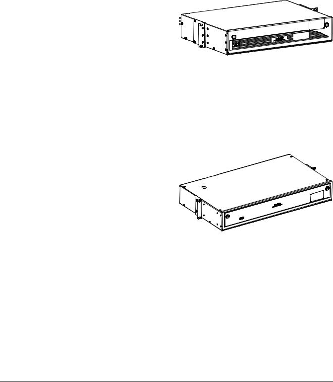
One (1) LMS1000 Expansion Assembly |
|
Features |
|
♦ Provides one (1) LMS1000 EXPANSION ASSEMBLY. |
|
♦ Refer to the "Specifications" section of this document for further information.
Restrictions
The Expansion Assembly analog inputs can only be used for 50mV shunts on the same discharge bus. None of the 24 inputs on any given Expansion Assembly may exceed –0.15 to +0.95 V between inputs. Each of the 8 binary channels are only activated by a -48V signal (typical of a fuse alarm bus).
Ordering Notes
1)Order as required to monitor fixed points outside an Emerson Network Power Power System.
2)Order LMS1000 network cables as required per the "ACCESSORY" section.
3)Also order the following as required to terminate customer wiring to the J18/J19 D-type connectors provided on the assembly.
a)D-Sub Connector Housing (Male): Emerson Network Power P/N 116694 (Tyco P/N 1658641-2).
b)Crimp-Type Pins (Male): Emerson Network Power P/N 245381800 (Tyco P/N 66506-3 [supplied on a strip] or P/N 66506-9 [supplied loose]).
c)Cable Clamp Housing: Emerson Network Power P/N 116731 (Tyco P/N 748677-5).
d)Jack Screw Male Kit: Emerson Network Power P/N 116737 (Tyco P/N 747784-8).
e)Hand Crimping Tool: Pro Crimper II Tyco P/N 58448-2.
List 20: Four (4) Input Analog Circuit Card
Features
♦Monitors voltages, shunts, and current loops.
♦Each circuit card provides four (4) analog inputs to the system.
♦Refer to the "Specifications" section of this document for further information.
Restrictions
Not for use in Expansion Assemblies.
Maximum number of analog points that can be monitored is dependent on how many open I/O slots are available in the system network and maximum number of analog channels the system supports. Each 586505000/586505500 cabinet holds up to ten (10) I/O circuit cards. Refer to "Firmware Specifications" under "Specifications" in this document for number of analog channels supported.
Shunts should be protected by a 49.9 ohm resistor. All other analog inputs should be protected by a fuse in each lead.
Note: When LMS1000 is connected to an MCA, the MCA Interface does not require connections to analog, binary, or relay circuit cards. The MCA Interface provides analog inputs independently from the analog circuit cards installed.
Ordering Notes
1)Order one (1) List 20 analog circuit card for every four (4) analog points to be monitored using LMS1000.
2)Order current limit resistor kits as required per List BA, BB, and BC.
3)Order in-line fuse kits as required per List BE, BF, or P/N 535135.
4)Also available is a 130VDC Monitoring Wire Harness. See ACCESSORY INFORMATION section for description. Order one (1) P/N 520839 130VDC Monitoring Wire Harness per 130VDC input to be monitored, as required.
Page 10 of 62
This document is property of Emerson Network Power, Energy Systems, North America, Inc. and contains confidential and proprietary information owned by Emerson Network Power, Energy Systems, North America, Inc. Any copying, use, or disclosure of it without the written permission of Emerson Network Power, Energy Systems, North America, Inc. is strictly prohibited.
System Application Guide |
SAG586505000 |
Spec. No. 586505000 (Model LMS1000) |
SAG586505500 |
Spec. No. 586505500 (Model LMS1000) |
Issue AZ, April 7, 2014 |
List 21: Eight (8) Input Temperature Circuit Card |
Home |
|
|
Features |
|
♦Monitors temperature probe inputs.
♦Each circuit card provides eight (8) temperature inputs to the system (mapped as analog channels).
♦Refer to the "Specifications" section of this document for further information.
Restrictions
Not for use in Expansion Assemblies.
Maximum number of temperature points that can be monitored is dependent on how many open I/O slots are available in the system network and maximum number of analog channels the system supports. Each 586505000/586505500 cabinet holds up to ten (10) I/O circuit cards. Refer to "Firmware Specifications" under "Specifications" in this document for number of analog channels supported.
Ordering Notes
1)Order one (1) List 21 temperature circuit card for every eight (8) temperature probes to be monitored using LMS1000.
2)Order temperature probes as required per List ST and SU.
List 22: Eight (8) Input Analog Circuit Card
Features
♦Monitors 50 mv shunt inputs.
♦Each circuit card provides eight (8) analog inputs to the system.
♦Refer to the "Specifications" section of this document for further information.
Restrictions
Not for use in Expansion Assemblies.
This circuit card can only be used for 50mV shunts on the same discharge bus. None of the 8 inputs on any given card may exceed –0.15 to +0.95 V between inputs. The card to card voltage differential does not matter. These cards may not be used for RIM applications. For RIM applications, use the universal analog circuit card 586505000 and 586505500 List 20.
Maximum number of analog points that can be monitored is dependent on how many open I/O slots are available in the system network and maximum number of analog channels the system supports. Each 586505000/586505500 cabinet holds up to ten (10) I/O circuit cards. Refer to "Firmware Specifications" under "Specifications" in this document for number of analog channels supported.
Shunt inputs should be protected by a 49.9 ohm resistor.
Note: When LMS1000 is connected to an MCA, the MCA Interface does not require connections to analog, binary, or relay circuit cards. The MCA Interface provides analog inputs independently from the analog circuit cards installed.
Ordering Notes
1)Order one (1) List 22 analog circuit card for every eight (8) analog points to be monitored using LMS1000.
2)Order current limit resistor kits as required per List BA, BB, and BC.
List 23: Twelve (12) Input Analog Circuit Card for Measuring Individual Battery Cell Voltages
Features
♦Monitors individual battery cell voltages.
♦Each circuit card provides twelve (12) analog inputs to the system.
♦Refer to the "Specifications" section of this document for further information.
Page 11 of 62
This document is property of Emerson Network Power, Energy Systems, North America, Inc. and contains confidential and proprietary information owned by Emerson Network Power, Energy Systems, North America, Inc. Any copying, use, or disclosure of it without the written permission of Emerson Network Power, Energy Systems, North America, Inc. is strictly prohibited.

SAG586505000 |
System Application Guide |
|
SAG586505500 |
Spec. No. 586505000 (Model LMS1000) |
|
Issue AZ, April 7, 2014 |
Spec. No. 586505500 (Model LMS1000) |
|
Restrictions |
|
Home |
|
|
|
Not for use in Expansion Cabinets and Expansion Assemblies. |
|
|
This circuit card must only be used for adjacent cells in a common battery string. The input requires the intercell connector to be the negative (–) input on one cell and the positive (+) input for the next one. This cannot be used for pilot cells in multiple battery strings.
A maximum of six (6) cards may be installed in the Main Cabinet
Maximum number of analog points that can be monitored is dependent on how many open I/O slots are available in the system network and maximum number of analog channels the system supports. Each 586505000/586505500 cabinet holds up to ten (10) I/O circuit cards. Refer to "Firmware Specifications" under "Specifications" in this document for number of analog channels supported.
Analog inputs should be protected by a fuse in each lead.
Ordering Notes
1)Order one (1) List 23 analog circuit card for every twelve (12) battery cells to be monitored using LMS1000.
2)Order in-line fuse kits as required per List BE, BF, or P/N 535135.
List 30: Four (4) Input Binary Circuit Card
Features
♦Monitors 0-60 volts AC/DC double ended binary inputs.
♦Each circuit card provides four (4) binary inputs to the system. Each input requires two connections (source and return).
♦Refer to the "Specifications" section of this document for further information.
Restrictions
Not for use in Expansion Assemblies.
Maximum number of binary points that can be monitored is dependent on how many open I/O slots are available in the system network and maximum number of binary channels the system supports. Each 586505000/586505500 cabinet holds up to ten (10) I/O circuit cards. Refer to "Firmware Specifications" under "Specifications" in this document for number of binary channels supported.
Note: When LMS1000 is connected to an MCA, the MCA Interface does not require connections to analog, binary, or relay circuit cards. The MCA Interface provides binary inputs independently from the binary circuit cards installed.
Ordering Notes
1)Order one (1) List 30 binary circuit card for every four (4) binary points to be monitored using LMS1000.
2)For recommended protection on input wiring, order current limit resistor kits as required per List BA, BB, and BC.
List 31: Eight (8) Input Binary Circuit Card
Features
♦Monitors 0-60 volts AC/DC single ended inputs.
♦Each circuit card provides eight (8) binary inputs to the system. Each input requires only one connection (source), plus a single +BAT and/or -BAT connection for all inputs as required.
♦The other connection point for each binary input is made via the placement of the appropriate jumper on the circuit card. This jumper either applies +BAT or -BAT to this connection point. This simplifies wiring to the binary inputs since +BAT and/or -BAT, as required, only has to be connected to the circuit card at one point.
♦Refer to the "Specifications" section of this document for further information.
Page 12 of 62
This document is property of Emerson Network Power, Energy Systems, North America, Inc. and contains confidential and proprietary information owned by Emerson Network Power, Energy Systems, North America, Inc. Any copying, use, or disclosure of it without the written permission of Emerson Network Power, Energy Systems, North America, Inc. is strictly prohibited.

System Application Guide |
SAG586505000 |
|
Spec. No. 586505000 (Model LMS1000) |
SAG586505500 |
|
Spec. No. 586505500 (Model LMS1000) |
Issue AZ, April 7, 2014 |
|
Restrictions |
|
Home |
|
|
|
Not for use in Expansion Assemblies. |
|
|
Maximum number of binary points that can be monitored is dependent on how many open I/O slots are available in the system network and maximum number of binary channels the system supports. Each 586505000/586505500 cabinet holds up to ten (10) I/O circuit cards. Refer to "Firmware Specifications" under "Specifications" in this document for number of binary channels supported.
Note: When LMS1000 is connected to an MCA, the MCA Interface does not require connections to analog, binary, or relay circuit cards. The MCA Interface provides binary inputs independently from the binary circuit cards installed.
Ordering Notes
1)Order one (1) List 31 binary circuit card for every eight (8) binary points to be monitored using LMS1000.
2)For recommended protection on input wiring, order current limit resistor kits as required per List BA, BB, and BC.
List 40: Four (4) Output Form-C Relay Circuit Card
Features
♦Provides four relays each with one set of Form-C relay contacts.
♦These relays are used for control or alarm applications and can be programmed by the user.
♦Relays may also be manually forced "on" (energized) (SET RLY). Any relay forced on can also be manually turned off (CLR RLY). (A jumper is provided on the relay circuit card to enable/disable the SET RLY and CLR RLY commands.)
♦The relay circuit cards can also be programmed to work with the energy management and/or sequential start option, if ordered (relays are not required to provide energy management and/or sequential start to a VPS/NPS Power System).
♦Refer to the "Specifications" section of this document for further information.
Restrictions
Not for use in Expansion Assemblies.
Maximum number of relay outputs that can be provided is dependent on how many open I/O slots are available in the system network and maximum number of rely channels the system supports. Each 586505000/586505500 cabinet holds up to ten (10) I/O circuit cards. Refer to "Firmware Specifications" under "Specifications" in this document for number of relay channels supported.
Note: When LMS1000 is connected to an MCA, the MCA Interface does not require connections to analog, binary, or relay circuit cards. When energy management and/or sequencing option is ordered, relays are not required to control the VPS/NPS PCUs.
Note: Also available in a Spec. No. 582140000, 582140001, and 582126100 Power System are MCA Customer Alarm Relay circuit cards. Refer to SAG582140000, SAG582140001, and SAG582126100.
Ordering Notes
1) Order one (1) List 40 relay circuit card for every four (4) relay contacts to be provided by LMS1000.
List 60: LMS1000 Display Option (for use in later version 586505000 19" cabinets) Features
♦Provides a front panel display and keypad.
♦Allows local access to the system without a terminal.
♦You can view plant voltage and load current, view active alarms, perform channel scans, view the Events Log and Alarm Log, view channel statistics, and view battery discharge history.
Restrictions
Page 13 of 62
This document is property of Emerson Network Power, Energy Systems, North America, Inc. and contains confidential and proprietary information owned by Emerson Network Power, Energy Systems, North America, Inc. Any copying, use, or disclosure of it without the written permission of Emerson Network Power, Energy Systems, North America, Inc. is strictly prohibited.

SAG586505000 |
System Application Guide |
|
SAG586505500 |
Spec. No. 586505000 (Model LMS1000) |
|
Issue AZ, April 7, 2014 |
Spec. No. 586505500 (Model LMS1000) |
|
There are two kits offered for the 19" cabinet. One kit is used with the earlier version cabinet, the |
Home |
|
|
||
other for the later version cabinet. |
|
|
586505000 List 1 cabinets manufactured on or before 3/21/03, use kit P/N 524354 (586505000 List 61). 586505000 List 1 cabinets manufactured after 3/21/03, use kit P/N 524353 (586505000 List 60).
The later version cabinet has been modified to allow the LMS1000 Display Interface circuit card to be plugged into the 10th LMS1000 I/O circuit card mounting slot. To determine exactly which kit is compatible with your 19" cabinet, look at the LMS1000 I/O circuit card backplane connectors. If all backplane connectors are uniform, you have the earlier version cabinet and must use kit P/N 524354 (586505000 List 61). If the 10th I/O backplane connector is longer then the others, you have a later version cabinet that uses Kit P/N 524353 (586505000 List 60). See the following illustration.
Requires the right-most I/O circuit card mounting slot. Requires LMS1000 firmware 5.0.0 or later.
Requires use of the LMS1000 OEM2 Port. CANNOT be used if List 84 ordered. Not for use in 23" cabinets.
Not for use in Spec. Nos. 582140000, 582140001, and 582126100 Power Systems.
|
|
|
|
|
|
|
|
|
|
|
|
|
|
|
|
|
|
|
|
|
|
|
|
|
|
|
|
|
|
|
|
|
|
|
|
|
|
|
|
|
|
|
|
|
|
|
|
|
|
|
|
|
|
|
|
|
|
|
|
|
|
|
|
|
|
|
|
|
|
|
|
|
|
|
|
|
|
|
|
|
|
|
|
|
|
|
|
|
|
|
|
|
|
|
|
|
|
|
|
|
|
|
|
|
|
|
|
|
|
|
|
|
|
|
|
|
|
|
|
|
|
|
|
|
|
|
|
|
|
|
|
|
|
|
|
|
|
|
|
|
|
|
|
|
|
|
|
|
|
|
|
|
|
|
|
|
|
|
|
|
|
|
|
|
|
|
|
|
|
|
|
|
|
|
|
|
|
|
|
|
|
|
|
|
|
|
|
|
|
|
|
|
|
|
|
|
|
|
|
|
|
|
|
|
|
|
|
|
|
|
|
|
|
|
|
|
|
|
|
|
|
|
|
|
|
|
|
|
|
|
|
|
|
|
|
|
|
|
|
|
|
|
|
|
|
|
|
|
|
|
|
|
|
|
|
|
|
|
|
|
|
|
|
|
|
|
|
|
|
|
|
|
|
|
|
|
|
|
|
|
|
|
|
|
|
|
|
|
|
|
|
|
|
|
|
|
|
|
|
|
|
|
|
|
|
|
|
|
|
|
|
|
|
|
|
|
|
|
|
|
|
|
|
|
|
|
|
|
|
|
|
|
|
|
|
|
|
|
|
|
|
|
|
|
|
|
|
|
|
|
|
|
|
|
|
|
|
|
|
|
|
|
|
|
|
|
|
|
|
|
|
|
|
|
|
|
|
|
|
|
|
|
|
|
|
|
|
|
|
|
|
|
|
|
|
|
|
|
|
|
|
|
|
|
|
|
|
|
|
|
|
|
|
|
|
|
|
|
|
|
|
|
|
|
|
|
|
|
|
|
|
|
|
|
|
|
|
|
|
|
|
|
|
|
|
|
|
|
Front Door |
||||||||||||||
|
|
|
|
|
|
|
|
|
|
|
|
|
|
|
|
|
|
|
|
|
|
|
|
|
|
|
|
|
|
|
|
|
|
|
|
|
|
|
|
|
|
|
|
|
|
|
|
|
|
|
|
|
|
|
|
|
|
|
|
|
|
|
|
|
|
|
|
|
|
|
|
|
|
|
|
|
|
|
|
|
|
|
|
|
|
|
|
|
|
|
|
|
|
|
|
|
|
|
|
|
Opened in |
||||||||||||||
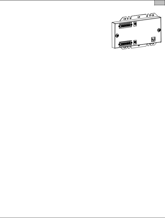
Determines earlier version vs. later version 19" cabinet. |
|
|
|
|
Illustration |
||||||||||||||||||||||||||||||||||||||||||||||||||||||||||||||||||||||||||||||||||||||||||||||||||||||||||||||
Earlier Version Cabinet: I/O slot #10 is the same as the other I/O slots.
USE KIT P/N 524354 (586505000 List 61)
Later Version Cabinet: I/O Slot #10 has a larger (30 pos.) connector. USE KIT P/N 524353 (586505000 List 60)
Ordering Notes
1)Order one (1) List 60 to provide a front panel display and keypad in a later version 586505000 19" cabinets. This option is factory installed if ordered with the system. This option is also field installable.
List 61: LMS1000 Display Option (for use in earlier version 586505000 19" cabinets) Features
♦Provides a front panel display and keypad.
♦Allows local access to the system without a terminal.
♦You can view plant voltage and load current, view active alarms, perform channel scans, view the Events Log and Alarm Log, view channel statistics, and view battery discharge history.
Restrictions
There are two kits offered for the 19" cabinet. One kit is used with the earlier version cabinet, the other for the later version cabinet.
586505000 List 1 cabinets manufactured on or before 3/21/03, use kit P/N 524354 (586505000 List 61). 586505000 List 1 cabinets manufactured after 3/21/03, use kit P/N 524353 (586505000 List 60).
The later version cabinet has been modified to allow the LMS1000 Display Interface circuit card to be plugged into the 10th LMS1000 I/O circuit card mounting slot. To determine exactly which kit is compatible with your 19" cabinet, look at the LMS1000 I/O circuit card backplane connectors. If all backplane connectors are
Page 14 of 62
This document is property of Emerson Network Power, Energy Systems, North America, Inc. and contains confidential and proprietary information owned by Emerson Network Power, Energy Systems, North America, Inc. Any copying, use, or disclosure of it without the written permission of Emerson Network Power, Energy Systems, North America, Inc. is strictly prohibited.

System Application Guide |
SAG586505000 |
|
Spec. No. 586505000 (Model LMS1000) |
SAG586505500 |
|
Spec. No. 586505500 (Model LMS1000) |
Issue AZ, April 7, 2014 |
|
uniform, you have the earlier version cabinet and must use kit P/N 524354 (586505000 List 61). If |
Home |
|
|
||
the 10th I/O backplane connector is longer then the others, you have a later version cabinet that uses |
|
|
Kit P/N 524353 (586505000 List 60). See the above illustration. |
|
|
Requires LMS1000 firmware 5.0.0 or later. |
|
|
Requires use of the LMS1000 OEM2 Port. CANNOT be used if List 84 ordered. |
|
|
Not for use in 23" cabinets. |
|
|
Not for use in Spec. Nos. 582140000, 582140001, and 582126100 Power Systems. |
|
|
Ordering Notes
1)Order one (1) List 61 to provide a front panel display and keypad in an earlier version 586505000 19" cabinets. This option is field installable.
List 62: LMS1000 Display Option (for use in 586505000/586505500 23" cabinets) Features
♦Provides a front panel display and keypad.
♦Allows local access to the system without a terminal.
♦You can view plant voltage and load current, view active alarms, perform channel scans, view the Events Log and Alarm Log, view channel statistics, and view battery discharge history.
Restrictions
Requires the right-most I/O circuit card mounting slot
(see List 63 for a kit that DOES NOT require the right-most I/O slot). Requires LMS1000 firmware 5.0.0 or later.
Requires use of the LMS1000 OEM2 Port. CANNOT be used if List 84 ordered. Not for use in 19" cabinets.
Not for use in Spec. Nos. 582140000, 582140001, and 582126100 Power Systems.
Ordering Notes
1)Order one (1) List 62 to provide a front panel display and keypad in a 23" cabinet. This option is factory installed if ordered with the system. This option is also field installable.
586505000 List 62 provides a new 23" off-white front panel. 586505500 List 62 provides a new 23" gray front panel.
List 63: LMS1000 Display Option (for use in 586505000/586505500 23" cabinets) Features
♦Provides a front panel display and keypad.
♦Allows local access to the system without a terminal.
♦You can view plant voltage and load current, view active alarms, perform channel scans, view the Events Log and Alarm Log, view channel statistics, and view battery discharge history.
♦Similar to List 61 that DOES NOT require the use of the 10th I/O slot.
Restrictions
Requires LMS1000 firmware 5.0.0 or later.
Requires use of the LMS1000 OEM2 Port. CANNOT be used if List 84 ordered.
Not for use in 19" cabinets.
Not for use in Spec. Nos. 582140000, 582140001, and 582126100 Power Systems.
Ordering Notes
1)Order one (1) List 63 to provide a front panel display and keypad in a 23" cabinet. This option is factory installed if ordered with the system. This option is also field installable.
Page 15 of 62
This document is property of Emerson Network Power, Energy Systems, North America, Inc. and contains confidential and proprietary information owned by Emerson Network Power, Energy Systems, North America, Inc. Any copying, use, or disclosure of it without the written permission of Emerson Network Power, Energy Systems, North America, Inc. is strictly prohibited.

SAG586505000 |
|
System Application Guide |
|
SAG586505500 |
|
Spec. No. 586505000 (Model LMS1000) |
|
Issue AZ, April 7, 2014 |
Spec. No. 586505500 (Model LMS1000) |
||
586505000 |
List 63 provides a new 23" off-white front panel. |
|
Home |
|
|
||
586505500 |
List 63 provides a new 23" gray front panel. |
|
|
List 70: Modem Circuit Card
Features
♦Provides for remote communications up to 56K BPS.
♦An RJ-11 jack (for telephone line connection) is provided on the rear of the 586505000/586505500 cabinet. In a Spec. No. 582140000, 582140001, and 582126100 Power System; the RJ-11 jack located on the circuit card is used.
♦Plugs onto the Main CPU circuit card.
♦Refer to the "Specifications" section of this document for further information.
Restrictions
For use in a 586505000/586505500 Main Cabinet or 582140000/582140001/582126100 Primary Bay only.
Required for remote terminal or pager alarm notification via the System Alarm Reporting and/or Individual User Alarm Reporting mechanisms.
Ordering Notes
1)Order a List 70 modem circuit card if remote communications and/or alarm reporting over a telephone line is required.
List 78: LMS Dual MCA Interface Software Option
Features
♦Allows the MCA in a Spec. No. 582140000, 582140001, or 582126100 NETSURE Power System (NPS) to interface with the MCA in a Vortex Power System (VPS) via the LMS.
♦Refer to the "Specifications" section of this document for further information.
Restrictions
Can only be used in the integrated LMS of a Spec. Nos. 582140000, 582140001, and 582126100 systems. Operation of Energy Management is disabled when the Dual MCA Interface option is installed.
Ordering Notes
1)Order List 78 if a 582140000, 582140001, or 582126100 system is to interface with an MCA in a Vortex Power System (VPS) via the LMS.
List 79: Gateway Port Software Option
Features
♦Allows the LMS1000 to emulate a “dumb” RS-232 asynchronous terminal interface. When installed, user input through either a local or remote LMS1000 port is directed to the customer equipment connected to the LMS1000 Gateway port.
♦When connected to a Lorain SMART DGU, automatically extends some LMS commands to the DGU and returns DGU responses to user port.
♦Refer to the "Specifications" section of this document for further information.
Restrictions
In the 586505000/586505500 system, the Gateway port is provided via the LMS1000 OEM1 port. CANNOT be used if List 85, List 86, or List 88 ordered.
In the Spec. Nos. 582140000, 582140001, and 582126100 Power Systems; the Gateway port is provided via the port located on the front of the LMS1000 CPU circuit card installed in the Primary Bay.
Refer to the "Specifications" section of this document for further restrictions.
Page 16 of 62
This document is property of Emerson Network Power, Energy Systems, North America, Inc. and contains confidential and proprietary information owned by Emerson Network Power, Energy Systems, North America, Inc. Any copying, use, or disclosure of it without the written permission of Emerson Network Power, Energy Systems, North America, Inc. is strictly prohibited.

System Application Guide |
SAG586505000 |
|
Spec. No. 586505000 (Model LMS1000) |
SAG586505500 |
|
Spec. No. 586505500 (Model LMS1000) |
Issue AZ, April 7, 2014 |
|
Ordering Notes |
|
Home |
|
|
|
1)Order List 79 if a Gateway Port is required.
2)If you are connecting the Gateway Port to a DGU, also order null modem cable P/N 545562 (5’) or 548010 (50’). This cable connects between the DGU and the LMS1000.
3)In Power Systems with an integrated controller shelf [NetSure 702, NetSure 801, NetSure 802], connecting the Gateway Port to a DGU requires a straight through cable P/N 548009 be ordered. This cable connects between the DGU COM1 card, Port A, and the LMS RS-232 port located on the front of the LMS card assembly.
List 80: Door Access Controller (DAC) Interface
Features
♦Configure and monitor the Door Access Controller via LMS1000.
♦Refer to the "Specifications" section of this document for further information.
Restrictions
Interfaces to a Desarrollos Digitales Door Access Controller Model MKC-1 only.
The DAC Port is provided via the OEM3 (VPS/NPS) Port. If used with a VPS/NPS, customer must provide a "Y" cable to allow both the Door Access Controller and VPS/NPS to be connected to the LMS1000 OEM3 Port.
Recommended to use a Desarrollos Digitales Isolation Board (Model DTP-1-485 / 96-DC24-T, E) between the DAC and LMS1000.
Not for use in Spec. Nos. 582140000, 582140001, and 582126100 Power Systems.
Ordering Notes
1) Order List 80 as required.
List 82: PCU/Rectifier Sequencing Software Option
Features
♦Provides PCU/Rectifier Sequential Start.
♦Refer to the "Specifications" section of this document for further information.
Restrictions
Besides the sequencing software option, LMS1000 requires dedicated binary (VPS/NPS and traditional rectifiers) and relay (traditional rectifiers only) inputs/outputs to manage the power plant. See the Wiring section of the Installation Instructions (Section 5879).
The LMS1000 Sequencing feature is not for use in 582140000, 582140001, and 582126100 Power Systems.
Ordering Notes
1)Order List 82 if PCU/Rectifier Sequencing is required.
2)Order a binary circuit card if spare inputs are not available for a Commercial AC Fail/Transfer Detection input and a Standby On/Proper Operate Detection input. (Binary channel 9011 'All AC Off' may be used as the Commercial AC Fail/Transfer Detection input in a VPS/NPS Power System).
3)Order analog, binary, and relay circuit cards as required when used with 'traditional rectifiers'.
List 83: Energy Management Software Option
Features
♦Provides PCU/Rectifier Energy Management
♦Refer to the "Specifications" section of this document for further information.
Page 17 of 62
This document is property of Emerson Network Power, Energy Systems, North America, Inc. and contains confidential and proprietary information owned by Emerson Network Power, Energy Systems, North America, Inc. Any copying, use, or disclosure of it without the written permission of Emerson Network Power, Energy Systems, North America, Inc. is strictly prohibited.

SAG586505000 |
System Application Guide |
SAG586505500 |
Spec. No. 586505000 (Model LMS1000) |
Issue AZ, April 7, 2014 |
Spec. No. 586505500 (Model LMS1000) |
Restrictions |
Home |
|
Besides the energy management software option, LMS1000 requires dedicated analog, binary, and relay (traditional rectifiers only) inputs/outputs to manage the power plant. See the Wiring section of the Installation Instructions (Section 5879).
The LMS1000 Energy Management feature is not for use in Spec. Nos. 582140000, 582140001, and 582126100 Power Systems.
Ordering Notes
1)Order List 83 if PCU/Rectifier Energy Management is required.
2)Order analog, binary, and relay circuit cards as required when used with 'traditional rectifiers'.
List 84: External GPS Modem Interface
Features
♦Provides access to the LMS1000 via an external GPS Modem.
♦Refer to the "Specifications" section of this document for further information.
Restrictions
Interfaces to an Enfora GPS External Modem only.
External Modem Port is provided via the LMS1000 OEM2 Port. CANNOT be used if List 60, 61, 62, or 63 ordered.
Not for use in Spec. Nos. 582140000, 582140001, and 582126100 Power Systems.
Ordering Notes
1) Order List 84 as required.
List 85: AC Analyzer Interface
Features
♦LMS1000 reads and records values from the AC Analyzer.
♦Refer to the "Specifications" section of this document for further information.
Restrictions
Interfaces to a Dossena AC Analyzer Model MV3DL only.
AC Analyzer Port is provided via the LMS1000 OEM1 Port. CANNOT be used if List 79, List 86, or List 88 ordered.
Not for use in Spec. Nos. 582140000, 582140001, and 582126100 Power Systems.
Ordering Notes
1) Order List 85 as required.
List 86: TL1/X.25 Software Option
Features
♦Provides a TL1/X.25 Interface and RS-232 Port with PAD support.
♦Refer to the "Specifications" section of this document for further information.
Restrictions
TL1/X.25 Port is provided via the LMS1000 OEM1 Port. CANNOT be used if List 79, List 85, List 88, or List 90 ordered.
Not for use in Spec. Nos. 582140000, 582140001, and 582126100 Power Systems.
Ordering Notes
1) Order List 86 if TL1/X.25 is required (see also List 90 for another TL1 option).
Page 18 of 62
This document is property of Emerson Network Power, Energy Systems, North America, Inc. and contains confidential and proprietary information owned by Emerson Network Power, Energy Systems, North America, Inc. Any copying, use, or disclosure of it without the written permission of Emerson Network Power, Energy Systems, North America, Inc. is strictly prohibited.

System Application Guide |
SAG586505000 |
|
Spec. No. 586505000 (Model LMS1000) |
SAG586505500 |
|
Spec. No. 586505500 (Model LMS1000) |
Issue AZ, April 7, 2014 |
|
List 87: Power Metering Software Option |
|
Home |
|
|
|
Features |
|
|
♦ Refer to the "Specifications" section of this document for further information. |
|
|
Restrictions |
|
|
This option must be factory installed, or field installed by Emerson Network Power only. This option can be field installed remotely via dial-up phone lines if your LMS1000 is equipped with a modem or via Ethernet if connected to a TCP/IP network.
Ordering Notes
1)Order List 87 if Power Metering is required.
2)Order a List 20 analog circuit card. This analog circuit card provides 4 analog inputs. One will be connected to system voltage. This leaves three for measuring customer loads. Order one additional analog circuit card per four additional customer loads to be monitored. Note that there is also an 8-input analog circuit card (List 22) available which monitors up to eight 50 mv shunts.
3)Also order one (1) in-line fuse kit to protect the analog leads connected to system voltage. Specify List BE (3/8” ring lug), List BF (5/16” ring lug), or P/N 535135 (1/4” ring lug, 3/8” ring lug, or butt splice).
4)And order a current limit resistor kit for each customer load to be monitored for power consumption. Specify List BA (3/8” ring lug), List BB (splice), or List BC (ring lug for #10 stud)
List 88: Local Port Redirection to OEM 1 Port Option Features
♦ Local communications access is provided via the rear OEM 1 port instead of the front panel port.
Restrictions
The local port is redirected to the LMS1000 OEM1 Port. CANNOT be used if List 79, List 85, or List 86 ordered.
Not for use in Spec. Nos. 582140000, 582140001, and 582126100 Power Systems.
Ordering Notes
1) Order List 88 if the local port is required to be on the rear of the cabinet instead of on the front.
List 90: TL1 (over Ethernet) Software Option
Features
♦With the TL1 (over Ethernet) software option, LMS1000 supports TL1 interface in a TCP/IP network. An Ethernet port is provided for this network connection.
♦Refer to the "Specifications" section of this document for further information.
Restrictions
CANNOT be used if List 86 is ordered.
Ordering Notes
1) Order List 90 if TL1 (over Ethernet) is required (see also List 86 for another TL1 option).
List 92: MCA Interface Cable, Customer Specified Length
Features
♦A category 5, four twisted pair conductor, 24 AWG solid copper cable.
♦Cable connects between the MCA of a Vortex Power System (VPS) or NETSURE Power System (NPS) and the 586505000/586505500 Main Cabinet.
♦Customer specified length cable.
♦See also List 94.
Page 19 of 62
This document is property of Emerson Network Power, Energy Systems, North America, Inc. and contains confidential and proprietary information owned by Emerson Network Power, Energy Systems, North America, Inc. Any copying, use, or disclosure of it without the written permission of Emerson Network Power, Energy Systems, North America, Inc. is strictly prohibited.
Loading...