


 Loading...


 Liebert® iCOM®


 User Manual -Intelligent Communications & Monitoring for Liebert Challenger 3000™,


 Liebert CW™ and Liebert DS™ with Software Version PA2.01.48R


TABLE OF CONTENTS
1.0 INTRODUCTION . . . . . . . . . . . . . . . . . . . . . . . . . . . . . . . . . . . . . . . . . . . . . . . . . . . . . . . . . .1
1.1 Features . . . . . . . . . . . . . . . . . . . . . . . . . . . . . . . . . . . . . . . . . . . . . . . . . . . . . . . . . . . . . . . . . . . 1
2.0 LIEBERT ICOM DISPLAY COMPONENTS AND FUNCTIONS . . . . . . . . . . . . . . . . . . . . . . . . . . .2
2.1 Control Interface—Large Display . . . . . . . . . . . . . . . . . . . . . . . . . . . . . . . . . . . . . . . . . . . . . . . 4
2.1.1 Navigating to Various Views in the Liebert iCOM. . . . . . . . . . . . . . . . . . . . . . . . . . . . . . . . . . . 5
2.2 System Screen. . . . . . . . . . . . . . . . . . . . . . . . . . . . . . . . . . . . . . . . . . . . . . . . . . . . . . . . . . . . . . . 6 2.3 Unit View with Rack Sensors . . . . . . . . . . . . . . . . . . . . . . . . . . . . . . . . . . . . . . . . . . . . . . . . . . 8 2.4 Navigating Through the Liebert iCOM Menus . . . . . . . . . . . . . . . . . . . . . . . . . . . . . . . . . . . . 8
2.4.1 Accessing Submenus on Large Displays . . . . . . . . . . . . . . . . . . . . . . . . . . . . . . . . . . . . . . . . . . . 9 2.4.2 Accessing Submenus on Small Displays . . . . . . . . . . . . . . . . . . . . . . . . . . . . . . . . . . . . . . . . . . 11
2.5 Display Setup . . . . . . . . . . . . . . . . . . . . . . . . . . . . . . . . . . . . . . . . . . . . . . . . . . . . . . . . . . . . . . 12
2.5.1 Entering a Password . . . . . . . . . . . . . . . . . . . . . . . . . . . . . . . . . . . . . . . . . . . . . . . . . . . . . . . . . 12 2.5.2 Viewing Multiple Units with a Networked Large Display. . . . . . . . . . . . . . . . . . . . . . . . . . . . 13
3.0 OPERATION . . . . . . . . . . . . . . . . . . . . . . . . . . . . . . . . . . . . . . . . . . . . . . . . . . . . . . . . . . .18
3.1 Single Unit Functions . . . . . . . . . . . . . . . . . . . . . . . . . . . . . . . . . . . . . . . . . . . . . . . . . . . . . . . 18
3.1.1 |
Unit/Fan Control . . . . . . . . . . . . . . . . . . . . . . . . . . . . . . . . . . . . . . . . . . . . . . . . . . . . . . . . . . . . |
18 |
3.1.2 Back-Draft Fan Damper—Units with EC Fans . . . . . . . . . . . . . . . . . . . . . . . . . . . . . . . . . . . . |
22 |
|
3.1.3 Back-Draft Fan Damper—Units with Centrifugal Fans . . . . . . . . . . . . . . . . . . . . . . . . . . . . . |
23 |
|
3.1.4 |
Power Monitoring . . . . . . . . . . . . . . . . . . . . . . . . . . . . . . . . . . . . . . . . . . . . . . . . . . . . . . . . . . . . |
23 |
3.1.5 |
General Compressor Operation . . . . . . . . . . . . . . . . . . . . . . . . . . . . . . . . . . . . . . . . . . . . . . . . . |
23 |
3.1.6 |
Compressor Timing—Short-Cycle Protection . . . . . . . . . . . . . . . . . . . . . . . . . . . . . . . . . . . . . . |
25 |
3.1.7 |
Compressor Sequencing on Two-Compressor Units . . . . . . . . . . . . . . . . . . . . . . . . . . . . . . . . . |
26 |
3.1.8 |
Motorized Ball Valve in Water-Cooled Units . . . . . . . . . . . . . . . . . . . . . . . . . . . . . . . . . . . . . . |
26 |
3.1.9 |
MBV Operation After Compressor is Turned Off . . . . . . . . . . . . . . . . . . . . . . . . . . . . . . . . . . . |
26 |
3.1.10 |
Service Offset—Changing System Pressure Settings . . . . . . . . . . . . . . . . . . . . . . . . . . . . . . . |
27 |
3.2 General Chilled Water Operation . . . . . . . . . . . . . . . . . . . . . . . . . . . . . . . . . . . . . . . . . . . . . . 27
3.2.1 Chilled Water Quick Start . . . . . . . . . . . . . . . . . . . . . . . . . . . . . . . . . . . . . . . . . . . . . . . . . . . . . 27 3.2.2 Improved Valve Response . . . . . . . . . . . . . . . . . . . . . . . . . . . . . . . . . . . . . . . . . . . . . . . . . . . . . 27 3.2.3 Custom Dual Chilled Water Valve Staging . . . . . . . . . . . . . . . . . . . . . . . . . . . . . . . . . . . . . . . 28 3.2.4 Fluid Temperature Monitoring . . . . . . . . . . . . . . . . . . . . . . . . . . . . . . . . . . . . . . . . . . . . . . . . . 29 3.2.5 Fluid Flow Monitoring . . . . . . . . . . . . . . . . . . . . . . . . . . . . . . . . . . . . . . . . . . . . . . . . . . . . . . . . 29
3.3 Temperature Control . . . . . . . . . . . . . . . . . . . . . . . . . . . . . . . . . . . . . . . . . . . . . . . . . . . . . . . . 29
3.3.1 Setting Up PI Control. . . . . . . . . . . . . . . . . . . . . . . . . . . . . . . . . . . . . . . . . . . . . . . . . . . . . . . . . 31 3.3.2 Compressor Control . . . . . . . . . . . . . . . . . . . . . . . . . . . . . . . . . . . . . . . . . . . . . . . . . . . . . . . . . . 32 3.3.3 Chilled Water Control . . . . . . . . . . . . . . . . . . . . . . . . . . . . . . . . . . . . . . . . . . . . . . . . . . . . . . . . 35
3.4 Liebert Fluid Economizer. . . . . . . . . . . . . . . . . . . . . . . . . . . . . . . . . . . . . . . . . . . . . . . . . . . . . 35
3.4.1 Differential Temperatures / Controls (Comparator Circuit) . . . . . . . . . . . . . . . . . . . . . . . . . . 36 3.4.2 Liebert Air Economizer™ . . . . . . . . . . . . . . . . . . . . . . . . . . . . . . . . . . . . . . . . . . . . . . . . . . . . . . 38
3.5 Liebert Air Economizer™ Operation . . . . . . . . . . . . . . . . . . . . . . . . . . . . . . . . . . . . . . . . . . . . 41
3.5.1 Liebert Air Economizer™ System Overview . . . . . . . . . . . . . . . . . . . . . . . . . . . . . . . . . . . . . . . 42 3.5.2 Liebert Air Economizer Control Settings . . . . . . . . . . . . . . . . . . . . . . . . . . . . . . . . . . . . . . . . . 44 3.5.3 Disable the Liebert Air Economizer . . . . . . . . . . . . . . . . . . . . . . . . . . . . . . . . . . . . . . . . . . . . . 47 3.5.4 Adjust the Restricted Airflow Switch on the Liebert Air Economizer. . . . . . . . . . . . . . . . . . . 48
i

3.6 Temperature Control—Reheat . . . . . . . . . . . . . . . . . . . . . . . . . . . . . . . . . . . . . . . . . . . . . . . . 48
3.6.1 Electric, Hot Gas and Hot Water Reheat . . . . . . . . . . . . . . . . . . . . . . . . . . . . . . . . . . . . . . . . . 49
3.6.2 SCR Reheat. . . . . . . . . . . . . . . . . . . . . . . . . . . . . . . . . . . . . . . . . . . . . . . . . . . . . . . . . . . . . . . . . 50
3.7 Humidity Control . . . . . . . . . . . . . . . . . . . . . . . . . . . . . . . . . . . . . . . . . . . . . . . . . . . . . . . . . . . 51
3.7.1 Humidification . . . . . . . . . . . . . . . . . . . . . . . . . . . . . . . . . . . . . . . . . . . . . . . . . . . . . . . . . . . . . . 54
3.7.2 Dehumidification . . . . . . . . . . . . . . . . . . . . . . . . . . . . . . . . . . . . . . . . . . . . . . . . . . . . . . . . . . . . 54
3.8 Supply Control . . . . . . . . . . . . . . . . . . . . . . . . . . . . . . . . . . . . . . . . . . . . . . . . . . . . . . . . . . . . . 58
3.9 Liebert Optimized Aisle Control . . . . . . . . . . . . . . . . . . . . . . . . . . . . . . . . . . . . . . . . . . . . . . . 59
3.9.1 Operation . . . . . . . . . . . . . . . . . . . . . . . . . . . . . . . . . . . . . . . . . . . . . . . . . . . . . . . . . . . . . . . . . . 60
3.9.2 Static Pressure Control . . . . . . . . . . . . . . . . . . . . . . . . . . . . . . . . . . . . . . . . . . . . . . . . . . . . . . . 65
3.10 Event Types and Properties. . . . . . . . . . . . . . . . . . . . . . . . . . . . . . . . . . . . . . . . . . . . . . . . . . . 68
3.10.1 Highand Low-Temperature and Humidity Events . . . . . . . . . . . . . . . . . . . . . . . . . . . . . . . . |
70 |
|
3.10.2 |
User Inputs . . . . . . . . . . . . . . . . . . . . . . . . . . . . . . . . . . . . . . . . . . . . . . . . . . . . . . . . . . . . . . . . . |
71 |
3.10.3 |
Analog Inputs . . . . . . . . . . . . . . . . . . . . . . . . . . . . . . . . . . . . . . . . . . . . . . . . . . . . . . . . . . . . . . . |
72 |
3.10.4 |
Liebert iCOM-DO™ . . . . . . . . . . . . . . . . . . . . . . . . . . . . . . . . . . . . . . . . . . . . . . . . . . . . . . . . . . |
73 |
3.10.5 |
Possible Event Notifications . . . . . . . . . . . . . . . . . . . . . . . . . . . . . . . . . . . . . . . . . . . . . . . . . . . |
74 |
3.11 Wellness—Next Maintenance Calculation . . . . . . . . . . . . . . . . . . . . . . . . . . . . . . . . . . . . . . . 75
3.11.1 Calculating Next Maintenance and Diagnostics . . . . . . . . . . . . . . . . . . . . . . . . . . . . . . . . . . . |
75 |
4.0 TEAMWORK . . . . . . . . . . . . . . . . . . . . . . . . . . . . . . . . . . . . . . . . . . . . . . . . . . . . . . . . . . .77
4.1 Compatibility With Previous Liebert iCOM Controls . . . . . . . . . . . . . . . . . . . . . . . . . . . . . . 77 4.2 Teamwork Modes . . . . . . . . . . . . . . . . . . . . . . . . . . . . . . . . . . . . . . . . . . . . . . . . . . . . . . . . . . . 77
4.2.1 Application of Teamwork Modes . . . . . . . . . . . . . . . . . . . . . . . . . . . . . . . . . . . . . . . . . . . . . . . . 78 4.2.2 No Teamwork . . . . . . . . . . . . . . . . . . . . . . . . . . . . . . . . . . . . . . . . . . . . . . . . . . . . . . . . . . . . . . . 78 4.2.3 Teamwork Mode 1 . . . . . . . . . . . . . . . . . . . . . . . . . . . . . . . . . . . . . . . . . . . . . . . . . . . . . . . . . . . 78 4.2.4 Teamwork Mode 2 . . . . . . . . . . . . . . . . . . . . . . . . . . . . . . . . . . . . . . . . . . . . . . . . . . . . . . . . . . . 79 4.2.5 Teamwork Mode 3 (Optimized Aisle) . . . . . . . . . . . . . . . . . . . . . . . . . . . . . . . . . . . . . . . . . . . . 80 4.2.6 Hardware Setup . . . . . . . . . . . . . . . . . . . . . . . . . . . . . . . . . . . . . . . . . . . . . . . . . . . . . . . . . . . . . 83
4.3 Liebert Optimized Aisle Rack Sensor Installation . . . . . . . . . . . . . . . . . . . . . . . . . . . . . . . . . 83
4.3.1 Tools Required for Installation . . . . . . . . . . . . . . . . . . . . . . . . . . . . . . . . . . . . . . . . . . . . . . . . . 84 4.3.2 DIP Switch Settings . . . . . . . . . . . . . . . . . . . . . . . . . . . . . . . . . . . . . . . . . . . . . . . . . . . . . . . . . . 84 4.3.3 Terminate the Final Sensor on the CANbus Link . . . . . . . . . . . . . . . . . . . . . . . . . . . . . . . . . . 85 4.3.4 Install 2T Sensors on Racks to be Monitored . . . . . . . . . . . . . . . . . . . . . . . . . . . . . . . . . . . . . . 86 4.3.5 Install CANbus Cable Between 2T Sensors . . . . . . . . . . . . . . . . . . . . . . . . . . . . . . . . . . . . . . . 87 4.3.6 Connecting the CANbus cable at the Unit and Securing the CANbus Cable to Ground . . . . 88 4.3.7 Software Setup . . . . . . . . . . . . . . . . . . . . . . . . . . . . . . . . . . . . . . . . . . . . . . . . . . . . . . . . . . . . . . 89 4.3.8 Standby—Rotation . . . . . . . . . . . . . . . . . . . . . . . . . . . . . . . . . . . . . . . . . . . . . . . . . . . . . . . . . . . 89
5.0 INSTALLING A LIEBERT ICOM UNIT-TO-UNIT NETWORK . . . . . . . . . . . . . . . . . . . . . . . . . . .91
5.1 Placement of Cooling Units . . . . . . . . . . . . . . . . . . . . . . . . . . . . . . . . . . . . . . . . . . . . . . . . . . . 91
5.1.1 Balancing Operating and Standby Units . . . . . . . . . . . . . . . . . . . . . . . . . . . . . . . . . . . . . . . . . 91
5.2 U2U Hardware: Cables and Network Switch . . . . . . . . . . . . . . . . . . . . . . . . . . . . . . . . . . . . . 92 5.3 Wiring for Unit-to-Unit Communications—U2U . . . . . . . . . . . . . . . . . . . . . . . . . . . . . . . . . . 92
5.3.1 Wiring a Liebert iCOM U2U Network . . . . . . . . . . . . . . . . . . . . . . . . . . . . . . . . . . . . . . . . . . . 93
6.0 EXTERNAL®C.OMMUNICATION. . . . . . . . . . . —B. . . UILDING. . . . . . .M. ANAGEMENT. . . . . . . . . .S. YSTEMS. . . . . .,.L. IEBERT. . . . . . . . . . . . . . . . . |
99 |
6.1 Building Management Failover Features . . . . . . . . . . . . . . . . . . . . . . . . . . . . . . . . . . . . . . . . 99
ii

6.2 Monitoring Points. . . . . . . . . . . . . . . . . . . . . . . . . . . . . . . . . . . . . . . . . . . . . . . . . . . . . . . . . . 100
7.0 USER MENU PARAMETERS . . . . . . . . . . . . . . . . . . . . . . . . . . . . . . . . . . . . . . . . . . . . . . .101
7.1 User-Setpoints Screens . . . . . . . . . . . . . . . . . . . . . . . . . . . . . . . . . . . . . . . . . . . . . . . . . . . . . 101
7.2 User-Graphic Menu Screens . . . . . . . . . . . . . . . . . . . . . . . . . . . . . . . . . . . . . . . . . . . . . . . . . 104
7.3 User-Set Alarms Menu Screens. . . . . . . . . . . . . . . . . . . . . . . . . . . . . . . . . . . . . . . . . . . . . . . 106
7.4 User-Sensor Data Menu Screens. . . . . . . . . . . . . . . . . . . . . . . . . . . . . . . . . . . . . . . . . . . . . . 109
7.5 User-Display Setup Menu Screen . . . . . . . . . . . . . . . . . . . . . . . . . . . . . . . . . . . . . . . . . . . . . 114
7.6 User-Total Run Hours Menu Screens . . . . . . . . . . . . . . . . . . . . . . . . . . . . . . . . . . . . . . . . . . 116
7.7 User-Sleep Mode Menu Screens . . . . . . . . . . . . . . . . . . . . . . . . . . . . . . . . . . . . . . . . . . . . . . 117
7.8 User-Condenser Timer Menu Screens . . . . . . . . . . . . . . . . . . . . . . . . . . . . . . . . . . . . . . . . . 118
7.9 User-Expansion View Menu Screens . . . . . . . . . . . . . . . . . . . . . . . . . . . . . . . . . . . . . . . . . . 120
8.0 SERVICE MENU PARAMETERS. . . . . . . . . . . . . . . . . . . . . . . . . . . . . . . . . . . . . . . . . . . . .121
8.1 Service-Setpoints Menu Screens . . . . . . . . . . . . . . . . . . . . . . . . . . . . . . . . . . . . . . . . . . . . . . 122
8.2 Service—Standby Settings / Lead Lag Menu Screen . . . . . . . . . . . . . . . . . . . . . . . . . . . . . . 134
8.3 Service-Maintenance / Wellness Menu Screens . . . . . . . . . . . . . . . . . . . . . . . . . . . . . . . . . . 136
8.4 Service-Diagnostics / Service Mode Screens . . . . . . . . . . . . . . . . . . . . . . . . . . . . . . . . . . . . . 141
8.5 Service-Set Alarms Menu Screens. . . . . . . . . . . . . . . . . . . . . . . . . . . . . . . . . . . . . . . . . . . . . 147
8.6 Service-iCOM-DO Setup Menu Screens . . . . . . . . . . . . . . . . . . . . . . . . . . . . . . . . . . . . . . . . 155
8.7 Service-Sensor Calibration Menu Screens . . . . . . . . . . . . . . . . . . . . . . . . . . . . . . . . . . . . . . 157
8.8 Service-Economizer Menu Screens . . . . . . . . . . . . . . . . . . . . . . . . . . . . . . . . . . . . . . . . . . . . 166
8.9 Service-System/Network Setup Menu Screens. . . . . . . . . . . . . . . . . . . . . . . . . . . . . . . . . . . 169
8.10 Service-System/Network Unit-Level Setup Menu Screens . . . . . . . . . . . . . . . . . . . . . . . . . 170
8.11 Service-Options Setup Menu Screens . . . . . . . . . . . . . . . . . . . . . . . . . . . . . . . . . . . . . . . . . . 173
8.12 Service-Service Contact Info Menu Screens . . . . . . . . . . . . . . . . . . . . . . . . . . . . . . . . . . . . . 179
8.13 Service-Remote Sensors Menu Screens. . . . . . . . . . . . . . . . . . . . . . . . . . . . . . . . . . . . . . . . . 180
8.14 Service-Expansion Device Setup Menu Screens. . . . . . . . . . . . . . . . . . . . . . . . . . . . . . . . . . 182
iii

FIGURES
Figure 1 Liebert iCOM components . . . . . . . . . . . . . . . . . . . . . . . . . . . . . . . . . . . . . . . . . . . . . . . . . . . . . . . . 1 Figure 2 Liebert iCOM display components . . . . . . . . . . . . . . . . . . . . . . . . . . . . . . . . . . . . . . . . . . . . . . . . . 2 Figure 3 Unit view status menu . . . . . . . . . . . . . . . . . . . . . . . . . . . . . . . . . . . . . . . . . . . . . . . . . . . . . . . . . . . 4 Figure 4 Liebert iCOM default screen symbols . . . . . . . . . . . . . . . . . . . . . . . . . . . . . . . . . . . . . . . . . . . . . . . 4 Figure 5 Use arrow keys to navigate among screens . . . . . . . . . . . . . . . . . . . . . . . . . . . . . . . . . . . . . . . . . . 5 Figure 6 Unit status menu, large display, graphical comma view . . . . . . . . . . . . . . . . . . . . . . . . . . . . . . . . 6 Figure 7 System screen with rack view of sensors . . . . . . . . . . . . . . . . . . . . . . . . . . . . . . . . . . . . . . . . . . . . 7 Figure 8 System screen . . . . . . . . . . . . . . . . . . . . . . . . . . . . . . . . . . . . . . . . . . . . . . . . . . . . . . . . . . . . . . . . . . 7 Figure 9 Unit view with rack sensor temperatures. . . . . . . . . . . . . . . . . . . . . . . . . . . . . . . . . . . . . . . . . . . . 8 Figure 10 Menu tree—Large display, stand-alone . . . . . . . . . . . . . . . . . . . . . . . . . . . . . . . . . . . . . . . . . . . . . 9 Figure 11 Navigation with a large display—single unit view. . . . . . . . . . . . . . . . . . . . . . . . . . . . . . . . . . . . 10 Figure 12 Navigation with a large display—Network view . . . . . . . . . . . . . . . . . . . . . . . . . . . . . . . . . . . . . 11 Figure 13 Menu tree—Small display, stand-alone or networked . . . . . . . . . . . . . . . . . . . . . . . . . . . . . . . . . 11 Figure 14 Entering a password. . . . . . . . . . . . . . . . . . . . . . . . . . . . . . . . . . . . . . . . . . . . . . . . . . . . . . . . . . . . 13 Figure 15 Menu tree—Large display, networked . . . . . . . . . . . . . . . . . . . . . . . . . . . . . . . . . . . . . . . . . . . . . 13 Figure 16 User menu icons . . . . . . . . . . . . . . . . . . . . . . . . . . . . . . . . . . . . . . . . . . . . . . . . . . . . . . . . . . . . . . . 14 Figure 17 Service menu icons . . . . . . . . . . . . . . . . . . . . . . . . . . . . . . . . . . . . . . . . . . . . . . . . . . . . . . . . . . . . . 16 Figure 18 Start-stop priority switches . . . . . . . . . . . . . . . . . . . . . . . . . . . . . . . . . . . . . . . . . . . . . . . . . . . . . . 19 Figure 19 Setting manual fan control and changing the setpoint . . . . . . . . . . . . . . . . . . . . . . . . . . . . . . . . 20 Figure 20 Energy efficiency—Air bypass through unit, no mechanical damper . . . . . . . . . . . . . . . . . . . . . 22 Figure 21 Energy efficiency—No bypass air, EC fan damper. . . . . . . . . . . . . . . . . . . . . . . . . . . . . . . . . . . . 22 Figure 22 Diagnostics/service mode screen, page 1 of 8 . . . . . . . . . . . . . . . . . . . . . . . . . . . . . . . . . . . . . . . . 24 Figure 23 DIP switch and jumper locations on Liebert iCOM control board. . . . . . . . . . . . . . . . . . . . . . . . 28 Figure 24 DIP switches in 2T sensors . . . . . . . . . . . . . . . . . . . . . . . . . . . . . . . . . . . . . . . . . . . . . . . . . . . . . . 29 Figure 25 Temperature proportional band . . . . . . . . . . . . . . . . . . . . . . . . . . . . . . . . . . . . . . . . . . . . . . . . . . 30 Figure 26 One single-step compressor without unloaders . . . . . . . . . . . . . . . . . . . . . . . . . . . . . . . . . . . . . . 32
Figure 27 Two single-step compressors without unloaders or one compressor with an unloader
(two-step). . . . . . . . . . . . . . . . . . . . . . . . . . . . . . . . . . . . . . . . . . . . . . . . . . . . . . . . . . . . . . . . . . . . . 33 Figure 28 Two compressors with unloaders (four-step) . . . . . . . . . . . . . . . . . . . . . . . . . . . . . . . . . . . . . . . . 33 Figure 29 Digital scroll capacity modulation, 10-100% variable . . . . . . . . . . . . . . . . . . . . . . . . . . . . . . . . . 34 Figure 30 Single and dual digital scroll compressor activation points. . . . . . . . . . . . . . . . . . . . . . . . . . . . . 34 Figure 31 Chilled water valve control (example: cooling) . . . . . . . . . . . . . . . . . . . . . . . . . . . . . . . . . . . . . . . 35 Figure 32 Second cooling source and two-step compressorized cooling . . . . . . . . . . . . . . . . . . . . . . . . . . . . 36 Figure 33 Free-cooling and compressorized operation . . . . . . . . . . . . . . . . . . . . . . . . . . . . . . . . . . . . . . . . . 38 Figure 34 Temperature and humidity sensor connections—Liebert DS and Liebert CW . . . . . . . . . . . . . 39 Figure 35 Supply limit thermistor wiring and restricted airflow switch location . . . . . . . . . . . . . . . . . . . . 40 Figure 36 Air flow pattern of a Liebert Air Economizer system-regular ceiling . . . . . . . . . . . . . . . . . . . . . 42 Figure 37 Air flow pattern of a Liebert Air Economizer system-dropped ceiling . . . . . . . . . . . . . . . . . . . . 43 Figure 38 Operational ranges for chilled water systems and compressor systems . . . . . . . . . . . . . . . . . . . 45 Figure 39 Service/Economizer, page 1 of 3. . . . . . . . . . . . . . . . . . . . . . . . . . . . . . . . . . . . . . . . . . . . . . . . . . . 45 Figure 40 Setpoints screen, page 4 of 10 . . . . . . . . . . . . . . . . . . . . . . . . . . . . . . . . . . . . . . . . . . . . . . . . . . . . 46 Figure 41 Deactivation switch . . . . . . . . . . . . . . . . . . . . . . . . . . . . . . . . . . . . . . . . . . . . . . . . . . . . . . . . . . . . 47 Figure 42 Three-stage heating . . . . . . . . . . . . . . . . . . . . . . . . . . . . . . . . . . . . . . . . . . . . . . . . . . . . . . . . . . . . 49 Figure 43 Two single-step compressors with SCR reheat set to Tight mode. . . . . . . . . . . . . . . . . . . . . . . . 50 Figure 44 Two single-step compressors with SCR reheat set to Standard mode . . . . . . . . . . . . . . . . . . . . 51 Figure 45 Humidity proportional band . . . . . . . . . . . . . . . . . . . . . . . . . . . . . . . . . . . . . . . . . . . . . . . . . . . . . 52 Figure 46 Setpoints screen, page 3 of 9 . . . . . . . . . . . . . . . . . . . . . . . . . . . . . . . . . . . . . . . . . . . . . . . . . . . . . 55 Figure 47 Dehumidification and reheat control bands . . . . . . . . . . . . . . . . . . . . . . . . . . . . . . . . . . . . . . . . . 57 Figure 48 Placing the supply air temperature sensor. . . . . . . . . . . . . . . . . . . . . . . . . . . . . . . . . . . . . . . . . . 58
iv

Figure 49 Return Compensation Setpoint in Service Menu . . . . . . . . . . . . . . . . . . . . . . . . . . . . . . . . . . . . . 61 Figure 50 Return Compensation in Unit View . . . . . . . . . . . . . . . . . . . . . . . . . . . . . . . . . . . . . . . . . . . . . . . 61 Figure 51 Return Compensation control band. . . . . . . . . . . . . . . . . . . . . . . . . . . . . . . . . . . . . . . . . . . . . . . . 62 Figure 52 Return Compensation setpoint deviation . . . . . . . . . . . . . . . . . . . . . . . . . . . . . . . . . . . . . . . . . . . 62 Figure 53 Supply compensation . . . . . . . . . . . . . . . . . . . . . . . . . . . . . . . . . . . . . . . . . . . . . . . . . . . . . . . . . . . 63 Figure 54 Supply Compensation in Unit View . . . . . . . . . . . . . . . . . . . . . . . . . . . . . . . . . . . . . . . . . . . . . . . 63 Figure 55 Supply compensation . . . . . . . . . . . . . . . . . . . . . . . . . . . . . . . . . . . . . . . . . . . . . . . . . . . . . . . . . . . 64 Figure 56 Temperature/humidity/static pressure control sensors in Optimized Aisle . . . . . . . . . . . . . . . . 64 Figure 57 Senor placement . . . . . . . . . . . . . . . . . . . . . . . . . . . . . . . . . . . . . . . . . . . . . . . . . . . . . . . . . . . . . . . 65 Figure 58 Single static pressure sensor Liebert iCOM installation . . . . . . . . . . . . . . . . . . . . . . . . . . . . . . . 66 Figure 59 Static pressure sensor placement . . . . . . . . . . . . . . . . . . . . . . . . . . . . . . . . . . . . . . . . . . . . . . . . . 66 Figure 60 S190 Limit. . . . . . . . . . . . . . . . . . . . . . . . . . . . . . . . . . . . . . . . . . . . . . . . . . . . . . . . . . . . . . . . . . . . 67 Figure 61 S190 Control . . . . . . . . . . . . . . . . . . . . . . . . . . . . . . . . . . . . . . . . . . . . . . . . . . . . . . . . . . . . . . . . . . 67 Figure 62 Analog connection control board switch . . . . . . . . . . . . . . . . . . . . . . . . . . . . . . . . . . . . . . . . . . . . 72 Figure 63 Wellness—Basic settings screen, page 1 of 9 . . . . . . . . . . . . . . . . . . . . . . . . . . . . . . . . . . . . . . . . 75 Figure 64 Teamwork Mode 1, serial staging . . . . . . . . . . . . . . . . . . . . . . . . . . . . . . . . . . . . . . . . . . . . . . . . . 79 Figure 65 Teamwork Mode 3—Fixed speed vs. variable speed . . . . . . . . . . . . . . . . . . . . . . . . . . . . . . . . . . 80 Figure 66 Remote sensors . . . . . . . . . . . . . . . . . . . . . . . . . . . . . . . . . . . . . . . . . . . . . . . . . . . . . . . . . . . . . . . . 82 Figure 67 Sensor positioning . . . . . . . . . . . . . . . . . . . . . . . . . . . . . . . . . . . . . . . . . . . . . . . . . . . . . . . . . . . . . 82 Figure 68 2T sensor. . . . . . . . . . . . . . . . . . . . . . . . . . . . . . . . . . . . . . . . . . . . . . . . . . . . . . . . . . . . . . . . . . . . . 83 Figure 69 Setting DIP switches for 2T sensors . . . . . . . . . . . . . . . . . . . . . . . . . . . . . . . . . . . . . . . . . . . . . . . 83 Figure 70 DIP switches in 2T sensors . . . . . . . . . . . . . . . . . . . . . . . . . . . . . . . . . . . . . . . . . . . . . . . . . . . . . . 84 Figure 71 Setting 2T Sensor DIP Switches . . . . . . . . . . . . . . . . . . . . . . . . . . . . . . . . . . . . . . . . . . . . . . . . . . 85 Figure 72 2T sensor arrangement and termination . . . . . . . . . . . . . . . . . . . . . . . . . . . . . . . . . . . . . . . . . . . 85 Figure 73 Termination jumper setting. . . . . . . . . . . . . . . . . . . . . . . . . . . . . . . . . . . . . . . . . . . . . . . . . . . . . . 86 Figure 74 Connect CANbus cable . . . . . . . . . . . . . . . . . . . . . . . . . . . . . . . . . . . . . . . . . . . . . . . . . . . . . . . . . . 87 Figure 75 Install grounding ring connector . . . . . . . . . . . . . . . . . . . . . . . . . . . . . . . . . . . . . . . . . . . . . . . . . . 88 Figure 76 Standby unit layout example—10 cooling units in room . . . . . . . . . . . . . . . . . . . . . . . . . . . . . . . 91
Figure 77 Connecting two cooling units, each with a small display, using a crossover Ethernet
cable. . . . . . . . . . . . . . . . . . . . . . . . . . . . . . . . . . . . . . . . . . . . . . . . . . . . . . . . . . . . . . . . . . . . . . . . . 93 Figure 78 U2U network setup diagram . . . . . . . . . . . . . . . . . . . . . . . . . . . . . . . . . . . . . . . . . . . . . . . . . . . . . 94 Figure 79 Wiring a small display for stand-alone operation. . . . . . . . . . . . . . . . . . . . . . . . . . . . . . . . . . . . . 95 Figure 80 Wiring a small display for U2U network operation . . . . . . . . . . . . . . . . . . . . . . . . . . . . . . . . . . . 96 Figure 81 Wiring a large display for U2U network operation . . . . . . . . . . . . . . . . . . . . . . . . . . . . . . . . . . . 97 Figure 82 Liebert vNSA with optional remote large display . . . . . . . . . . . . . . . . . . . . . . . . . . . . . . . . . . . . 98 Figure 83 Liebert Monitoring Points Generator interface . . . . . . . . . . . . . . . . . . . . . . . . . . . . . . . . . . . . . 100 Figure 84 User menu icons . . . . . . . . . . . . . . . . . . . . . . . . . . . . . . . . . . . . . . . . . . . . . . . . . . . . . . . . . . . . . . 101 Figure 85 Setpoints screen, page 1. . . . . . . . . . . . . . . . . . . . . . . . . . . . . . . . . . . . . . . . . . . . . . . . . . . . . . . . 101 Figure 86 Setpoints screen, page 2. . . . . . . . . . . . . . . . . . . . . . . . . . . . . . . . . . . . . . . . . . . . . . . . . . . . . . . . 103 Figure 87 Graphs, page 1 . . . . . . . . . . . . . . . . . . . . . . . . . . . . . . . . . . . . . . . . . . . . . . . . . . . . . . . . . . . . . . . 104 Figure 88 Graphs, page 2 . . . . . . . . . . . . . . . . . . . . . . . . . . . . . . . . . . . . . . . . . . . . . . . . . . . . . . . . . . . . . . . 104 Figure 89 Set alarms screen, page 1. . . . . . . . . . . . . . . . . . . . . . . . . . . . . . . . . . . . . . . . . . . . . . . . . . . . . . . 106 Figure 90 Set alarms screen, page 2. . . . . . . . . . . . . . . . . . . . . . . . . . . . . . . . . . . . . . . . . . . . . . . . . . . . . . . 107 Figure 91 Set alarms screen, page 3. . . . . . . . . . . . . . . . . . . . . . . . . . . . . . . . . . . . . . . . . . . . . . . . . . . . . . . 108 Figure 92 Set alarms screen, page 4. . . . . . . . . . . . . . . . . . . . . . . . . . . . . . . . . . . . . . . . . . . . . . . . . . . . . . . 108 Figure 93 Sensor data screen, page 1. . . . . . . . . . . . . . . . . . . . . . . . . . . . . . . . . . . . . . . . . . . . . . . . . . . . . . 109 Figure 94 Sensor data screen, page 2 (return only). . . . . . . . . . . . . . . . . . . . . . . . . . . . . . . . . . . . . . . . . . . 111 Figure 95 Sensor data screen, page 3. . . . . . . . . . . . . . . . . . . . . . . . . . . . . . . . . . . . . . . . . . . . . . . . . . . . . . 112 Figure 96 Sensor data screen, page 4. . . . . . . . . . . . . . . . . . . . . . . . . . . . . . . . . . . . . . . . . . . . . . . . . . . . . . 113 Figure 97 Sensor data screen, page 5. . . . . . . . . . . . . . . . . . . . . . . . . . . . . . . . . . . . . . . . . . . . . . . . . . . . . . 114 Figure 98 Display setup screen, page 1 . . . . . . . . . . . . . . . . . . . . . . . . . . . . . . . . . . . . . . . . . . . . . . . . . . . . 114
v

Figure 99 Display setup screen, page 2 . . . . . . . . . . . . . . . . . . . . . . . . . . . . . . . . . . . . . . . . . . . . . . . . . . . . 116 Figure 100 Total run hours screen . . . . . . . . . . . . . . . . . . . . . . . . . . . . . . . . . . . . . . . . . . . . . . . . . . . . . . . . . 116 Figure 101 Sleep mode screen . . . . . . . . . . . . . . . . . . . . . . . . . . . . . . . . . . . . . . . . . . . . . . . . . . . . . . . . . . . . 117 Figure 102 Condenser timer screen—page 1 . . . . . . . . . . . . . . . . . . . . . . . . . . . . . . . . . . . . . . . . . . . . . . . . . 118 Figure 103 Condenser timer screen—page 2 . . . . . . . . . . . . . . . . . . . . . . . . . . . . . . . . . . . . . . . . . . . . . . . . . 119 Figure 104 Expansion Device View, page 1 . . . . . . . . . . . . . . . . . . . . . . . . . . . . . . . . . . . . . . . . . . . . . . . . . . 120 Figure 105 Service Menu Main Screen . . . . . . . . . . . . . . . . . . . . . . . . . . . . . . . . . . . . . . . . . . . . . . . . . . . . . 121 Figure 106 Setpoints screen, page 1 of 10 . . . . . . . . . . . . . . . . . . . . . . . . . . . . . . . . . . . . . . . . . . . . . . . . . . . 122 Figure 107 Setpoints screen, page 2 of 10 . . . . . . . . . . . . . . . . . . . . . . . . . . . . . . . . . . . . . . . . . . . . . . . . . . . 123 Figure 108 Setpoints screen, page 3 of 10 . . . . . . . . . . . . . . . . . . . . . . . . . . . . . . . . . . . . . . . . . . . . . . . . . . . 124 Figure 109 Setpoints screen, page 4 of 10 . . . . . . . . . . . . . . . . . . . . . . . . . . . . . . . . . . . . . . . . . . . . . . . . . . . 126 Figure 110 Setpoints screen, page 5 of 10 . . . . . . . . . . . . . . . . . . . . . . . . . . . . . . . . . . . . . . . . . . . . . . . . . . . 127 Figure 111 Setpoints screen, page 6 of 10 . . . . . . . . . . . . . . . . . . . . . . . . . . . . . . . . . . . . . . . . . . . . . . . . . . . 128 Figure 112 Setpoints screen, page 7 of 10 . . . . . . . . . . . . . . . . . . . . . . . . . . . . . . . . . . . . . . . . . . . . . . . . . . . 130 Figure 113 Setpoints screen, page 8 of 10 . . . . . . . . . . . . . . . . . . . . . . . . . . . . . . . . . . . . . . . . . . . . . . . . . . . 131 Figure 114 Setpoints screen, page 9 of 10 . . . . . . . . . . . . . . . . . . . . . . . . . . . . . . . . . . . . . . . . . . . . . . . . . . . 132 Figure 115 Setpoints screen, page 10 of 10 . . . . . . . . . . . . . . . . . . . . . . . . . . . . . . . . . . . . . . . . . . . . . . . . . . 133 Figure 116 Standby settings / lead-lag screen, page 1 . . . . . . . . . . . . . . . . . . . . . . . . . . . . . . . . . . . . . . . . . 134 Figure 117 Standby settings / lead-lag screen, page 2 . . . . . . . . . . . . . . . . . . . . . . . . . . . . . . . . . . . . . . . . . 135 Figure 118 Wellness—Basic settings screen, page 1 of 9 . . . . . . . . . . . . . . . . . . . . . . . . . . . . . . . . . . . . . . . 136 Figure 119 Wellness—Motor settings screen, page 2 of 9. . . . . . . . . . . . . . . . . . . . . . . . . . . . . . . . . . . . . . . 137 Figure 120 Wellness—Compressor 1 settings screen, page 3 of 9 . . . . . . . . . . . . . . . . . . . . . . . . . . . . . . . . 137 Figure 121 Wellness—Compressor 2 settings screen, page 4 of 9 . . . . . . . . . . . . . . . . . . . . . . . . . . . . . . . . 138 Figure 122 Wellness—Electric heater 1 settings screen, page 5 of 9 . . . . . . . . . . . . . . . . . . . . . . . . . . . . . . 138 Figure 123 Wellness—Electric heater 2 settings screen, page 6 of 9 . . . . . . . . . . . . . . . . . . . . . . . . . . . . . . 139 Figure 124 Wellness—Electric heater 3 settings screen, page 7 of 9 . . . . . . . . . . . . . . . . . . . . . . . . . . . . . . 139 Figure 125 Wellness—Humidifier settings screen, page 8 of 9 . . . . . . . . . . . . . . . . . . . . . . . . . . . . . . . . . . 140 Figure 126 Wellness—Economizer settings screen, page 9 of 9 . . . . . . . . . . . . . . . . . . . . . . . . . . . . . . . . . . 140 Figure 127 Diagnostics/service mode screen, page 1 of 8 . . . . . . . . . . . . . . . . . . . . . . . . . . . . . . . . . . . . . . . 141 Figure 128 Diagnostics/service mode screen, page 2 of 8 . . . . . . . . . . . . . . . . . . . . . . . . . . . . . . . . . . . . . . . 142 Figure 129 Diagnostics/service mode screen, page 3 of 8 . . . . . . . . . . . . . . . . . . . . . . . . . . . . . . . . . . . . . . . 143 Figure 130 Diagnostics/service mode screen, page 4 of 8 . . . . . . . . . . . . . . . . . . . . . . . . . . . . . . . . . . . . . . . 144 Figure 131 Diagnostics/service mode screen, page 5 of 8 . . . . . . . . . . . . . . . . . . . . . . . . . . . . . . . . . . . . . . . 145 Figure 132 Diagnostics/service mode screen, page 6 of 8 . . . . . . . . . . . . . . . . . . . . . . . . . . . . . . . . . . . . . . . 146 Figure 133 Diagnostics/service mode screen, page 7 of 8 . . . . . . . . . . . . . . . . . . . . . . . . . . . . . . . . . . . . . . . 146 Figure 134 Diagnostics/service mode screen, page 8 of 8 . . . . . . . . . . . . . . . . . . . . . . . . . . . . . . . . . . . . . . . 147 Figure 135 Set alarms screen, page 1 of 11 . . . . . . . . . . . . . . . . . . . . . . . . . . . . . . . . . . . . . . . . . . . . . . . . . . 148 Figure 136 Set alarms screen, page 2 of 11 . . . . . . . . . . . . . . . . . . . . . . . . . . . . . . . . . . . . . . . . . . . . . . . . . . 149 Figure 137 Set alarms screen, page 3 of 11 . . . . . . . . . . . . . . . . . . . . . . . . . . . . . . . . . . . . . . . . . . . . . . . . . . 150 Figure 138 Set alarms screen, page 4 of 11 . . . . . . . . . . . . . . . . . . . . . . . . . . . . . . . . . . . . . . . . . . . . . . . . . . 151 Figure 139 Set alarms screen, page 5 of 11 . . . . . . . . . . . . . . . . . . . . . . . . . . . . . . . . . . . . . . . . . . . . . . . . . . 151 Figure 140 Set alarms screen, page 6 of 11 . . . . . . . . . . . . . . . . . . . . . . . . . . . . . . . . . . . . . . . . . . . . . . . . . . 152 Figure 141 Set alarms screen, page 7 of 11 . . . . . . . . . . . . . . . . . . . . . . . . . . . . . . . . . . . . . . . . . . . . . . . . . . 152 Figure 142 Set alarms screen, page 8 of 11 . . . . . . . . . . . . . . . . . . . . . . . . . . . . . . . . . . . . . . . . . . . . . . . . . . 153 Figure 143 Set alarms screen, page 9 of 11 . . . . . . . . . . . . . . . . . . . . . . . . . . . . . . . . . . . . . . . . . . . . . . . . . . 153 Figure 144 Set alarms screen, page 10 of 11 . . . . . . . . . . . . . . . . . . . . . . . . . . . . . . . . . . . . . . . . . . . . . . . . . 154 Figure 145 Set alarms screen, page 11 of 11 . . . . . . . . . . . . . . . . . . . . . . . . . . . . . . . . . . . . . . . . . . . . . . . . . 154 Figure 146 iCOM-DO overview and override screen, page 1 of 3 . . . . . . . . . . . . . . . . . . . . . . . . . . . . . . . . . 155 Figure 147 iCOM-DO events setup screen, page 2 of 3. . . . . . . . . . . . . . . . . . . . . . . . . . . . . . . . . . . . . . . . . 156 Figure 148 Liebert iCOM-DO events setup screen, page 3 of 3 . . . . . . . . . . . . . . . . . . . . . . . . . . . . . . . . . . 156
vi

Figure 149 Sensor calibration setup screen, page 1 of 12 . . . . . . . . . . . . . . . . . . . . . . . . . . . . . . . . . . . . . . . 157 Figure 150 Sensor calibration/setup screen, page 2 of 12 . . . . . . . . . . . . . . . . . . . . . . . . . . . . . . . . . . . . . . . 158 Figure 151 Sensor calibration/setup screen, page 3 of 12 . . . . . . . . . . . . . . . . . . . . . . . . . . . . . . . . . . . . . . . 158 Figure 152 Sensor calibration/setup screen, page 4 of 12 . . . . . . . . . . . . . . . . . . . . . . . . . . . . . . . . . . . . . . . 159 Figure 153 Sensor calibration/setup screen, page 5 of 12 . . . . . . . . . . . . . . . . . . . . . . . . . . . . . . . . . . . . . . . 160 Figure 154 Sensor calibration/setup screen, page 6 of 12 . . . . . . . . . . . . . . . . . . . . . . . . . . . . . . . . . . . . . . . 160 Figure 155 Sensor calibration/setup screen, pages 7 and 8 of 12 . . . . . . . . . . . . . . . . . . . . . . . . . . . . . . . . . 161 Figure 156 Sensor calibration/setup screen, page 9 of 12 . . . . . . . . . . . . . . . . . . . . . . . . . . . . . . . . . . . . . . . 162 Figure 157 Sensor calibration/setup screen, page 10 of 12 . . . . . . . . . . . . . . . . . . . . . . . . . . . . . . . . . . . . . . 163 Figure 158 Sensor calibration/setup screen, page 11 of 12 . . . . . . . . . . . . . . . . . . . . . . . . . . . . . . . . . . . . . . 164 Figure 159 Sensor calibration/setup screen, page 12 of 12 . . . . . . . . . . . . . . . . . . . . . . . . . . . . . . . . . . . . . . 165 Figure 160 Economizer, page 1 of 3 . . . . . . . . . . . . . . . . . . . . . . . . . . . . . . . . . . . . . . . . . . . . . . . . . . . . . . . . 166 Figure 161 Economizer, page 2 of 3 . . . . . . . . . . . . . . . . . . . . . . . . . . . . . . . . . . . . . . . . . . . . . . . . . . . . . . . . 167 Figure 162 Economizer, page 3 of 3 . . . . . . . . . . . . . . . . . . . . . . . . . . . . . . . . . . . . . . . . . . . . . . . . . . . . . . . . 168 Figure 163 System/network setup screen—System, page 1 of 2 (large display only) . . . . . . . . . . . . . . . . . 169 Figure 164 System/network setup screen—System, page 2 of 2 (large display only) . . . . . . . . . . . . . . . . . 170 Figure 165 System/network setup screen—Unit, page 1 of 2 . . . . . . . . . . . . . . . . . . . . . . . . . . . . . . . . . . . . 170 Figure 166 System/network setup screen—Unit, page 2 of 2 . . . . . . . . . . . . . . . . . . . . . . . . . . . . . . . . . . . . 172 Figure 167 Options setup, page 1 of 6 . . . . . . . . . . . . . . . . . . . . . . . . . . . . . . . . . . . . . . . . . . . . . . . . . . . . . . 173 Figure 168 Options setup, page 2 of 6 . . . . . . . . . . . . . . . . . . . . . . . . . . . . . . . . . . . . . . . . . . . . . . . . . . . . . . 174 Figure 169 Options setup, page 3 of 6 . . . . . . . . . . . . . . . . . . . . . . . . . . . . . . . . . . . . . . . . . . . . . . . . . . . . . . 175 Figure 170 Options setup, page 4 of 6 . . . . . . . . . . . . . . . . . . . . . . . . . . . . . . . . . . . . . . . . . . . . . . . . . . . . . . 176 Figure 171 Options setup, page 5 of 6 . . . . . . . . . . . . . . . . . . . . . . . . . . . . . . . . . . . . . . . . . . . . . . . . . . . . . . 177 Figure 172 Options setup, page 6 of 6 . . . . . . . . . . . . . . . . . . . . . . . . . . . . . . . . . . . . . . . . . . . . . . . . . . . . . . 178 Figure 173 Remote sensors, page 1 of 2 . . . . . . . . . . . . . . . . . . . . . . . . . . . . . . . . . . . . . . . . . . . . . . . . . . . . . 180 Figure 174 Remote sensors, page 2 of 2 . . . . . . . . . . . . . . . . . . . . . . . . . . . . . . . . . . . . . . . . . . . . . . . . . . . . . 181 Figure 175 Expansion device, page 1 of 3 . . . . . . . . . . . . . . . . . . . . . . . . . . . . . . . . . . . . . . . . . . . . . . . . . . . 182 Figure 176 Expansion device, pages 2 and 3 . . . . . . . . . . . . . . . . . . . . . . . . . . . . . . . . . . . . . . . . . . . . . . . . . 183
vii

TABLES
Table 1 Keyboard icons and functions. . . . . . . . . . . . . . . . . . . . . . . . . . . . . . . . . . . . . . . . . . . . . . . . . . . . . . . 3 Table 2 User menu icons . . . . . . . . . . . . . . . . . . . . . . . . . . . . . . . . . . . . . . . . . . . . . . . . . . . . . . . . . . . . . . . . 14 Table 3 Service menu icons . . . . . . . . . . . . . . . . . . . . . . . . . . . . . . . . . . . . . . . . . . . . . . . . . . . . . . . . . . . . . . 16 Table 4 Controlling sensor settings. . . . . . . . . . . . . . . . . . . . . . . . . . . . . . . . . . . . . . . . . . . . . . . . . . . . . . . . 20 Table 5 DIP switches in 2T sensors. . . . . . . . . . . . . . . . . . . . . . . . . . . . . . . . . . . . . . . . . . . . . . . . . . . . . . . . 29 Table 6 PI control troubleshooting . . . . . . . . . . . . . . . . . . . . . . . . . . . . . . . . . . . . . . . . . . . . . . . . . . . . . . . . 31 Table 7 Reheat configuration types. . . . . . . . . . . . . . . . . . . . . . . . . . . . . . . . . . . . . . . . . . . . . . . . . . . . . . . . 49 Table 8 Parameters for infrared humidifier control. . . . . . . . . . . . . . . . . . . . . . . . . . . . . . . . . . . . . . . . . . . 54 Table 9 Dehumidification With Comp settings. . . . . . . . . . . . . . . . . . . . . . . . . . . . . . . . . . . . . . . . . . . . . . . 56 Table 10 DIP switches in 2T sensors. . . . . . . . . . . . . . . . . . . . . . . . . . . . . . . . . . . . . . . . . . . . . . . . . . . . . . . . 58 Table 11 Possible event settings—some events not available in all units . . . . . . . . . . . . . . . . . . . . . . . . . . 69 Table 12 Customer inputs . . . . . . . . . . . . . . . . . . . . . . . . . . . . . . . . . . . . . . . . . . . . . . . . . . . . . . . . . . . . . . . . 71 Table 13 Number of analog inputs . . . . . . . . . . . . . . . . . . . . . . . . . . . . . . . . . . . . . . . . . . . . . . . . . . . . . . . . . 72 Table 14 Alarm mapping . . . . . . . . . . . . . . . . . . . . . . . . . . . . . . . . . . . . . . . . . . . . . . . . . . . . . . . . . . . . . . . . . 73 Table 15 Analog connection control board switch position . . . . . . . . . . . . . . . . . . . . . . . . . . . . . . . . . . . . . . 73 Table 16 Event notifications—large or small display . . . . . . . . . . . . . . . . . . . . . . . . . . . . . . . . . . . . . . . . . . 74 Table 17 DIP switch settings for remote sensor applications . . . . . . . . . . . . . . . . . . . . . . . . . . . . . . . . . . . . 84 Table 18 Sample Liebert iCOM network configurations . . . . . . . . . . . . . . . . . . . . . . . . . . . . . . . . . . . . . . . . 92 Table 19 Ports available for connecting Liebert iCOMs . . . . . . . . . . . . . . . . . . . . . . . . . . . . . . . . . . . . . . . . 98 Table 20 Service contact information parameters . . . . . . . . . . . . . . . . . . . . . . . . . . . . . . . . . . . . . . . . . . . . 179
viii
Introduction
1.0INTRODUCTION
The Liebert iCOM offers the highest capabilities in unit control, communication and monitoring of Liebert mission-critical cooling units.
Liebert iCOM may be used to combine multiple cooling units into a team that operates as a single entity, enhancing the already-high performance and efficiency of Liebert’s units.
Liebert iCOM is available as a factory-installed assembly or may be retrofitted on existing products with SM, AM or AG controls. Large graphic display wall-mount versions of the control are available for remote operation and monitoring of cooling units.
1.1Features
Large and Small Displays
The Liebert iCOM is available with either a large or small liquid crystal display.
•The Liebert iCOM with small display has a 128 x 64 dot matrix screen that simultaneously shows two menu icons, along with descriptive text. This display is capable of controlling only the unit it is directly connected to. The Liebert iCOM small display is not available on the Liebert DSE™.
•The Liebert iCOM with large display has a 320 x 240 dot matrix screen that shows up to 16 menu icons at a time, as well as descriptive text. This display can be used to control a single cooling unit or any cooling unit on a network, regardless of how it is connected—either integrated into a cooling unit or simply connected to the network and mounted remotely.
Liebert iCOM’s menu-driven display is used for all programming functions on each connected cooling unit. The Status menu shows the status of the conditioned space, such as room temperature and humidity, temperature and humidity setpoints, alarm status and settings, event histories and the current time.
Figure 1 Liebert iCOM components
Direct Panel Mount Large Display and Bezel
Wall Mount Large Display
Direct Panel Mount |
Liebert iCOM Input/Output Board |
|
Small Display and Bezel |
||
|
1 |
Liebert® iCOM® |
Liebert iCOM Display Components and Functions
2.0LIEBERT ICOM DISPLAY COMPONENTS AND FUNCTIONS
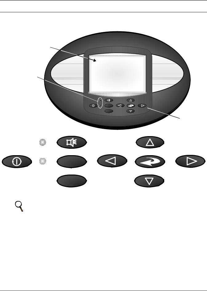
The small and the large display have a common key layout, as shown in Figure 2.
Figure 2 Liebert iCOM display components
Liquid Crystal Display
LED Status Indicators (top LED is red or  flashing red; bottom LED is green or amber)
Large Liebert iCOM Display shown - Keypad and LEDs are identical on all displays.
?
E S C
Keypad
|
Alarm Key |
|
Up Arrow Key |
|
|
? |
|
|
|
On/Off Key |
Help Key |
Left Arrow Key |
Enter Key |
Right Arrow Key |
|
ESC |
|
|
|
|
Escape Key |
|
Down Arrow Key |
|
NOTE
The Help key may be pressed at any time for a brief explanation of what is being viewed.
NOTICE
Risk of inadvertent system shutdown. Can cause loss of cooling and equipment damage.
Pressing the On/Off key on a Liebert iCOM large display while the system screen is shown permits shutting down all units on the network.
Large Liebert iCOM displays can view and control other units on the network when they are in the same group. When turning a unit Off or On with the large display, make sure that the unit to be shut down or started up is shown on the screen. If the system screen is shown and the On/Off key is pressed, the Liebert iCOM shows a notification that pressing the On/Off key again will turn Off all units on the network. See 7.5 - User-Display Setup Menu Screen to disable this function.
Liebert® iCOM® |
2 |
Liebert iCOM Display Components and Functions
Table 1 |
Keyboard icons and functions |
|
|
|
|
Icon |
Key Name |
Function |
|
On/Off Key |
Begins Shutdown or Startup. |
|
|
|
|
Alarm Key |
Silences/Resets an alarm. |
|
|
|
? |
Help Key |
Accesses integrated help menus. |
|
||
|
|
|
ESC |
ESCape Key |
Returns to the previous display view. |
|
|
|
|
Enter Key |
Confirms all selections and selects icons or text. |
|
|
|
|
Increase Key |
Moves upward in a menu or increases the value of a selected parameter. |
|
(Up Arrow) |
|
|
|
|
|
|
|
|
Decrease Key |
Moves downward in a menu or reduces the value of a selected parameter. |
|
(Down Arrow) |
|
|
|
|
|
|
|
|
Left and Right |
Navigates through text and sections of the display. |
|
Arrow Keys |
|
|
|
|
Blinking Red—Active, unacknowledged alarm exists
Upper LED
Solid Red—Active, acknowledged alarm exists
Amber—Power is available to the unit, unit is NOT operating
Lower LED
Green—Power is available to the unit, unit is operating
Lower LED |
Green and Amber LEDs will flash alternately when the unit is in Standby |
3 |
Liebert® iCOM® |
Liebert iCOM Display Components and Functions
2.1Control Interface—Large Display
The Liebert iCOM automatically opens to the Unit View Status Menu when the cooling unit is started. This view will display “Unit 1” in the upper right corner of the screen.
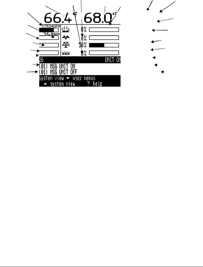
Figure 3 Unit view status menu
Setpoints |
|
|
|
|
(Return Temperature, Humidity |
|
|
Unit |
|
and Supply Temperature) |
|
|
||
|
|
|||
|
|
|
|
Identification |
|
|
|
|
|
|
|
|
||
|
|
|
|
|
Actual
Return
Temperature,
Humidity and
Supply
Temperature
Current Fan |
|
|
|
Next Scheduled |
|
||||
Speed |
|
|
|
Maintenance |
Percentage |
|
|
|
Date |
Current Cooling
Current  Status
Immediately
Preceding Status
Liebert iCOM
Navigation Guide
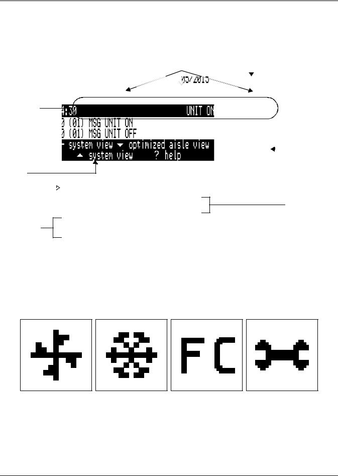
When no button on the Liebert iCOM control has been pressed for a short period, the display backlight turns Off. Pressing any key will reactivate the screen and display the status menu of the last cooling unit viewed.
The status menu will show the cooling unit’s operational mode, including information such as return air temperature and humidity readings, temperature and humidity setpoints and any active alarms.
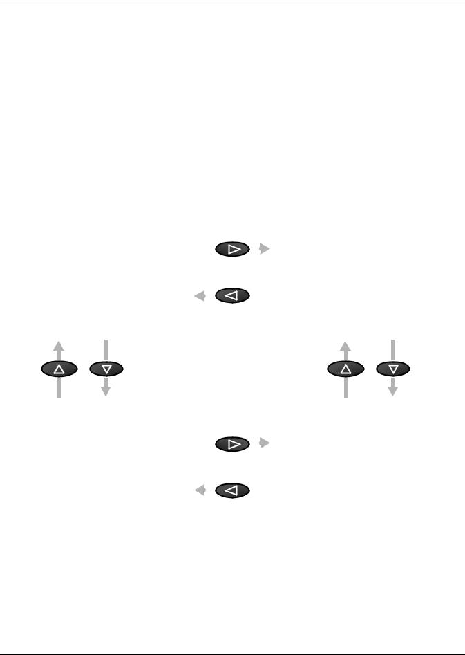
Symbols on the Liebert iCOM screens, shown in Figure 4, denote the operating modes.
Figure 4 Liebert iCOM default screen symbols
Fan |
Cooling |
Freecooling |
Maintenance |
|
|
|
|
|
|
|
|
|
|
|
|
|
|
|
|
|
|
|
|
|
|
|
|
|
|
|
|
|
|
|
|
|
|
|
|
|
|
|
|
|
|
|
|
|
|
|
|
|
|
|
|
|
|
|
|
|
|
|
|
|
|
|
|
|
|
|
|
|
|
|
|
|
|
|
|
|
|
|
|
|
|
|
|
|
|
|
|
|
|
|
|
|
|
|
|
|
|
|
|
|
|
|
|
|
|
|
|
|
|
|
|
|
|
|
|
|
|
|
|
|
|
|
|
|
|
|
|
|
|
|
|
|
|
|
|
|
|
|
|
|
|
|
|
|
|
|
|
|
|
|
|
|
|
|
|
|
|
|
|
|
|
|
|
|
|
|
|
|
|
|
|
|
|
|
|
|
|
|
|
|
|
|
|
|
|
|
|
|
|
|
|
|
|
|
|
|
|
|
|
|
|
|
|
|
|
|
|
|
|
|
|
|
|
|
|
|
|
|
|
|
|
|
|
|
|
|
|
|
|
|
|
|
|
|
|
|
|
|
|
|
|
|
|
|
|
|
|
|
|
|
|
|
|
|
|
|
|
|
|
|
|
|
|
|
|
|
|
|
|
|
|
|
|
|
|
|
|
|
|
|
|
|
|
|
|
|
|
|
|
|
|
|
|
|
|
|
|
|
|
|
|
|
|
|
|
|
|
|
|
|
|
|
|
|
|
|
|
|
|
|
|
|
|
|
|
|
|
|
|
|
|
|
|
|
|
|
|
|
|
|
|
|
|
|
|
|
|
|
|
|
|
|
|
|
|
|
|
|
|
|
|
|
|
|
|
|
|
|
|
|
|
|
|
|
|
|
|
|
|
|
|
|
|
|
|
|
|
|
|
|
|
|
|
|
|
|
|
|
|
|
|
|
|
|
|
|
|
|
|
|
|
|
|
|
|
|
|
|
|
|
|
|
|
|
|
|
|
|
|
|
|
|
|
|
|
|
|
|
|
|
|
|
|
|
|
|
|
|
|
|
|
|
|
|
|
|
|
|
|
|
|
|
|
|
|
|
|
|
|
|
|
|
|
|
|
|
|
|
|
|
|
|
|
|
|
|
|
|
|
|
|
|
|
|
|
|
|
|
|
|
|
|
|
|
|
|
|
|
|
|
|
|
|
|
|
|
|
|
|
|
|
|
|
|
|
|
|
|
|
|
|
|
|
|
|
|
|
|
|
|
|
|
|
|
|
|
|
|
|
|
|
|
|
|
|
|
|
|
|
|
|
|
|
|
|
|
|
|
|
|
|
|
|
|
|
|
|
|
|
|
|
Electric Heat |
|
|
|
|
|
|
|
|
|
|
|
|
|
|
|
|
|
|
|
|
|
|
|
|
|
|
|
|
|
|
|
|
|
|
|
||||||||||||
|
|
|
|
|
|
|
|
|
|
|
|
|
|
|
|
|
|
|
|
|
|
|
|
|
|
|
|
|
|
|
|
|
|
|
|
|
|
|
|
|
|
|
|
|
|
|
|
|
|
|
|
|
|
|
|
|
|||||||||||||
|
|
|
|
|
|
|
|
|
|
|
|
|
|
|
|
|
|
|
|
|
|
|
|
|
|
|
|
|
|
|
|
|
|
|
|
|
|
|
|
|
|
|
|
|
|
|
|
|
|
|
|
|
|
|
|
|
|||||||||||||
|
|
|
Hot Water |
|
|
|
Dehumidification |
|
|
Humidification |
|||||||||||||||||||||||||||||||||||||||||||||||||||||||||||
Liebert® iCOM® |
4 |
Liebert iCOM Display Components and Functions
A Liebert iCOM will show only icons for functions available on the unit it is connected to. For instance, a Liebert iCOM on a unit that does not perform humidification or dehumidification will not display icons for those functions.
Cooling systems may also disable functions temporarily for protective reasons. Icons for disabled functions will be displayed with a large X over them. The X will disappear when the function becomes available.
2.1.1Navigating to Various Views in the Liebert iCOM
Pressing any of the Liebert iCOM’s arrow keys in the Unit View Status Menu brings screens with different information.
The bottom of the screen serves as a navigation guide, illustrating what buttons do in various Liebert iCOM screens; see Figure 5).
Figure 5 Use arrow keys to navigate among screens
SYSTEM VIEW |
|
|
|
|
|
UNIT VIEW |
(No Teamwork) |
|
|
|
|
|
|
|
|
|
|
|
|
|
|
|
|
|
|
|
|
|
|
|
|
|
|
|
|
|
|
|
|
|
|
|
|
|
|
|
|
|
|
|
|
|
|
|
|
|
|
|
|
|
|
|
|
|
|
|
|
|
|
|
|
|
|
|
|
|
|
|
|
|
|
|
|
|
|
|
|
|
|
|
Use the Liebert iCOM arrow keys to move from one screen to another.
|
|
|
|
|
|
|
|
|
|
|
|
|
|
|
|
|
|
|
|
|
|
|
|
|
|
|
|
|
|
|
|
|
|
|
|
|
|
|
|
|
|
|
|
|
|
|
|
|
|
|
|
|
|
|
|
|
|
|
|
|
|
|
|
|
|
|
|
|
|
|
|
|
|
|
|
|
|
|
|
|
|
|
|
|
|
|
|
SYSTEM VIEW |
|
|
|
|
|
|
UNIT VIEW |
Rack View of Sensors |
|
|
|
|
|
|
Rack Sensor Temperatures |
5 |
Liebert® iCOM® |
|
|
|
|
|
|
|
|
|
|
|
Liebert iCOM Display Components and Functions |
|||||||||
|
|
|
|
|
|
|
|
|
|
|
|
|
|
|
|
|
|
|||
Figure 6 Unit status menu, large display, graphical comma view |
|
|
|
|
|
|
|
|
|
|||||||||||
|
|
|
Return Air |
Fluid |
Air Flow Return Air |
|
|
|
|
|
|
|
|
|
|
|||||
|
|
|
Flow |
|
Unit Name |
|
|
|||||||||||||
|
|
|
Temperature |
Rate |
Humidity |
|
|
System or |
||||||||||||
|
|
|
|
|
|
|
|
|
|
|
|
|||||||||
Return Air |
Setpoint |
|
Setpoint |
Return Air |
|
|
|
|
|
|
|
|
Unit # view |
|||||||
|
|
|
|
|
|
|
|
Humidity |
|
|
|
|
|
|
|
|
|
|||
Temperature |
|
|
|
|
|
|
|
|
|
|
|
|
|
|
|
|
Supply Air |
|||
|
|
|
|
|
|
|
|
|
|
|
|
|
|
|
|
|||||
|
|
|
|
|
|
|
|
|
|
|
|
|
|
|
|
|
|
|
||
Static Pressure |
|
|
|
|
|
|
|
|
|
|
|
|
|
|
|
|
Setpoint) |
|||
|
|
|
|
|
|
|
|
|
|
|
|
|
|
|
Supply Air |
|||||
|
|
|
|
|
|
|
|
|
|
|
|
|
|
|
|
|
|
|||
Evaporator |
|
|
|
|
|
|
|
|
|
|
|
|
|
|
|
Temperature |
||||
|
|
|
|
|
|
|
|
|
|
|
|
|
|
|
(optional) |
|||||
Fan Speed |
|
|
|
|
|
|
|
|
|
|
|
|
|
|
|
|||||
|
|
|
|
|
|
|
|
|
|
|
|
|
Percent Hot Water |
|||||||
Cooling Capacity |
|
|
|
|
|
|
|
|
|
|
|
|
|
|||||||
|
|
|
|
|
|
|
|
|
|
|
|
|
Heating |
|||||||
Percent Cooling |
|
|
|
|
|
|
|
|
|
|
|
|
|
|
|
Percent Electric |
||||
|
|
|
|
|
|
|
|
|
|
|
|
|
|
|
Heating |
|||||
Free-Cooling |
|
|
|
|
|
|
|
|
|
|
|
|
|
|
|
|
|
|||
|
|
|
|
|
|
|
|
|
|
|
|
|
|
Percent Dehumidifying |
||||||
Percentage |
|
|
|
|
|
|
|
|
|
|
|
|
||||||||
|
|
|
|
|
|
|
|
|
|
|
|
|||||||||
|
|
|
|
|
|
|
|
|
|
|
|
|
|
|
|
|
|
|||
Next Maintenance |
|
|
|
|
|
|
|
|
|
|
|
|
|
Percent Humidifying |
||||||
|
|
|
|
|
|
|
|
|
|
|
|
|
||||||||
Date and Time |
|
|
|
|
|
|
|
|
|
|
|
|
|
|
|
|
|
Unit Status |
||
|
|
|
|
|
|
|
|
|
|
|
|
|
|
|
|
|
||||
|
|
|
|
|
|
|
|
|
|
|
|
|
|
|
|
|
|
Most Recent Log |
||
|
|
|
|
|
|
|
|
|
|
|
|
|
|
|
|
|
|
|||
|
|
|
|
|
|
|
|
|
|
|
|
|
|
|
|
|
|
|||
|
|
|
|
|
|
|
|
|
|
|
|
|
|
|
|
|
|
Events (Date, |
||
|
|
|
|
|
|
|
|
|
|
|
|
|
|
|
|
|
|
|||
Liebert iCOM |
|
|
|
|
|
|
|
|
|
|
|
|
|
|
|
|
Time, Unit, |
|||
|
|
|
|
|
|
|
|
|
|
|
|
|
|
|
Description) |
|||||
Navigation |
|
|
|
|
|
|
|
|
|
|
|
|
|
|
|
|||||
|
|
|
|
|
|
|
|
|
|
|
|
|
|
|
|
|
|
|||
Guide |
|
|
|
|
|
|
|
|
|
|
|
|
|
|
|
|
|
|
||
|
|
|
|
|
|
|
|
|
|
|
|
|
|
|
|
|
|
|||
Figure 6 shows all icons and status bars for illustration only. Not all icons and status bars will be displayed on a particular unit. The Liebert iCOM will display icons and status only for functions available on the unit it is attached to. Some icons may, at times, be shown with an X over them, indicating that the function is temporarily disabled. The X will disappear when the component or function is re-enabled.
2.2System Screen
The System Screen with Rack View of Sensors will display the average, maximum and minimum of all connected sensors for the supply, return and remote sensors.
This screen may display the total airflow of the connected units within the group, static pressure control point and temperatures reported by the wireless sensor(s) when the applicable devices are installed.
Liebert® iCOM® |
6 |
Liebert iCOM Display Components and Functions
Figure 7 System screen with rack view of sensors
|
|
|
|
Fan Control |
Total System |
Teamwork Mode |
|||||
|
|
|
|
Sensor |
Airflow |
||||||
|
|
|
|
|
|
|
|
System |
|||
|
|
|
|
|
|
|
|
|
|
|
|
|
|
|
|
|
|
|
|
|
|
|
|
|
|
|
|
|
|
|
|
|
|
|
Percent Fan |
|
|
|
|
|
|
|
|
|
|
System Percen |
|
Fan Control |
|
|
|
|
|
Cooling |
|||||
|
|
|
|
|
|
|
|||||
Type (System, |
|
|
|
|
|
Calculated Next |
|||||
BMS or Local) |
|
|
|
|
|
Maintenance |
|||||
Cooling Control |
|
|
|
|
|
Wireless Sensor |
|||||
|
|
|
|
|
Non-Weighted |
||||||
Type (System or |
|
|
|
|
|
||||||
|
|
|
|
|
Value |
||||||
Local) |
|
|
|
|
|
||||||
|
|
|
|
|
Wireless |
||||||
|
|
|
|
|
|
|
|
|
|
||
|
|
|
|
|
|
|
|
|
|
Sensor |
|
|
|
|
|
|
|
|
|
|
|
Weighted Value |
|
Date and Time |
|
|
|
|
|
|
|
|
System |
||
|
|
|
|
|
|
|
|||||
|
|
|
|
|
|
||||||
|
|
|
|
|
|
|
|
|
|
|
Status |
|
|
|
|
|
|
|
|
|
|
|
|
Most Recent
System Events
(Date, Time, Unit,
Description) Navigation
Guide
System Screen will indicate if Teamwork is turned On and which teamwork mode is currently set within the control.
This system screen displays the unit operation by displaying the average of all active components from each unit within the system.
Figure 8 System screen
7 |
Liebert® iCOM® |

Liebert iCOM Display Components and Functions
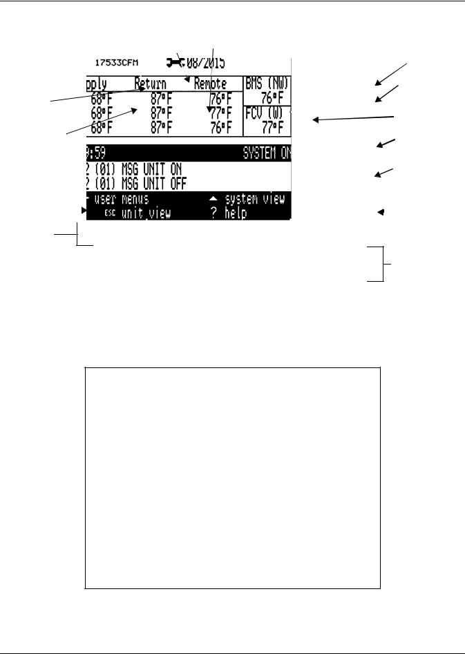
2.3Unit View with Rack Sensors
This screen is shown when rack sensors have been configured for control or reference. The temperatures at the top of the main unit screen are based on which sensors are used for controlling airflow, cooling capacity and humidification.
The data at the upper left of the screen can be either average or maximum rack temperature, depending on the selection in the Remote Sensors Mode. The data at the upper middle of the screen can be either dew point or relative humidity, depending on humidity control type.
Each unit can display individual remote rack sensor readings. The readings will be either an average or maximum reading between the two sensors connected at each 2T sensor module.
The bar graph’s upper limit is set at 77°F (25.0°C). The lower limit is set at 68°F (20°C), the rack inlet temperature range recommended by ASHRAE. When a rack temperature is at or above the upper limit, the bar graph will be all black. When a rack temperature is at or below the lower limit, the bar graph will be all white.
Figure 9 Unit view with rack sensor temperatures
Can be either dew point  or relative humidity
Can be either average
temperature
or maximum temperature
 Arrow will be shown when compensation is being performed
2.4Navigating Through the Liebert iCOM Menus
Liebert iCOM shows icons and text for monitoring and controlling your Liebert cooling units or network of cooling units. The number of icons and amount of text shown depends on the display size.
The Liebert iCOM has three main menus; User, Service and Advanced.
The User menu contains the most frequently used features, settings and status information. The Service menu contains settings and features used to set up unit communications and for unit maintenance. The Advanced menu contains settings used to set up the unit at the factory. Do not attempt to make any changes in the Advanced menu without consulting the factory first.
NOTE
Menu settings may be viewed without a password, but changing settings requires a password. The password for the User menu is 1490. The password for Service menu is 5010. For details on entering a password, see Entering a Password on page 12
Liebert® iCOM® |
8 |
Liebert iCOM Display Components and Functions
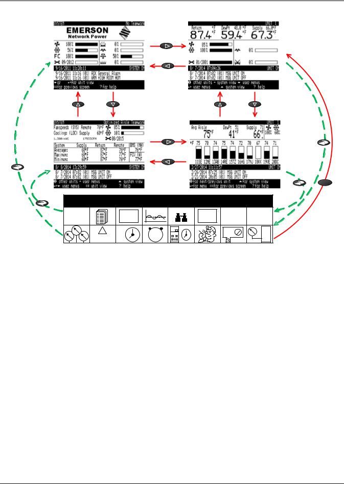
2.4.1Accessing Submenus on Large Displays
While the display is at unit status screen, press either the Enter or Down arrow key to display the User menu. To access the Service menu, press the Right arrow key. Pressing the Right arrow key again will display the Advanced menu.
Pressing the Enter key again will display the menu items. Use the arrow keys to navigate through the icons. When the desired icon highlighted, press the Enter key to enter that submenu. Once in a Submenu, a list of parameters will be displayed.
The Up and Down arrow keys may be used to scroll through the parameters page-by-page if the submenu has multiple pages. To scroll item-by-item, press the Enter key and then use the Up and Down arrow keys. Using the Right or Left arrow keys on large displays attached to a network will change the unit being viewed. Pressing the ESC key will go back a level. Figures 10 and 15 show the Liebert iCOM menus for a stand-alone large display and for a networked large display, respectively.
NOTE
Settings are readable without a password.t Changing settings requires a password.
Figure 10 Menu tree—Large display, stand-alone
Status Menu—System View
The unit name and U2U address will be displayed in the top right corner of the screen by default. The U2U address may be hidden, depending on settings
Status Menu in User Menu>Display Setup.
Unit 1 View
|
|
|
|
|
|
|
|
|
|
|
|
|
|
|
|
|
|
|
|
User Menu |
|
|
Service |
Menu |
|
Advanced Menu |
|||
Unit # |
|
|
Unit # |
|
Unit # |
||||
Password |
|
|
Password |
|
Password |
||||
Setpoints |
|
|
Setpoints |
|
Factory Settings |
||||
Spare Part List |
|
|
Unit Diary |
|
Expert Settings |
||||
Event Log |
|
Standby Settings/Lead-Lag |
|
Compressor Info |
|||||
Graphics |
|
Maintenance/Wellness Settings |
|
Expansion Device View |
|||||
View Network |
|
Diagnostics / Service Mode |
|
MBV Settings |
|||||
Set Alarms |
|
|
Set Alarms |
|
Change Passwords |
||||
Sensor Data |
|
|
iCOM-DO |
|
Runtime Monitoring |
||||
Active Alarms |
|
Sensor Calibration/Setup |
|
Control Override |
|||||
Display Setup |
|
|
Economizer |
|
Global Condenser Parameters |
||||
Total Run Hours |
|
System/Network Setup |
|
|
|
||||
Sleep Mode |
|
|
Options Setup |
|
|
|
|||
Service Contact Info |
|
Service Contact Info |
|
|
|
||||
Remote Sensors |
|
|
Remote Sensors |
|
|
|
|||
|
|
|
|
||||||
Condenser Timer |
|
Expansion Device Setup |
|
|
|
||||
|
|
|
|
|
|
|
|
|
|
9 |
Liebert® iCOM® |
Liebert iCOM Display Components and Functions
Figure 11 Navigation with a large display—single unit view
ESC
USER MENUS
°C / °F |
EVENT |
|
|
SET |
||
% RH |
|
|
||||
LOG |
|
|
|
ALARMS |
||
SET |
|
|
|
|||
|
|
|
|
|
||
! |
1 |
2 |
1234 |
12 |
MOD |
|
ACTIVE |
9 6 |
3 |
9 6 3 |
BUS |
||
h |
||||||
ALARMS |
SET |
|
|
|
E.D. |
|
Liebert® iCOM® |
10 |

Liebert iCOM Display Components and Functions
Figure 12 Navigation with a large display—Network view
ESC |
ESC |
USER MENUS
°C / °F |
EVENT |
|
|
|
SET |
|
% RH |
|
|
|
|||
|
LOG |
|
|
|
ALARMS |
|
SET |
|
|
|
|
||
|
|
|
|
|
|
|
! |
|
1 2 |
3 |
1234 |
9123 |
MOD |
ACTIVE |
|
9 |
BUS |
|||
SET |
6 |
|
h |
6 |
E.D. |
|
ALARMS |
|
|||||
|
|
|
|
|||
2.4.2Accessing Submenus on Small Displays
While the display is at the main menu (User, Service or Advanced), use the Up and Down arrow keys to scroll through the icons a page at a time. To scroll through the icons one-by-one, press the Enter key and use the Up and Down arrow keys. Select the desired icon, press the Enter key to view that submenu’s contents.
Press the Enter key and use the Up and Down arrow keys to navigate through the parameters one by one.
Pressing the ESC key will go back a level. Figure 13shows the Liebert iCOM menus for a small display.
Figure 13 Menu tree—Small display, stand-alone or networked
Status Menu
Unit 1 View
|
|
|
|
|
|
|
|
|
|
|
|
|
|
|
|
User Menu |
|
Service Menu |
|
Advanced Menu |
|||
Password |
|
Unit 1 |
|
Password |
|||
Setpoints |
|
Password |
|
Factory Settings |
|||
Event Log |
|
Setpoints |
|
|
|
||
|
|
|
|
||||
Graphics |
|
Standby Settings/Lead-Lag |
|
|
|
||
Set Alarms |
|
Maintenance/Wellness Settings |
|
|
|
||
Sensor Data |
|
Diagnostics / Service Mode |
|
|
|
||
Active Alarms |
|
Set Alarms |
|
|
|
||
Display Setup |
|
Sensor Calibration/Setup |
|
|
|
||
Total Run Hours |
|
Economizer |
|
|
|
||
Sleep Mode |
|
System/Network Setup |
|
|
|
||
Service Info |
|
Options Setup |
|
|
|
||
|
|
|
Service Contact Info |
|
|
|
|
|
|
|
|
|
|||
|
|
|
Remote Sensors |
|
|
|
|
|
|
|
|
|
|
|
|
11 |
Liebert® iCOM® |

Liebert iCOM Display Components and Functions
2.5Display Setup
The Liebert iCOM can be programmed to display information based on user preferences in the User Menu> Display Setup icon. Here the user can set things such as display Language, units of measure, set screen contrast and hide/show certain display readouts.
A display filtering feature located within the Display setup menu allows the user to display information of a single unit in the network on the large display. This allows each cooling unit to have a large display that acts as a local display.
A system On/Off enable feature allows the user to enable and disable the I/O button from the System view. This helps to protect against accidental system shut downs.
The user may also hide and show the U2U network number to the right of the unit name to allow for more flexible unit naming.
The Liebert iCOM supports multiple unit and system screen layouts. These screen layouts are configured on line U408 of the user menus, Display Setup icon.
U408 Screen selections include:
•Simple (factory default)
•Graphical
•Simple comma
•Graphical comma
The graphical settings allow the user to view a graphical representation of the iCOM operations.
The simple setting shows the operating status only of components currently operating. If a component is not in use, the Liebert iCOM automatically hides that component’s icon.
Both graphical comma and simple comma allow the user to see temperature and humidity reading to a tenth of a degree or percent.
2.5.1Entering a Password
The password must be entered before any value of the menu item parameter can be changed. There are three levels of password for preventing unauthorized changes.
1.User menu password allows the operator the ability to change the parameters in the User menu. The User menu password is 1490.
2.Service menu password enables the operator to changes parameters in both Service and User. The Service menu password is 5010.
3.Advanced menu password allows the changes to be made in all parameters.
NOTE
Entering the Service menu password permits access to both the User and Service menus.
To enter a password:
1.Navigate to the menu that contains the parameter to be changed.
2.Select Password in the submenu by pressing the Enter key.
3.Press the Enter key to move your cursor to the right side of the screen to select the question marks.
4.Use the arrow keys to enter the numeral for the password’s first digit (the Up arrow key moves from 1 to the next digit).
5.Use the Right arrow key to move to the next question mark and repeat Step 4 to enter all digits in the password.
6.After entering the password, press enter.
If the password is correct, the Actual Level shown to the right of Password will change from 0 to 1 or 2. The menu will remain locked if the password was incorrect.
NOTE
Returning to the Status menu will require re-entering a password to make changes.
Liebert® iCOM® |
12 |
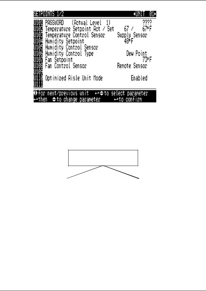
Liebert iCOM Display Components and Functions
Figure 14 Entering a password
2.5.2Viewing Multiple Units with a Networked Large Display
When you first wake up the control, press the Esc key to return to the System view Status menu. This view shows an average of all the units on the network and any alarms present. To view a specific unit on the network, press either the Enter key or Down arrow key. When you do this, you will see the word System in the top left of the screen change to a unit number. Use the Left and Right arrow keys to can toggle through the various units on the network. To go back to the System view, or back one level from any menu in the control, press the Esc key.
Figure 15 Menu tree—Large display, networked
The unit name and U2U address will be displayed in the top right corner of the screen by default. The U2U address may be hidden based settings in User Menu>Display Setup.
Status Menu—System View
(Networked Large Display Only)
Status Menu |
|
Status Menu |
||
Unit 1 View |
|
Unit 2, 3, 4 ... |
||
|
||||
|
|
|
|
|
|
|
|
|
|
|
|
|
|
|
|
|
|
User Menu |
|
Service |
Menu |
|
Advanced Menu |
||
Unit # |
|
Unit # |
|
Unit # |
|||
Password |
|
Password |
|
Password |
|||
Setpoints |
|
Setpoints |
|
Factory Settings |
|||
Spare Part List |
|
Unit Diary |
|
Expert Settings |
|||
Event Log |
|
Standby Settings/Lead-Lag |
|
Compressor Info |
|||
Graphics |
|
Maintenance/Wellness Settings |
|
MBV Settings |
|||
View Network |
|
Diagnostics / Service Mode |
|
Change Passwords |
|||
Set Alarms |
|
Set Alarms |
|
Runtime Monitoring |
|||
Sensor Data |
|
iCOM-DO |
|
Control Override |
|||
Active Alarms |
|
Sensor Calibration/Setup |
|
Global Condenser |
|||
Display Setup |
|
Economizer |
|
Condenser Control |
|||
Total Run Hours |
|
System/Network Setup |
|
|
|
||
|
|
|
|
||||
Sleep Mode |
|
Options Setup |
|
|
|
||
Service Contact Info |
|
Service Contact Info |
|
|
|
||
Remote Sensors |
|
Remote Sensors |
|
|
|
||
Condenser Timer |
|
|
|
|
|
|
|
|
|
|
|
|
|
||
|
|
|
|
|
|
|
|
13 |
Liebert® iCOM® |
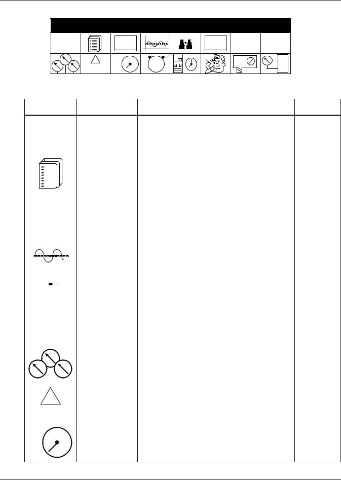
Liebert iCOM Display Components and Functions
Figure 16 User menu icons
USER MENUS
°C / °F |
EVENT |
|
|
SET |
||
% RH |
|
|
||||
|
LOG |
|
|
ALARMS |
||
SET |
|
|
|
|||
|
|
|
|
|
||
! |
|
9 1 2 3 |
1234 |
9123 |
MOD |
|
|
BUS |
|||||
ACTIVE |
SET |
6 |
h |
6 |
E.D. |
|
ALARMS |
||||||
|
|
|
||||
User Menu password: 1490
Table 2 |
User menu icons |
|
|
|
|
|
|
|
|
|
Available |
Icon |
Name |
Description |
On Display |
|
|
°C / °F |
|
|
|
||||||||||||
|
|
|
% RH |
Setpoints |
View and change temperature and humidity setpoints |
Small & Large |
|||||||||||
|
|
|
|
SET |
|
|
|
||||||||||
|
|
|
|
|
|
|
|
|
|
|
|
|
|
|
|
|
|
|
|
|
|
|
|
|
|
|
|
|
|
|
|
|
Spare Part List |
Displays the various part numbers of the |
Large |
|
|
|
|
|
|
|
|
|
|
|
|
|
|
|
|||
|
|
|
|
|
|
|
|
|
|
|
|
|
|
|
|||
|
|
|
|
|
|
|
|
|
|
|
|
|
|
|
components/parts in the cooling unit |
||
|
|
|
|
|
|
|
|
|
|
|
|
|
|
|
|
|
|
|
|
|
|
|
|
|
|
|
|
|
|
|
|
|
|
|
|
|
|
|
|
|
|
|
|
|
|
|
|
|
|
|
|
|
|
|
|
|
|
|
|
|
|
|
|
|
|
|
|
|
|
|
|
|
|
|
|
|
|
|
|
|
|
|
|
|
|
|
|
|
|
|
|
|
|
|
|
|
|
|
|
|
|
|
|
|
|
|
|
|
|
|
EVENT |
|
Event Log |
Contains last 400 events |
Small & Large |
||||||||||
|
|
|
|
LOG |
|
||||||||||||
|
|
|
|
|
|
|
|
||||||||||
|
|
|
|
|
|
|
|
|
|
|
|
|
|
|
|
|
|
|
|
|
|
|
|
|
|
|
|
|
|
|
|
|
|
|
|
|
|
|
|
|
|
|
|
|
|
|
|
|
|
|
Graphics |
Displays temperature and humidity graphs |
Small & Large |
|
|
|
|
|
|
|
|
|
|
|
|
|
|
|
|||
|
|
|
|
|
|
|
|
|
|
|
|
|
|
|
|
|
|
|
|
|
|
|
|
|
|
|
|
|
|
|
|
|
|
|
|
|
|
|
|
|
|
|
|
|
|
|
|
|
|
|
View Network |
Shows status of all connected units |
Large |
|
|
|
|
|
|
|
|
|
|
|
|
|
|
|
|||
|
|
|
|
|
|
|
|
|
|
|
|
|
|
|
|||
|
|
|
|
|
|
|
|
|
|
|
|
|
|
|
|
|
|
|
|
|
|
|
|
|
|
|
|
|
|
|
|
|
|
|
|
|
|
|
|
|
|
|
|
|
|
|
|
|
|
||||
|
|
|
|
SET |
|
Set Alarms |
Allows enable, disable and settings for alarms |
Small & Large |
|||||||||
|
|
ALARMS |
|
||||||||||||||
|
|
|
|
|
|
||||||||||||
|
|
|
|
|
|
|
|
|
|
|
|
|
|
|
|
|
|
|
|
|
|
|
|
|
|
|
|
|
|
|
|
|
|
|
|
|
|
|
|
|
|
|
|
|
|
|
|
|
|
|
Sensor Data |
Shows readings of standard and optional sensors |
Small & Large |
|
|
|
|
|
|
|
|
|
|
|
|
|
|
|
|||
|
|
|
|
|
|
|
|
|
|
|
|
|
|
|
|
|
|
|
|
|
|
|
|
|
|
|
|
|
|
|
|
|
|
|
|
|
|
|
|
|
|
! |
|
|
|
|
|
|
|
|
Active Alarms |
Allows the user to view all current active alarms |
Small & Large |
|
|
|
|
|
|
|
|
|
|
|
|
|
|
|
|||
|
|
|
ACTIVE |
|
|
|
|||||||||||
|
|
ALARMS |
|
|
|
||||||||||||
|
|
|
|
|
|
1 |
|
2 |
|
|
|
Change settings for display: language, time, simple or |
|
||||
|
|
|
|
|
|
|
|
|
|
|
|||||||
9 |
|
|
|
|
3 |
Display Setup |
Small & Large |
||||||||||
|
|
graphic view |
|||||||||||||||
SET |
6 |
|
|
|
|
|
|||||||||||
|
|
|
|
|
|
||||||||||||
Liebert® iCOM® |
14 |
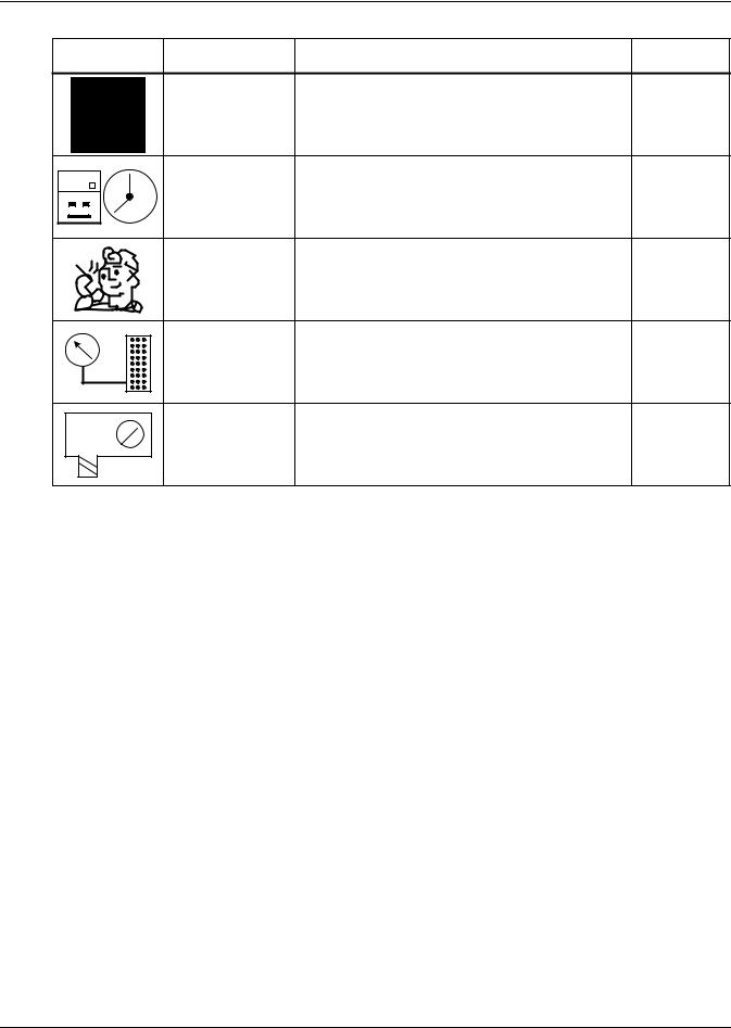
Liebert iCOM Display Components and Functions
Table 2 |
User menu icons (continued) |
|
||
|
|
|
|
Available |
Icon |
Name |
Description |
On Display |
|
1234h |
Total Run Hours |
Records the run time of all components and allows |
Small & Large |
|
setting of limits on run time |
||||
|
1 2 |
|
|
|
9 |
3 |
Sleep Mode |
Allows setback settings for non-peak operation |
Small & Large |
|
6 |
|
|
|
|
|
Service Contact Info |
Contains key contact information for local service, |
Small & Large |
|
|
|
including names and phone numbers |
|
|
|
Condenser Timer |
Displays the timer settings for the Liebert MC™ |
Large |
|
|
(microchannel condenser) |
||
|
|
|
|
|
MOD |
|
|
|
|
BUS |
|
Expansion Device |
Displays readings of Modbus devices |
Large |
E.D.
15 |
Liebert® iCOM® |
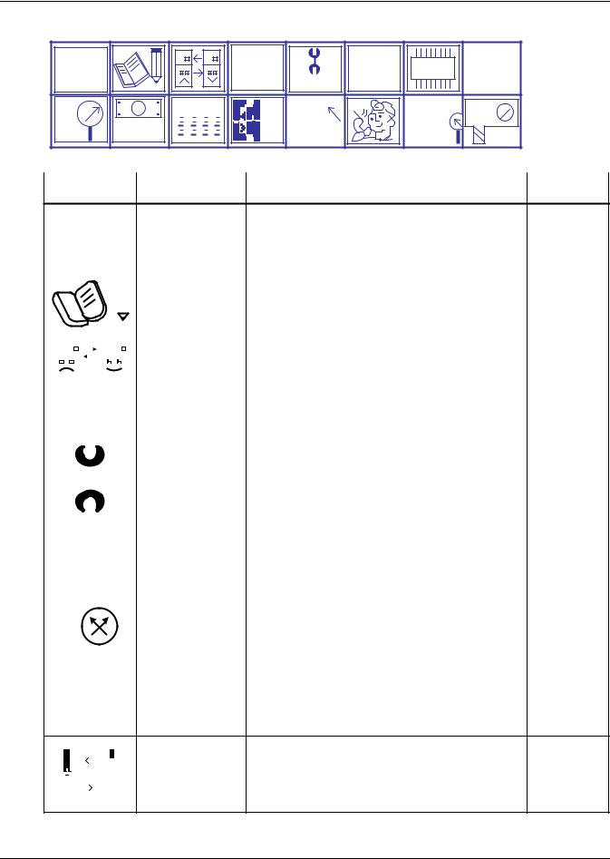
Liebert iCOM Display Components and Functions
Figure 17 Service menu icons
°C / °F |
|
+ |
|
SET |
DO |
|
% RH |
|
|
|
|||
|
WELLNESS |
SERVICE |
ALARMS |
|
||
SET |
|
|
|
|
||
|
NETWORK |
SET |
|
|
|
MOD |
+/- |
ECON |
UP |
|
|
REM |
BUS |
|
|
|
E.D. |
|||
|
|
|
SENSORS |
Service Menu password: 5010
Table 3 |
Service menu icons |
|
|
|
|
|
|
|
|
|
Available On |
Icon |
Name |
Description |
Display |
|
|
|
|
|
|
°C / °F |
|
|
|
||||||||
|
|
|
|
|
|
|
% RH |
Setpoints |
To view and change temperature and humidity setpoints |
Small & large |
|||||||
|
|
|
|
|
|
|
|
|
SET |
|
|
|
|||||
|
|
|
|
|
|
|
|
|
|
|
|
|
|
|
|
|
|
|
|
|
|
|
|
|
|
|
|
|
|
|
|
|
Unit Diary |
Shows all entered program changes and maintenance |
Large |
|
|
|
|
|
|
|
|
|
|
|
|
|
|
|
|||
|
|
|
|
|
|
|
|
|
|
|
|
|
|
|
performed on the unit |
||
|
|
|
|
|
|
|
|
|
|
|
|
|
|
|
|||
|
|
|
|
|
|
|
|
|
|
|
|
|
|
|
|
|
|
|
|
|
|
|
|
|
|
|
|
|
|
|
|
|
|
|
|
|
|
|
|
|
|
|
|
|
|
|
|
|
|
|
Standby Settings/ |
Allows lead/lag setup when multiple units are connected |
Small & large |
|
|
|
|
|
|
|
|
|
|
|
|
|
|
|
|||
|
|
|
|
|
|
|
|
|
|
|
|
|
|
|
|||
|
|
|
|
|
|
|
|
|
|
|
|
|
|
|
|||
|
|
|
|
|
|
|
|
|
|
|
|
|
|
|
|||
|
|
|
|
|
|
|
|
|
|
|
|
|
|
|
Lead-Lag |
||
|
|
|
|
|
|
|
|
|
|
|
|
|
|
|
|||
|
|
|
|
|
|
|
|
|
|
|
|
|
|
|
|
|
|
|
|
|
|
|
|
|
|
|
|
|
|
|
|
|
|
|
|
|
|
|
|
|
|
|
|
|
|
|
|
|
|
|
|
|
|
|
|
|
|
|
|
|
|
|
|
|
|
|
|
|
Maintenance/ |
Allows setting maintenance interval reminder, |
|
|
|
|
|
|
|
|
|
|
|
|
|
|
|
|
|
||
|
|
|
|
|
|
|
|
|
|
|
|
|
|
|
|
||
|
|
|
|
|
|
|
|
|
|
|
|
|
|
|
|
||
|
|
|
|
|
|
|
|
|
|
|
|
|
|
|
maintenance message, number of unit starts and stops, |
Small & large |
|
|
|
|
|
|
|
|
|
|
|
|
|
|
|
|
Wellness Settings |
||
|
|
|
WELLNESS |
and time since last maintenance |
|
||||||||||||
|
|
|
|
|
|||||||||||||
|
|
|
|
|
|
||||||||||||
|
|
|
|
|
|
|
|
|
|
|
|
|
|
|
|
|
|
|
|
|
|
|
|
|
|
|
|
|
|
|
|
|
Diagnostics/ |
Allows troubleshooting, manual mode, read analog and |
Small & large |
|
|
|
|
|
|
|
|
|
|
|
|
|
|
|
|||
|
|
|
|
|
|
|
|
|
|
|
|
|
|
|
Service Mode |
digital inputs |
|
|
|
|
|
|
|
SERVICE |
|
||||||||||
|
|
|
|
|
|
|
|
|
|||||||||
|
|
|
|
|
|
|
|
|
|
|
|
|
|
|
|
|
|
|
|
|
|
|
|
|
|
|
SET |
Set Alarms |
Allows enable, disable and settings for alarms |
Small & large |
|||||
|
|
|
|
|
|
ALARMS |
|||||||||||
|
|
|
|
|
|
|
|
|
|||||||||
|
|
|
|
|
|
|
|
|
|
|
|
|
|
|
|
|
|
|
|
|
|
|
|
|
|
|
|
|
|
|
|
|
|
|
|
+ / - |
|
|
|
|
|
Sensor |
Allows calibration of sensors |
Small & large |
|||||||||
|
|
|
|
|
Calibration/Setup |
||||||||||||
|
|
|
|
|
|||||||||||||
|
|
|
|
|
|
|
|
|
|
|
|
|
|
|
|
|
|
|
|
|
|
|
|
|
|
|
|
|
|
|
|
|
|
|
|
NETWORK |
System/Network |
|
|
||||||||||||||
|
|
|
|
|
|
|
|
|
|
|
|
|
|
|
Allows setup and U2U communication for multiple units |
Small & large |
|
|
|
|
|
|
|
|
|
|
|
|
|
|
|
|
|||
|
|
|
|
|
|
|
|
|
|
|
|
|
|
|
Setup |
||
|
|
|
|
|
|
|
|
|
|
|
|
|
|
|
|||
|
|
|
|
|
|
|
|
|
|
|
|
|
|
|
|
|
|
|
|
|
|
|
|
|
|
|
|
|
|
|
|
|
|
|
|
|
|
|
|
|
|
|
|
|
|
|
|
|
|
|
|
|
|
|
|
|
|
|
|
|
|
Options Setup |
Allows setup of component operation |
Small & large |
|
|
|
|
|
|
|
|
|||
|
|
|
|
|
|
|
|
|||
|
|
|
|
|
|
|
|
|||
|
|
|
|
|
|
|
|
|||
|
|
|
|
|
|
|
|
|||
|
|
|||||||||
|
|
|
|
|
|
|
|
|
|
|
|
|
|
|
|
|
|
|
|
|
|
|
|
|
|
|
|
|
|
|
|
|
Liebert® iCOM® |
16 |
|
|
Liebert iCOM Display Components and Functions |
|
Table 3 |
Service menu icons (continued) |
|
|
|
|
|
Available On |
Icon |
Name |
Description |
Display |
|
Service Contact |
Contains key contact information for local service, |
Small & large |
|
Info |
including names and phone numbers |
|
|
|
||
DO |
Liebert iCOM-DO™ |
Change settings for Liebert iCOM Discrete Output card |
Large |
|
|||
|
REM |
|
|
Remote Sensors |
Change settings for Remote Sensors |
Large |
|
|
|
||||||
|
SENSORS |
|
|
|
|
|
|
|
|
|
|
|
|
|
|
|
|
|
|
|
|
|
|
|
|
|
|
|
|
|
|
|
|
MOD |
|
|
|
|
|
|
|
BUS |
|
Expansion Device |
Displays readings of Modbus devices |
Large |
|
E.D.
17 |
Liebert® iCOM® |

Operation
3.0OPERATION
The Liebert iCOM display provides viewing, trending and configuration capability for Liebert cooling units. All unit settings and parameters can be viewed and adjusted through three menus: User, Service and Advanced. All active alarms are displayed on the LCD and annunciated.
The control is shipped from the factory with default selections for all necessary settings. Adjustments can be made if the defaults do not meet your requirements.
References to menu items in this manual are followed by the main menu and the submenu where they can be found.
For example:
•Temperature Setpoint (User Menu, Setpoints) - The Temperature Setpoint parameter is located in the User menu under the Setpoints submenu.
•High Return Humidity (Service Menu, Set Alarms) - The High Return Humidity alarm is located in the Service menu under the Set Alarms submenu.
3.1Single Unit Functions
3.1.1Unit/Fan Control Start - Stop
The unit may be switched On and Off by pressing the On/Off button, through a remote device or by internal safety device(s). In all cases, the fan output is first activated when the unit is switched On and will remain On as long as the unit is running. Each time a unit is turned On or Off, the unit status is updated to reflect the current operating mode and an event is added to the Event Log. Unit statuses displayed include:
•ALARM OFF—The unit has an alarm that has forced the unit to turn Off.
•MANUAL—Unit is being controlled by a service technician using the Service Diagnostics Manual Mode.
•LOCAL OFF—When a unit is turned Off from the Unit Status Screen or small display, LOCAL OFF is shown for unit status.
•DISPLAY OFF—When a unit is turned Off from the System Screen of a large display, Display OFF is shown for unit status.
•ALARM STANDBY—The unit has been rotated into standby because an active alarm on the unit is present.
•STANDBY—The unit is in standby based on the Lead / Lag settings in the Service Menu.
•TIMER OFF—The unit has been set to Sleep and is waiting for the next start interval. See User / Sleep Mode Menu.
•UNIT ON—The unit is operating normally without alarm or warning.
•WARNING ON—The unit has an active warning but is still operating. See User / Active alarms for details.
•ALARM ON—The unit has an active alarm but is still operating. See User / Active alarms for details.
•TIMER—The unit is configured on a timer to only operate at certain times. See User / Sleep Mode Menu.
•REMOTE OFF—Remote shutdown terminals will turn Off the connected unit and the front display shows REMOTE OFF as the status. This command is invoked when a normally closed set of dry contacts opens. The remote On/Off and display On/Off switches are in series. A cooling unit will start only if both switches are On. If one of these switches is Off, the unit will stop. See Figure 18 for more information.
•MONITORNG OFF—In this case, an override to the monitoring is possible: Pressing the On-Off button of the display will change the state to Unit Off; pressing again may start the unit in Unit On. If the unit does not turn On, check the remote monitoring device or call 800-543-2778 for assistance.
•BACK-DRAFT—The unit is in a non-operational mode, but is operating the EC fan as a back-draft damper.
Liebert® iCOM® |
18 |
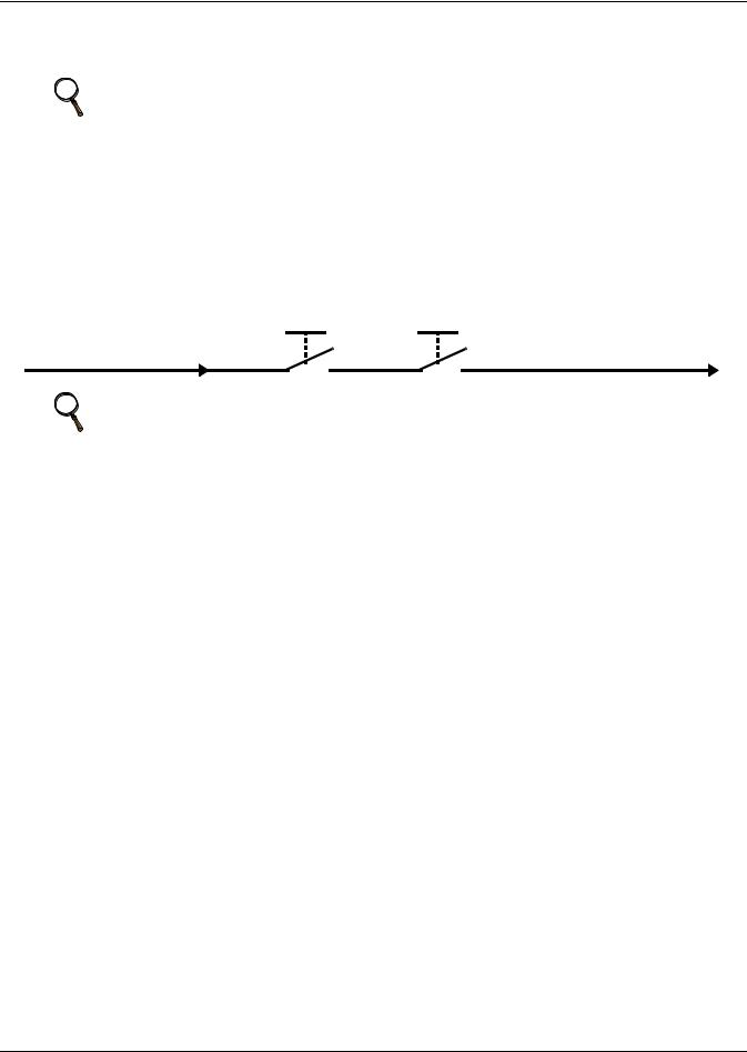
Operation
Pressing the On/Off key on a small display will affect only the cooling unit it is mounted on, regardless of whether the cooling unit is a stand-alone unit or part of a network. The small Liebert iCOM display does not have access to the Unit-to-Unit network.
NOTE
Pressing the On/Off key on a large display of a stand-alone cooling unit will control
only that unit.
The effect of pressing the On/Off key on a large display connected to a network depends on the view: System or Unit.
•In System view, pressing the On/Off key shows a warning asking for confirmation to shut down the entire system.
•In Unit view, pressing the On/Off key affects only the unit being viewed, without a confirmation request.
Each time a unit is powered On or Off, an event is added to the Event Log in the User menu.
Figure 18 Start-stop priority switches
Remote On / Off Display On / Off
NOTE
If Remote On/Off is not used, a jumper is inserted to bypass the switch.
Autorestart
When input power returns after a power failure, the unit will return to its previous operating status: On if it was On before the power failure, Off if it was Off.
When power returns, the autorestart time—time-selectable: Single Unit Auto Restart (Service Menu, Options Setup)—will determine how quickly the unit restarts.
Loss of Power Alarm
A Loss of Power Alarm is activated when power is restored after an interruption. If acknowledged, the alarm resets automatically after 30 minutes. This alarm can be set to different event types (Message, Alarm or Warning) and can be disabled under menu item Loss of Power (Service Menu, Set Alarms).
Fan Alarm / Fan Protection Settings
The fan operation is protected by two digital devices: motor protection (optional on VFD centrifugal and standard centrifugal drives) and a differential pressure switch. The motor protection monitors for main fan overload (Main Fan Overload alarm) or EC fan fault and the differential pressure switch detects a loss of airflow. If either protection device is activated after an adjustable time delay, an audible alarm occurs, an alarm relay activates and an event is recorded in the event log (Main Fan Overload or EC fan fault and Loss of Airflow in Service Menu > Set Alarms).
The fan delay at the unit start is always five seconds shorter than the control delay (to avoid shortcycling components when the fan is not working).
When a main fan overload occurs, the main fan, cooling, heating, humidification and dehumidification are disabled to prevent equipment damage; the unit status will show “Alarm Off.” The unit will automatically resume operation once the overload condition has cleared.
When an EC fan fault occurs, the unit will continue to operate normally unless a loss of airflow alarm occurs.
When a loss of airflow occurs, the fan(s) will continue to operate to keep the unit on line until the problem is corrected. Cooling, heating, dehumidification and humidification are disabled.
19 |
Liebert® iCOM® |
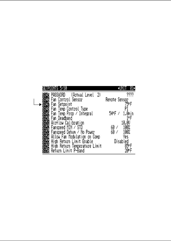
Operation
Variable Speed Fans—EC or Variable Frequency Drives
The Liebert iCOM control can adjust airflow manually through a BMS or dynamically using locally installed temperature sensors. Parameters related to VSD fan speed setting can be found in the Service Menu > Setpoints submenu on page 5 of 8. This menu allows the cooling unit's fan motor speed to be configured and adjusted for a variety of applications by selecting which sensor controls the fan speed.
Four fan control modes are available: Manual, Supply, Return and Remote. All units ship from the factory with the temperature control and fan speed control sensor set to the Return Air Sensor.
•Manual Control: When set to Manual, the speed of the fan motor can be wrote using a hard wired analog input or remotely through an optional Liebert IntelliSlot® card. Hard wired analog
input signal types include 4-20mA, 0-10 VDC or 0-5VDC. See 6.0 - External Communication— Building Management Systems, Liebert SiteScan® for more information regarding Liebert iCOM intellislot monitoring options.
Before the building management system can control the fan speed, two parameters in the control must be set. S146 “Fan Control Sensor” must read Manual and line S164 “Allow BMS to change Fanspeed” must be changed to YES at the Liebert iCOM. Both parameters are found in Service Menus > Service Setpoints.
Figure 19 Setting manual fan control and changing the setpoint
These commands 
 permit setting manual
fan control and changing the setpoint.
 Options for this are Return, Remote, Supply and Manual.
Fan speed may be written through the building management system to line S152. The user can change this locally. However, if the speed is set by the BMS, it will override the local setting.
•Supply, Return and Remote Control: These selections allow fan modulation using an equipped return, supply or remote sensor; see Table 4 for applicable control sensor combinations. If the fan control and the temperature control sensor have the same sensor selected, the control is considered coupled. If different sensors are selected, the control is considered decoupled. When operating the fan in coupled mode, the fan speed follows the call for cooling to reach the temperature setpoint. When the fans are operating in decoupled mode, the fans are ramped following the fan control band to achieve the fan setpoint.
Table 4 Controlling sensor settings
|
|
S103 Temperature Control Sensor |
|||
|
|
|
|
|
|
|
|
Supply |
Remote Sensor |
Return |
|
|
|
|
|
|
|
|
Supply |
Factory Default |
N/A |
N/A |
|
|
(Coupled) |
||||
S125 Fan |
|
|
|
||
|
Recommended |
|
|
||
Control Sensor |
Remote Sensor |
(Coupled) |
N/A |
||
(Decoupled) |
|||||
|
|
|
|
||
|
|
|
|
|
|
|
Return |
(Decoupled) |
(Decoupled) |
(Coupled) |
|
|
|
|
|
|
|
Liebert® iCOM® |
20 |
Loading...