


 Loading...
Español English
EMERSON AND THE G-CLEF LOGO ARE REGISTERED TRADEMARKS
OF EMERSON RADIO CORP., PARSIPPANY, NEW JERSEY, U.S.A.
32” LCD TV
LC320EM2F
EN Owner's Manual |
Need help? |
Please call toll free or visit our web site below |
|
FR |
Manuel du Propriétaire Besoin d’aide? |
Appelez notre numéro gratuit ou visitez notre site web à l’adresse |
|
ES |
Manual del Propietario |
¿Necesita ayuda? |
Llame por favor sin costo ó visite nuestro sitio web en |
1-866-309-8819
www.emersonaudiovideo.com
MODEL NUMBER |
SERIAL NUMBER |
© 2011 Funai Electric Co., Ltd. |
2
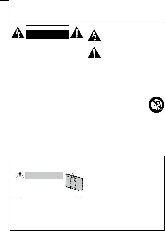
WARNING: TO REDUCE THE RISK OF FIRE OR ELECTRIC SHOCK, DO NOT EXPOSE THIS APPARATUS TO RAIN OR MOISTURE.
APPARATUS SHALL NOT BE EXPOSED TO DRIPPING OR SPLASHING AND NO OBJECTS FILLED WITH LIQUIDS, SUCH AS VASES, SHALL BE PLACED ON THE APPARATUS.
CAUTION |
|
|
an equilateral triangle, is intended to alert the |
|
|
|
The lightning flash with arrowhead symbol, within |
RISK OF ELECTRIC SHOCK |
|
|
user to the presence of uninsulated “dangerous |
DO NOT OPEN |
|
|
voltage” within the apparatus’s enclosure that may |
CAUTION: |
|
|
be of sufficient magnitude to constitute a risk of |
|
|
||
|
|
electric shock to persons. |
|
TO REDUCE THE RISK OF ELECTRIC SHOCK, DO |
|
|
The exclamation point within an equilateral triangle is |
NOT REMOVE COVER (OR BACK). NO USER |
|
|
intended to alert the user to the presence of important |
SERVICEABLE PARTS INSIDE. REFER SERVICING TO |
|
|
operating and maintenance (servicing) instructions in |
QUALIFIED SERVICE PERSONNEL. |
|
|
the literature accompanying the apparatus. |
The caution marking is located on the rear or bottom of the cabinet. |
|
||
Important Safety Instructions
1. Read these instructions.
2. Keep these instructions. 3. Heed all warnings.
4. Follow all instructions.
5. Do not use this apparatus near water. 6. Clean only with dry cloth.
7. Do not block any ventilation openings. Install in accordance with the manufacturer’s instructions.
8.Do not install near any heat sources such as radiators, heat registers, stoves, or other apparatus (including amplifiers) that produce heat.
9.Do not defeat the safety purpose of the polarized or grounding-type plug. A polarized plug has two blades with one wider than the other. A grounding type plug has two blades and a third grounding prong.The wide blade or the third prong are provided for your safety. If the provided plug does not fit into your outlet, consult an electrician for replacement of the obsolete outlet.
Wall Mount Bracket Kit
Recommended Wall Mount Bracket Kit:
Brand: Sanus Vuepoint |
Model #: F55 |
|
|
|
|
Do NOT use screws packed
withWall Mount Bracket Kit.
Recommended Screw dimension when purchased:
M4 x 0.787” (20mm) + Washer 0.078”(T2mm)
The recommended Wall Mount Bracket Kit (sold separately) allows the mounting of theTV on the wall.
For detailed information on installing the wall mount, refer to the Wall Mount Instruction Book.
Funai is not responsible for any damage to the product or injury to yourself or others if you elect to install theTVWall Mount Bracket or mount theTV onto the Bracket on your own.
The Wall Mount Bracket must be installed by experts.
10.Protect the power cord from being walked on or pinched particularly at plugs, convenience receptacles, and the point where they exit from the apparatus.
11.Only use attachments / accessories specified by the manufacturer.
12. Use only with the cart, stand,  tripod, bracket, or table specified
 by the manufacturer, or sold with


 the apparatus.When a cart is used,
  use caution when moving the cart / apparatus combination to avoid injury from tip-over.
13.Unplug this apparatus during lightning storms or when unused for long periods of time.
14.Refer all servicing to qualified service personnel. Servicing is required when the apparatus has been damaged in any way, such as power-supply cord or plug is damaged, liquid has been spilled or objects have fallen into the apparatus, the apparatus has been exposed to rain or moisture, does not operate normally, or has been dropped.
Funai not liable for these types of accidents or injury noted below.
Install the Wall Mount Bracket on a sturdy vertical wall. If installed onto a ceiling or slanted wall, theTV and Wall
Mount Bracket may fall which could result in a severe injury. Do not use screws that are longer or shorter than their specified length. If screws too long are used this may cause mechanical or electrical damage inside theTV set. If screws too short are used this may cause theTV set to fall.
Do not fasten the screws by excessive force; this may damage the product or cause the product to fall, leading to an injury. For safety reasons use 2 people to mount theTV onto a Wall Mounting Bracket.
Do not mount theTV onto the Wall Mounting Bracket while yourTV is plugged in or turned on. It may result in an electrical shock injury.
When installing the unit on the wall, allow this much space.
Top: |
11.8 inches (30cm) |
|
Left and right side: |
5.9 inches |
(15cm) |
Bottom: |
3.9 inches |
(10cm) |
English 3
FCC WARNING
This apparatus may generate or use radio frequency energy. Changes or modifications to this apparatus may cause harmful interference unless the modifications are expressly approved in the manual. The user could lose the authority to operate this apparatus if an unauthorized change or modification is made.
RADIO-TV INTERFERENCE
This apparatus has been tested and found to comply with the limits for a Class B digital device, pursuant to Part 15 of the FCC Rules. These limits are designed to provide reasonable protection against harmful interference in a residential installation. This apparatus generates, uses, and can radiate radio frequency energy and, if not installed and used in accordance with the instructions, may cause harmful interference to radio communications. However, there is no guarantee that interference will not occur in a particular installation. If this apparatus does cause harmful interference to radio or television reception, which can be determined by turning the apparatus off and on, the user is encouraged to try to correct the interference by one or more of the following measures:
1) Reorient or relocate the receiving antenna.
2)Increase the separation between the apparatus and receiver.
3)Connect the apparatus into an outlet on a circuit different from that to which the receiver is connected.
4)Consult the dealer or an experienced radio/TV technician for help.
DECLARATION OF CONFORMITY |
|
Trade Name: Emerson |
Responsible Party: FUNAI CORPORATION, Inc. |
Model: LC320EM2F |
Address: 19900 Van Ness Avenue, Torrance, CA 90501 U.S.A. |
|
Telephone Number: 1-866-309-8819 |
This Class B digital apparatus complies with Canadian ICES-003. StandardTelevision Receiving Apparatus, Canada BETS-7/NTMR-7
CAUTION: Danger of explosion if battery is incorrectly replaced. Replace only with the same or equivalent type. WARNING: Batteries (battery pack or battery installed) shall not be exposed to excessive heat such as sunshine, fire or the like.
Disconnect the mains plug to shut off when find trouble or not in use.The mains plug shall remain readily operable.
This apparatus should not be placed in a built-in installation such as a bookcase or rack unless proper ventilation is provided. Make sure to leave a space of 4 inches (10cm) or more around this apparatus.
WARNING: To prevent injury, this apparatus must be securely attached to the wall in accordance with the instructions.
Do not place the unit on the furniture that is capable of being tilted by a child and an adult leaning, pulling, standing or climbing on it. A falling unit can cause serious injury or even death.

 LAMP IN LCD CONTAINS MERCURY, DISPOSEACCORDINGTO LOCAL, STATE OR FEDERAL LAW.
The American Academy of Pediatrics discourages television viewing for children younger than two years of age.
NOTE ABOUT RECYCLING
This unit’s packaging materials are recyclable and can be reused. Please dispose of any materials in accordance with your local recycling regulations.
Batteries should never be thrown away or incinerated but disposed of in accordance with your local regulations concerning chemical wastes.
For product recycling information, please visit - www.emersonaudiovideo.com
WHEN CARRYINGTHIS UNIT
At least 2 people are required when carrying this unit.
Make sure to hold the upper and bottom frames of the unit firmly as illustrated.
TO AVOID THE HAZARDS OF ELECTRICAL SHOCK AND FIRE
Do not handle the AC power cord with wet hands.
Do not pull on the AC power cord when disconnecting it from an AC outlet. Grasp it by the plug.
Do not put your fingers or objects into the unit.
LOCATION AND HANDLING
Do not install the unit in direct sunlight or in a place subject to dust or strong vibration.
Avoid a place with drastic temperature changes.
Install the unit in a horizontal and stable position. Do not place anything directly on top or bottom of the unit. Depending on your external devices, noise or disturbance of the picture and/or sound may be generated if the unit is placed too close to them. In this case, please ensure enough space between the external devices and the unit. Depending on the environment, the temperature of this unit may ncrease slightly.This is not a malfunction.
Be sure to unplug the AC power cord from the AC outlet before moving or carrying the unit.
Trademark Information
HDMI, the HDMI Logo, and High-Definition Multimedia Interface are trademarks or registered trademarks of HDMI Licensing LLC in the United States and other countries.
Manufactured under license from Dolby Laboratories. Dolby and the double-D symbol are trademarks of Dolby Laboratories.
ENERGY STAR® is a joint program of the U.S. Environmental Protection Agency and the U.S. Department of Energy helping us all save money and protect the environment through energy efficient products and practices.
Consumer Notice:
This TV has been set to maximize energy efficiency while delivering the best possible picture using the factory installed home mode settings.
Changing or enabling other features in this TV (e.g. brightened backlighting) will possibly increase energy consumption beyond the original ENERGY STAR® qualified limits.

4
Child Safety
INTRODUCTION
Contents
Important Safety Instructions |
2 |
Trademark Information |
3 |
Child Safety |
4 |
INTRODUCTION
Features |
5 |
Supplied Accessories |
6 |
Symbols Used in this Manual |
6 |
Attaching the Base |
6 |
Mounting the Unit on Your Furniture |
6 |
Remote Control Function |
7 |
Installing the Batteries |
7 |
Control Panel |
8 |
Terminals |
9 |
PREPARATION
Antenna Connection |
10 |
Connection to Cable Receiver or Satellite Box |
10 |
Plug In the AC Power Cord |
10 |
Initial Setup |
11 |
WATCHING TV
Switching Each Input Mode |
12 |
Sleep Timer |
12 |
Sound Functions |
12 |
Freeze Mode |
13 |
TV Screen Display Mode |
13 |
Channel Selection |
13 |
TV Screen Information |
14 |
ECO |
14 |
USING FUNCTIONS
Picture |
16 |
Sound |
16 |
Setup |
17 |
Features |
18 |
Language |
23 |
USB |
24 |
CONNECTING DEVICES
External Device Connection |
25 |
USEFUL TIPS
FAQ |
28 |
Troubleshooting Guide |
28 |
INFORMATION
Glossary |
30 |
Maintenance |
30 |
General Specifications |
31 |
Electrical Specification |
31 |
Other Specifications |
31 |
Limited Warranty |
33 |
English
Features
•DTV /TV / CATV
You can use your remote control to select channels which are broadcast in digital format and conventional analog format. Also, cable subscribers can access their cable TV channels.
•Information Display (ATSC only)
You can display the title, contents and other information of the current DTV program on the TV screen.
•Autoprogram
This unit automatically scans and memorizes channels available in your area, eliminating difficult setup procedures.
•Child Lock
This feature allows you to block children’s access to inappropriate programs.
•Closed Caption Decoder
Built-in closed caption decoder displays text for closed caption supported programs.
•MTS / SAP Tuner
Audio can be selected from the remote control.
•Auto Standby
If there is no input signal and no operation for 15 minutes, the unit will go into standby mode automatically.
•Sleep Timer
You can set the unit to go into standby mode after a specific amount of time.
•Choices for On-screen Language
Select your on-screen language: English, Spanish or French.
•Stereo Sound Function
•PLL Frequency Synthesized Tuning
Provides free and easy channel selection and lets you tune directly to any channel using the number and decimal point “•” buttons on the remote control.
•Various Adjustment for Picture and Sound
Customizes image quality suitable for your room and sets your sound preference.
•fun-Link via HDMI Link
(HDMI Cable not Included)
fun-Link allows your other HDMI link devices to be controlled by the HDMI cable connected to your TV.
•HDMI Input
•HDMI-DVI Input
If your video device has DVI output jack, use an HDMI-DVI conversion cable to connect the unit.
•Component Video Input
•PC Input
•AV Input
•USB Terminal
The picture (JPEG) and video (Motion JPEG) files stored on a USB storage device can be played back on this unit.
• Digital Audio Output
5
INFORMATION TIPSUSEFUL DEVICES CONNECTING FUNCTIONS USING TV WATCHING PREPARATION INTRODUCTION
© 2011 Funai Electric Co., Ltd.
All rights reserved. No part of this manual may be reproduced, copied, transmitted, disseminated, transcribed, downloaded or stored in any storage medium, in any form or for any purpose without the express prior written consent of Funai. Furthermore, any unauthorized commercial distribution of this manual or any revision hereto is strictly prohibited.
Information in this document is subject to change without notice. Funai reserves the right to change the content herein without the obligation to notify any person or organization of such changes.


 with the
  design is a registered trademark of Funai Electric Co., Ltd. and may not be used in any way without the express written consent of Funai. All other trademarks used herein remain the exclusive property of their respective owners. Nothing contained in this manual should be construed as granting, by implication or otherwise, any license or right to use any of the trademarks displayed herein. Misuse of any trademarks or any other content in this manual is strictly prohibited. Funai shall aggressively enforce its intellectual property rights to the fullest extent of the law.
6
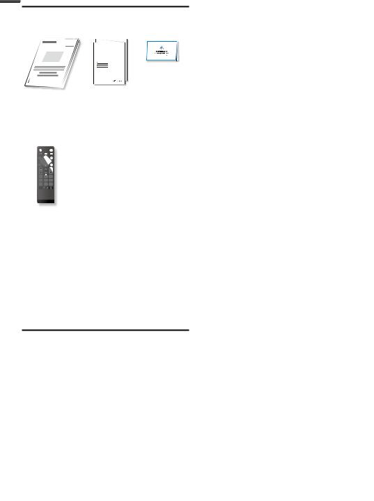
Supplied Accessories
Owner’s Manual Quick Start Guide Registration card
Quick
Start
Installation
Installation
Instalación
TV base and 3 screws (M4 x 14)
Remote Control
(NH001UD) Batteries
(AAA, 1.5V x 2)
PREV CH |
0 |
. |
AAA
 AAA
AAA
Note
If you lose the screws, please purchase M4×14 Phillips head screws at your local store.
If you need to replace these accessories, please refer to the part name or No. with the illustrations and call our toll free customer support line found on the cover of this manual.
When using a universal remote control to operate this unit.
Make sure the component code on your universal remote control is set to our brand. Refer to the manual accompanying your remote control for more details.
We do not guarantee 100% interoperability with all universal remote controls.
Symbols Used in this Manual
The following is the description for the symbols used in this manual. Description refers to:
ATSC : Digital TV operation
NTSC : Analog / Cable TV operation
If neither symbol appears, the operation is applicable to both.
Attaching the Base
You must attach the base to the unit to have it as a table top unit. Be sure the front and rear of the base match the proper direction. At least 2 people are required for these steps.
1 Check the text “FRONT” with “arrow“ on the Base’s bottom to ensure it is being installed in the correct direction. Spread a thick and soft cloth over a table as shown at step 2. Place the main unit face down onto it. Make sure not to damage the screen.
2 |
Insert 2 hooks under the |
|
|
bottom of the main unit |
|
|
into base holes (shown by |
|
|
arrow ), then move the |
|
|
base in the direction as |
|
|
shown by arrow until |
|
|
|
|
|
it stops and the screw |
FRONT |
|
holes are aligned. |
|
|
Make sure not to put the AC power cord between the |
|
|
base and the unit. |
|
3 |
Drive Phillips head screws |
|
|
into the 3 threaded holes |
|
|
at the bottom of the base |
|
|
until they are tight. |
|
To remove the base from this unit
Unscrew the Phillips head screws in step 3
After the screws are removed, pull the base up toward the rear of the unit. Be careful not to drop the base when you remove it.
Note
When attaching the base, ensure that all screws are tightly fastened. If the base is not properly attached, it could cause the unit to fall, resulting in injuries as well as damage to the unit.
Make sure to use a table which can support the weight of this unit and is larger than this unit.
Make sure the table is in a stable location.
When attaching the base, ensure that “FRONT” with “arrow” written on the bottom of the base is downward. If it’s not downward, the 2 hooks don’t fit into the base.
Mounting the Unit on Your Furniture
Screw this unit on your furniture tightly using wood screw (not supplied) in the hole at the back of the base as shown.
Recommended screw dimension : 3/16 x 3/4 inches(5.1 x 20 mm)
rear of this unit
screw hole
Note
When you remove this unit make sure to unscrew the wood screw from your Wood Stand, Furniture and other wood item.
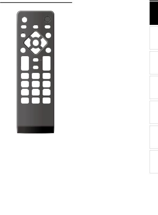
Remote Control Function
1 |
|
SOURCE |
|
11 |
2 |
SLEEP |
FREEZE |
FORMAT |
12 |
|
|
|
||
|
BACK |
|
ECO |
13 |
3 |
|
|
|
14 |
4 |
|
OK |
|
|
|
MENU |
|
INFO |
|
5 |
|
|
|
15 |
6 |
|
SAP |
|
16 |
|
|
|
|
|
7 |
VOL |
MUTE |
CH |
17 |
|
|
|||
8 |
|
|
|
|
|
1 |
2 |
3 |
|
9 |
4 |
5 |
6 |
|
|
7 |
8 |
9 |
|
10 |
PREV CH |
0 |
. |
|
|
|
|
English |
|
1 |
|
SOURCE |
p.12 |
|
2 |
|
SLEEP |
p.12 |
|
3 |
|
BACK |
p.14 |
|
4 |
|
▲/▼/◄/►(cursor) |
p.11 |
|
5 |
|
MENU |
p.15 |
|
6 |
|
OK |
p.11 |
|
7 |
|
VOL / |
p.12 |
|
8 |
|
MUTE |
p.12 |
|
9 |
|
Number buttons |
p.13 |
|
|
|
(dot) |
|
|
|
|
Press to shift the subchannel from the main channel. |
||
10 |
PREV CH |
p.13 |
||
|
|
Press to return to previously viewed channel. |
||
11 |
|
(power) |
p.11 |
|
|
||||
|
|
Press to turn the unit on and go into standby mode. |
||
|
|
To completely turn off the unit, you must unplug the AC |
||
|
|
power cord. |
|
|
12 |
|
FORMAT |
p.13 |
|
|
|
Press to select aspect ratio available for the TV screen. |
||
13 |
FREEZE |
p.13 |
||
|
|
Press to freeze screen image. |
|
|
14 |
ECO |
p.14 |
||
|
|
Press to reduce power consumption. |
||
15 |
|
INFO |
p.14 |
|
16 |
SAP |
p.12 |
||
17 |
CH ▲/▼ |
p.13 |
||
Installing the Batteries
Install the batteries (AAA, 1.5V x 2) matching the polarity indicated inside battery compartment of the remote control.
Battery Precautions:
•Be sure to follow the correct polarity as indicated in the battery compartment. Reversed batteries may cause damage to the device.
•Do not mix different types of batteries together (e.g. Alkaline and Carbon-Zinc, or rechargeable batteries like ni-cad, ni-mh, etc) or old batteries with fresh ones.
•If the device is not to be used for a long period of time, remove the batteries to prevent damage or injury from possible battery leakage.
•Do not try to recharge batteries; they can overheat and rupture.
7
INFORMATION TIPSUSEFUL DEVICES CONNECTING FUNCTIONS USING TV WATCHING PREPARATION INTRODUCTION
8
Control Panel
 VOLUME
 CHANNEL
 MENU SOURCE
  POWER
POWER
1 2 3 4 5
|
1 |
VOLUME |
|
|
|
p.12 |
|
|
/ |
||||||
|
|
||||||
|
|
Press to adjust the volume up /down or move right |
|||||
|
|
( ) / left ( |
) through the main menu items. |
||||
|
2 |
CHANNEL ▲/▼ |
p.13 |
||||
|
|
Press to select channels or move up (▲) / down (▼) |
|||||
|
|
through the main menu items. |
|
||||
7 |
3 |
MENU |
|
|
|
p.15 |
|
6 |
4 |
SOURCE |
|
|
|
p.12 |
|
|
5 |
|
POWER |
|
|
|
p.11 |
|
|
|
|
|
|||
Press to turn the unit on and go into standby mode.
To completely turn off the unit, you must unplug the AC power cord.
6Infrared sensor window
Receives infrared rays transmitted from the remote control.
7Standby indicator
Lights up red when the unit is in standby mode and flashes when the unit goes into standby mode.
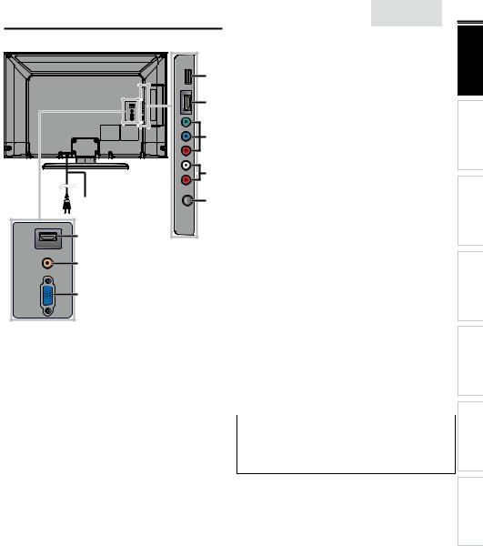
Terminals |
|
|
13 |
HDMI1 |
14 |
|
|
DIGITAL |
15 |
AUDIO OUT |
|
(COAXIAL) |
|
PC-IN |
16 |
RGB |
|
|
|
English |
9 |
|
Side Panel |
|
INTRODUCTION |
|
|
|
|
||
8 |
8 |
USB Terminal |
p.27 |
|
|
Use this terminal only to play back the picture (JPEG) and |
|
||
|
|
video (Motion JPEG) files stored on a USB storage device, |
|
|
9 |
|
or when software update is needed. |
PREPARATION |
|
|
9 |
HDMI 2 Input jack |
p.10, 25 |
|
10 |
10 |
Component/Composite(VIDEO) Video Input jacks |
||
|
|
for VIDEO |
p.26 |
|
|
|
Composite Video Input jack (VIDEO) is shared jack with |
|
|
11 |
|
Component Video Input (Y) jack. |
|
|
11 |
Analog Audio (L/R) Input jacks |
p.10, 25, 26, 27 |
WATCHING |
|
12 |
|
|
||
|
HDMI-DVI /Analog Audio (L/R) jacks signal or |
|||
|
Connect Analog Audio signals from |
|
|
|
|
|
Component Video /Analog Audio (L/R) jacks signal or |
|
|
|
|
Composite Video /Analog Audio (L/R) jacks signal or |
TV |
|
|
|
PC Connection /Analog Audio (L/R) jacks signal with |
|
|
|
|
stereo mini plug conversion cable jack on PC. |
USING |
|
|
|
Analog Audio (L/R) Input jacks are right below the |
||
|
|
|
||
|
|
Component Video Input jacks.When the Audio is |
FUNCTIONS |
|
|
|
monaural, then only connect to the |
Audio L Input jack. |
|
|
|
|
||
|
12 |
Antenna Input jack |
p.10 |
|
|
Rear Panel |
|
|
|
|
13 |
AC power cord |
p.10 |
CONNECTING |
|
14 |
HDMI 1 (HDMI-DVI) Input jack |
p.10, 25 |
|
|
|
|||
|
|
|
|
|
|
15 |
Digital Audio Output jack |
p.26 |
DEVICES |
|
16 |
PC (VGA) Input jack |
p.27 |
|
|
|
|||
Note for USB terminal
•User should not connect any devices to the USB terminal such as digital camera, keyboard, mouse, etc. (because these will not work).
•The software update is, in most cases, handled by an authorized service person or in some circumstances the user may be asked to do the software update themselves.
INFORMATION TIPSUSEFUL
10
PREPARATION
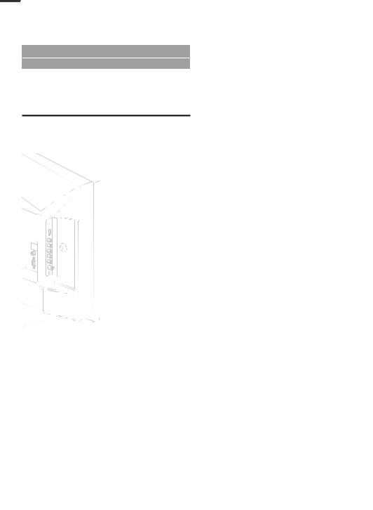
No supplied cables are used with these connections:
• Please purchase the necessary cables at your local store.
Before you connect:
Be sure your antenna or other device is connected properly before plugging in the AC power cord.
Antenna Connection
Connect the RF coaxial cable on your home outlet to the antenna input jack of this unit.
VHF / UHF analog
or
DTV antenna
Connection to Cable Receiver or Satellite Box
Use an HDMI or Component Video cables to connect the HDMI or the Component Video Input jacks of the unit to the HDMI or the Component Video output jacks of the cable receiver / satellite box.
If you connect to the unit’s Component Video Input jacks, connect Analog Audio cables to the Analog Audio L/R Input jacks right below the Component Video connector jacks.
|
satellite dish |
|
cable TV signal |
|
including PPV |
|
or |
or |
RF coaxial cable |
|
|
|
HDMI cable |
or
RF coaxial cable
cable TV signal
Once connections are completed, turn on the unit and begin initial setup. Channel scanning is necessary for the unit to memorize all available channels in your area. [Initial Setup]
p.11
Note
If you have any question about the DTV’s antenna, visit www.antennaweb.org for further information.
Depending on your antenna system, you may need different types of combiners (mixers) or separators (splitters) for HD TV signal the minimum RF bandpass on these devices is 2,000MHz or 2GHz. For your safety and to avoid damage to this unit, please unplug the RF coaxial cable from the antenna input jack before moving the unit.
If you did use an antenna to receive analog TV, it should also work for DTV reception. Outdoor or attic antennas will be more effective than a set top or inside antenna.
To switch your reception source easily between antenna and cable, install an antenna selector.
If you are not receiving a signal from your cable service, contact the Cable provider.
component video cables |
|
(green) (blue) |
(red) |
|
|
(red / blue / green) and |
|
|
|||
|
|
|
|
|
|
audio cables |
|
|
|
|
|
AUDIO OUT |
COMPONENT VIDEO OUT |
HDMI OUT |
|||
L |
R |
Y |
Pb/Cb |
Pr/Cr |
|
|
|
|
|
|
or |
|
|
|
|
|
ANT IN |
|
|
|
|
|
STEREO |
|
|
|
|
|
PCM |
cable receiver / satellite box
You can also connect this unit to the cable receiver or satellite box other than the HDMI or the ComponentVideo output jacks or CompositeVideo output jack ( p.26) because they might have different output jacks.
Required cables and connecting methods of the cable receiver/ satellite box, or the availability channel for the clear QAM may differ depending on the cable/satellite provider or localTV broadcaster.
For more information, please contact your cable/satellite provider or localTV broadcaster.
Note
•Use an HDMI cable with the HDMI logo (a certified HDMI cable). High Speed HDMI cable is recommended for the better compatibility.
Plug In the AC Power Cord
Make sure that the AC power cord must be plugged to an AC outlet after all the necessary connections are made.
Caution:
•Do not connect the AC power cord to a power supply outside the indicated voltage of this unit (AC 120V).
Connecting the AC power cord to a power supply outside of this range may result in fire or electrical shocks.
Note
•Each time you plug in the AC power cord, no operations will be performed for a few seconds.This is not a malfunction.
Loading...