


 Loading...
Reference Manual
IP2030/RM, Rev AA
June 2014
Mobrey MCU900 Series
4–20 mA + HART® Compatible Controller
Reference Manual |
Title Page |
IP2030/RM, Rev AA |
June 2014 |
Mobrey MCU900 Series
Universal Control Unit
Read this manual before working with the product.
For personal and system safety, and for optimum product performance, make sure you thoroughly understand the contents before installing, using, or maintaining this product.
For the latest customer support information, visit the Mobrey brand pages at www.emersonprocess.com, and then click on the Mobrey
Service or Product Support quick links.
The products described in this document are NOT designed for nuclear-qualified applications.
Using non-nuclear qualified products in applications that require nuclear-qualified hardware or products may cause inaccurate readings.
For information on Rosemount nuclear-qualified products, contact an Emerson Process Management Sales Representative.
Replacement equipment or spare parts not approved by Emerson for use as spare parts could reduce the capabilities of the Mobrey MCU900 Series control unit, and may render the instrument dangerous.
Use spare parts supplied or sold by Emerson
1
Reference Manual |
Table of Contents |
IP2030/RM, Rev AA |
June 2014 |
|
|
Table of Contents
Section 1: Introduction
1.1 Safety messages. . . . . . . . . . . . . . . . . . . . . . . . . . . . . . . . . . . . . . . . . . . . . . . . . . . . . . . .1 1.2 Manual overview . . . . . . . . . . . . . . . . . . . . . . . . . . . . . . . . . . . . . . . . . . . . . . . . . . . . . . .2 1.3 Control unit versions and software releases . . . . . . . . . . . . . . . . . . . . . . . . . . . . . . . .2 1.4 Customer support . . . . . . . . . . . . . . . . . . . . . . . . . . . . . . . . . . . . . . . . . . . . . . . . . . . . . .2 1.5 Product recycling/disposal . . . . . . . . . . . . . . . . . . . . . . . . . . . . . . . . . . . . . . . . . . . . . . .2
Section 2: Control Unit Overview
2.1 Safety messages. . . . . . . . . . . . . . . . . . . . . . . . . . . . . . . . . . . . . . . . . . . . . . . . . . . . . . . .3 2.2 About the Mobrey MCU900 Series Control Unit. . . . . . . . . . . . . . . . . . . . . . . . . . . . .3 2.2.1 Wall and panel mounting options. . . . . . . . . . . . . . . . . . . . . . . . . . . . . . . . . .3 2.2.2 4–20mA HART transmitter input options . . . . . . . . . . . . . . . . . . . . . . . . . . .4 2.2.3 Control functionality . . . . . . . . . . . . . . . . . . . . . . . . . . . . . . . . . . . . . . . . . . . . .4 2.3 Control unit functions . . . . . . . . . . . . . . . . . . . . . . . . . . . . . . . . . . . . . . . . . . . . . . . . . . .5 2.3.1 Standard functions . . . . . . . . . . . . . . . . . . . . . . . . . . . . . . . . . . . . . . . . . . . . . .5 2.3.2 Difference, sum, and product functions (on MCU902 only) . . . . . . . . . . .5 2.3.3 Data logging functions (on MCU90F only) . . . . . . . . . . . . . . . . . . . . . . . . . .5 2.4 Control unit front panel . . . . . . . . . . . . . . . . . . . . . . . . . . . . . . . . . . . . . . . . . . . . . . . . .6 2.4.1 Keypad . . . . . . . . . . . . . . . . . . . . . . . . . . . . . . . . . . . . . . . . . . . . . . . . . . . . . . . . .6 2.4.2 Status LED . . . . . . . . . . . . . . . . . . . . . . . . . . . . . . . . . . . . . . . . . . . . . . . . . . . . . .6 2.4.3 Display . . . . . . . . . . . . . . . . . . . . . . . . . . . . . . . . . . . . . . . . . . . . . . . . . . . . . . . . .7
Section 3: Installation
3.1 Safety messages. . . . . . . . . . . . . . . . . . . . . . . . . . . . . . . . . . . . . . . . . . . . . . . . . . . . . . . .9 3.2 Considerations before installation . . . . . . . . . . . . . . . . . . . . . . . . . . . . . . . . . . . . . . 10 3.2.1 Safety considerations . . . . . . . . . . . . . . . . . . . . . . . . . . . . . . . . . . . . . . . . . . .10 3.3 Mounting the control unit . . . . . . . . . . . . . . . . . . . . . . . . . . . . . . . . . . . . . . . . . . . . . 11 3.3.1 Mounting the wall-mount version . . . . . . . . . . . . . . . . . . . . . . . . . . . . . . . .11 3.3.2 Mounting the panel version. . . . . . . . . . . . . . . . . . . . . . . . . . . . . . . . . . . . . .11 3.4 Electrical installation . . . . . . . . . . . . . . . . . . . . . . . . . . . . . . . . . . . . . . . . . . . . . . . . . . 13 3.4.1 Making electrical connections on wall-mount units . . . . . . . . . . . . . . . . .13 3.4.2 Making electrical connections on panel-mount units. . . . . . . . . . . . . . . .15 3.4.3 Power connections . . . . . . . . . . . . . . . . . . . . . . . . . . . . . . . . . . . . . . . . . . . . .16 3.4.4 Earthing connections . . . . . . . . . . . . . . . . . . . . . . . . . . . . . . . . . . . . . . . . . . .16
Table of Contents |
TOC-i |
Table of Contents |
Reference Manual |
June 2014 |
IP2030/RM, Rev AA |
|
|
3.4.5 Transmitter connections and cabling. . . . . . . . . . . . . . . . . . . . . . . . . . . . . .16 3.4.6 Connecting HART transmitters to the Mobrey MCU902 . . . . . . . . . . . . .18 3.4.7 Relay connections . . . . . . . . . . . . . . . . . . . . . . . . . . . . . . . . . . . . . . . . . . . . . .20 3.4.8 Current output connections . . . . . . . . . . . . . . . . . . . . . . . . . . . . . . . . . . . . .20 3.4.9 Digital control voltage-free contact inputs. . . . . . . . . . . . . . . . . . . . . . . . .21 3.4.10 RS232 connections . . . . . . . . . . . . . . . . . . . . . . . . . . . . . . . . . . . . . . . . . . . . .22
Section 4: Getting started
4.1 Safety messages. . . . . . . . . . . . . . . . . . . . . . . . . . . . . . . . . . . . . . . . . . . . . . . . . . . . . . 25 4.2 Switching on the MCU901 and MCU90F for the first time . . . . . . . . . . . . . . . . . . 26 4.2.1 Switching on with one new HART transmitter connected . . . . . . . . . . . .27 4.2.2 Switching on with one 4–20 mA transmitter connected . . . . . . . . . . . . .29 4.3 Switching on the MCU902 for the first time . . . . . . . . . . . . . . . . . . . . . . . . . . . . . . 29 4.4 A quick tour of the menu system . . . . . . . . . . . . . . . . . . . . . . . . . . . . . . . . . . . . . . . 30 4.5 Programming the control unit. . . . . . . . . . . . . . . . . . . . . . . . . . . . . . . . . . . . . . . . . . 32 4.5.1 The basics . . . . . . . . . . . . . . . . . . . . . . . . . . . . . . . . . . . . . . . . . . . . . . . . . . . . .32 4.5.2 Step-by-step programming of the control unit . . . . . . . . . . . . . . . . . . . . .37 4.5.3 Run App and Program operating modes . . . . . . . . . . . . . . . . . . . . . . . . . . .38 4.5.4 Application Wizard . . . . . . . . . . . . . . . . . . . . . . . . . . . . . . . . . . . . . . . . . . . . .39 4.5.5 Optional change: system settings . . . . . . . . . . . . . . . . . . . . . . . . . . . . . . . .42
4.5.6Optional change:
transmitter input channel settings (advanced users) . . . . . . . . . . . . . . . .43
4.5.7Programming Input Channel 1 for a 4–20 mA input
(advanced users) . . . . . . . . . . . . . . . . . . . . . . . . . . . . . . . . . . . . . . . . . . . . . . .44 4.5.8 Programming Channel 1 for a HART input (advanced users). . . . . . . . . .48
4.5.9Programming Channel 2 for a HART input (MCU902 only)
(advanced users) . . . . . . . . . . . . . . . . . . . . . . . . . . . . . . . . . . . . . . . . . . . . . . .50
4.5.10 Volumetric contents and flow measurement applications
(advanced users) . . . . . . . . . . . . . . . . . . . . . . . . . . . . . . . . . . . . . . . . . . . . . . .52
4.5.11 Set-up the volumetric contents calculations for a
popular linear / uniform vessel (advanced users). . . . . . . . . . . . . . . . . . . .52
4.5.12 Set-up the volumetric contents calculations for a popular
non-linear / non-uniform shaped vessel (advanced users). . . . . . . . . . . .53
4.5.13 Set-up flow calculations for non-linear / non-uniform
open channel profiles (advanced users) . . . . . . . . . . . . . . . . . . . . . . . . . . .56
4.5.14 Set-up open channel flow calculations for pre-programmed flat, parabolic, and Parshall flumes (advanced users) . . . . . . . . . . . . . . . . . . . .58
4.5.15 Set-up Kindsvater Shen (V-notch ISO1438) flow calculations. . . . . . . . .59 4.5.16 Set-up exponential flow law calculations . . . . . . . . . . . . . . . . . . . . . . . . . .59
TOC-ii |
Table of Contents |
Reference Manual |
Table of Contents |
IP2030/RM, Rev AA |
June 2014 |
|
|
4.5.17 Using a plotted profile for calculating volume or flow . . . . . . . . . . . . . . .61 4.5.18 Digital inputs IN1 and IN2. . . . . . . . . . . . . . . . . . . . . . . . . . . . . . . . . . . . . . . .63 4.5.19 Data logging on the Mobrey MCU90F . . . . . . . . . . . . . . . . . . . . . . . . . . . . .64 4.5.20 Set-up the current output . . . . . . . . . . . . . . . . . . . . . . . . . . . . . . . . . . . . . . .68 4.5.21 Set-up the relays . . . . . . . . . . . . . . . . . . . . . . . . . . . . . . . . . . . . . . . . . . . . . . .69 4.5.22 Set-up alarms . . . . . . . . . . . . . . . . . . . . . . . . . . . . . . . . . . . . . . . . . . . . . . . . . .91 4.5.23 Set-up totalizing on the Mobrey MCU901 control unit. . . . . . . . . . . . . . .95 4.5.24 Set-up totalizing on the Mobrey MCU902 control unit. . . . . . . . . . . . . . .97 4.5.25 Set-up totalizing on the Mobrey MCU90F control unit. . . . . . . . . . . . . . .99 4.5.26 Display configuration options . . . . . . . . . . . . . . . . . . . . . . . . . . . . . . . . . . 102 4.5.27 Serial communications . . . . . . . . . . . . . . . . . . . . . . . . . . . . . . . . . . . . . . . . 104 4.5.28 PIN Security. . . . . . . . . . . . . . . . . . . . . . . . . . . . . . . . . . . . . . . . . . . . . . . . . . 105
Section 5: Servicing and Health Checking
5.1 Safety messages. . . . . . . . . . . . . . . . . . . . . . . . . . . . . . . . . . . . . . . . . . . . . . . . . . . . . 107 5.2 Servicing the MCU900 Series control unit . . . . . . . . . . . . . . . . . . . . . . . . . . . . . . . 107 5.2.1 Replacing the fuse on mains ac-powered control units . . . . . . . . . . . . 108 5.3 Health checking the MCU900 Series control unit . . . . . . . . . . . . . . . . . . . . . . . . 110 5.3.1 Simulation (self-test). . . . . . . . . . . . . . . . . . . . . . . . . . . . . . . . . . . . . . . . . . 110 5.3.2 Display test . . . . . . . . . . . . . . . . . . . . . . . . . . . . . . . . . . . . . . . . . . . . . . . . . . 110 5.3.3 Calibration of the Current Input (Iin). . . . . . . . . . . . . . . . . . . . . . . . . . . . . 111 5.3.4 Fixing the Current Output (Iout). . . . . . . . . . . . . . . . . . . . . . . . . . . . . . . . . 111 5.3.5 Calibration of the Current Output (Iout). . . . . . . . . . . . . . . . . . . . . . . . . . 112 5.3.6 Monitoring the control unit readings. . . . . . . . . . . . . . . . . . . . . . . . . . . . 112 5.3.7 Diagnostic data for the MCU900 Series control unit. . . . . . . . . . . . . . . 115 5.3.8 Model code, serial number, and software and hardware revisions. . . 116
Appendix A: Reference Data
A.1 Specifications . . . . . . . . . . . . . . . . . . . . . . . . . . . . . . . . . . . . . . . . . . . . . . . . . . . . . . . 117
A.1.1 General . . . . . . . . . . . . . . . . . . . . . . . . . . . . . . . . . . . . . . . . . . . . . . . . . . . . . 117
A.1.2 Display . . . . . . . . . . . . . . . . . . . . . . . . . . . . . . . . . . . . . . . . . . . . . . . . . . . . . . 117
A.1.3 Electrical . . . . . . . . . . . . . . . . . . . . . . . . . . . . . . . . . . . . . . . . . . . . . . . . . . . . 117
A.1.4 Mechanical . . . . . . . . . . . . . . . . . . . . . . . . . . . . . . . . . . . . . . . . . . . . . . . . . . 119
A.1.5 Environment . . . . . . . . . . . . . . . . . . . . . . . . . . . . . . . . . . . . . . . . . . . . . . . . . 119
A.2 Dimensional drawings. . . . . . . . . . . . . . . . . . . . . . . . . . . . . . . . . . . . . . . . . . . . . . . . 121
Table of Contents |
TOC-iii |
Table of Contents |
Reference Manual |
June 2014 |
IP2030/RM, Rev AA |
|
|
Appendix B: Product Certifications
B.1 Safety messages. . . . . . . . . . . . . . . . . . . . . . . . . . . . . . . . . . . . . . . . . . . . . . . . . . . . . 123
B.2 European directive information. . . . . . . . . . . . . . . . . . . . . . . . . . . . . . . . . . . . . . . . 124
B.3 Hazardous locations certifications . . . . . . . . . . . . . . . . . . . . . . . . . . . . . . . . . . . . . 124
B.3.1 ATEX intrinsically safe approvals . . . . . . . . . . . . . . . . . . . . . . . . . . . . . . . . 124
B.3.2 IECEx intrinsically safe approvals. . . . . . . . . . . . . . . . . . . . . . . . . . . . . . . . 124
Appendix C: Menus and Parameters
C.1 Menus and parameters . . . . . . . . . . . . . . . . . . . . . . . . . . . . . . . . . . . . . . . . . . . . . . . 125
Appendix D: Additional Features
D.1 Restoring the factory defaults . . . . . . . . . . . . . . . . . . . . . . . . . . . . . . . . . . . . . . . . . 135
D.1.1 How to restore the factory default settings . . . . . . . . . . . . . . . . . . . . . . 135
D.2 ADVANCED parameter access . . . . . . . . . . . . . . . . . . . . . . . . . . . . . . . . . . . . . . . . . 136
Appendix E: Support for HART® Transmitters
E.1 Overview . . . . . . . . . . . . . . . . . . . . . . . . . . . . . . . . . . . . . . . . . . . . . . . . . . . . . . . . . . . 139
E.2 Fully supported HART transmitters. . . . . . . . . . . . . . . . . . . . . . . . . . . . . . . . . . . . . 139
E.3 Generic support for HART transmitters . . . . . . . . . . . . . . . . . . . . . . . . . . . . . . . . . 139
E.3.1 Compatibility between transmitter and control unit . . . . . . . . . . . . . . 139
E.3.2 Universal and common practice commands . . . . . . . . . . . . . . . . . . . . . 140
Index
TOC-iv |
Table of Contents |

Reference Manual |
Section 1: Introduction |
IP2030/RM, Rev AA |
June 2014 |
Section 1 Introduction
Safety messages . . . . . . . . . . . . . . . . . . . . . . . . . . . . . . . . . . . . . . . . . . . . . . . . . . . . . . . . . page 1 Manual overview . . . . . . . . . . . . . . . . . . . . . . . . . . . . . . . . . . . . . . . . . . . . . . . . . . . . . . . . page 2 Control unit versions and software releases . . . . . . . . . . . . . . . . . . . . . . . . . . . . . . . . page 2 Customer support . . . . . . . . . . . . . . . . . . . . . . . . . . . . . . . . . . . . . . . . . . . . . . . . . . . . . . . page 2 Product recycling/disposal . . . . . . . . . . . . . . . . . . . . . . . . . . . . . . . . . . . . . . . . . . . . . . . . page 2
1.1Safety messages
Procedures and instructions in this manual may require special precautions to ensure the safety of the personnel performing the operations. Information that raises potential safety issues is indicated by a caution symbol ( ). The external hot surface symbol (
 ) is used when a surface is hot and care must be taken to avoid possible burns. If there is a risk of an electrical shock the (
 ) symbol is used. Refer to the safety messages listed at the beginning of each section before performing an operation preceded by this symbol.
Failure to follow these installation guidelines could result in death or serious injury:
The Mobrey MCU900 Series Control Unit must be installed, connected, commissioned, operated, and maintained by suitably qualified personnel only, observing any national and local requirements that may apply
Use the equipment only as specified in this manual. Failure to do so may impair the protection provided by the equipment
Explosions could result in death or serious injury:
Please review the approvals section of this reference manual for any restrictions associated with an installation
Electrical shock could cause death or serious injury:
If the control unit is installed in a high voltage environment and a fault condition or installation error occurs, high voltage may be present on leads and terminals
Use extreme caution when making contact with the leads and terminals
Make sure that power to the control unit is off while making connections
Section 1: Introduction |
1 |

Section 1: Introduction |
Reference Manual |
June 2014 |
IP2030/RM, Rev AA |
1.2Manual overview
This manual provides installation, configuration and maintenance information for the
Mobrey MCU900 Series control unit.
Section 2: Control Unit Overview
Section 3: Installation
Section 4: Getting started
Section 5: Servicing and Health Checking
Appendix A: Reference Data
Appendix B: Product Certifications
Appendix C: Menus and Parameters
Appendix D: Additional Features
Appendix E: Support for HART® Transmitters
1.3Control unit versions and software releases
The following control unit versions are covered in this product manual:
Mobrey MCU901 Standard Control Unit
Mobrey MCU902 Differential Control Unit
Mobrey MCU90F Logging Control Unit
The software release covered in this product manual is issue 4.00.00 (and above).
1.4Customer support
For the latest customer support information, visit the Mobrey brand pages at www.emersonprocess.com, and then click on the Mobrey Service or Product Support
quick links.
1.5Product recycling/disposal
Recycling of equipment and packaging should be taken into consideration. The product and packaging should be disposed of in accordance with local and national legislation.
2 |
Section 1: Introduction |
Reference Manual |
Section 2: Control Unit Overview |
IP2030/RM, Rev AA |
June 2014 |
Section 2 Control Unit Overview
Safety messages . . . . . . . . . . . . . . . . . . . . . . . . . . . . . . . . . . . . . . . . . . . . . . . . . . . . . . . . . |
page 3 |
About the Mobrey MCU900 Series Control Unit . . . . . . . . . . . . . . . . . . . . . . . . . . . . . . |
page 3 |
Control unit functions . . . . . . . . . . . . . . . . . . . . . . . . . . . . . . . . . . . . . . . . . . . . . . . . . . . . |
page 5 |
Control unit front panel . . . . . . . . . . . . . . . . . . . . . . . . . . . . . . . . . . . . . . . . . . . . . . . . . . |
page 6 |
|
|
2.1Safety messages
Procedures and instructions in this manual may require special precautions to ensure the safety of the personnel performing the operations. Information that raises potential safety issues is indicated by a caution symbol ( ). The external hot surface symbol (
 ) is used when a surface is hot and care must be taken to avoid possible burns. If there is a risk of an electrical shock the (
 ) symbol is used. Refer to the safety messages listed at the beginning of each section before performing an operation preceded by this symbol.
2.2About the Mobrey MCU900 Series Control Unit
Note
A full specification for the control unit is in Appendix A: Reference Data.
2.2.1Wall and panel mounting options
The wall mounting option has a tough, weatherproof enclosure for internal or external installation.
The panel mounting option has a black enclosure, and is designed for control room panel or cabinet installation.
Figure 2-1. Mounting options
Wall Mount |
Panel Mount |
Section 2: Control Unit Overview |
3 |
Section 2: Control Unit Overview |
Reference Manual |
June 2014 |
IP2030/RM, Rev AA |
2.2.24–20mA HART transmitter input options
4–20mA HART transmitter input options:
The Mobrey MCU901 Standard control unit and the Mobrey MCU90F Logging control unit accepts one 4–20mA or HART transmitter input
The Mobrey MCU902 Differential control unit accepts two HART transmitter inputs
Note
The Mobrey MCU900 Series is designed for non-hazardous (safe) area installation, but can be connected to a transmitter installed in a hazardous area.
See Appendix B: Product Certifications for the control unit certifications.
2.2.3Control functionality
Control functionality is provided by five SPDT voltage-free contact relays in the control unit (see Figure 2-2 on page 4). The five relay outputs are fully field adjustable to perform a wide variety of control, fault indication, or alarm duties.
For applications where the control unit functionality is linked to other external events, there are two digital input ports for accepting contact closure signals.
The isolated 4–20 mA signal output from the Current Output of the control unit is driven by a Primary / Process Value (PV) e.g. level.
Figure 2-2. Typical application using a Mobrey MCU900 Series control unit
B
A |
|
|
|
G |
|
|
|
C |
|
D |
D |
20mA |
|
|
E |
E |
|
F |
|
|
4mA |
|
|
A. Mobrey MSP Series Level Transmitter |
E. Pump |
|
B. Mobrey MCU900 Series Control Unit |
F. Transmitter Bottom Reference |
|
C. 4–20 mA signal output |
G. 4–20 mA and HART signal input |
|
D. Relay |
|
|
4 |
Section 2: Control Unit Overview |

Reference Manual |
Section 2: Control Unit Overview |
IP2030/RM, Rev AA |
June 2014 |
2.3Control unit functions
2.3.1Standard functions
The Mobrey MCU900 Series control unit provides these standard functions:
Calculation and display of the control unit Primary / Process Value (PV)
The control unit PV is typically a live transmitter reading, which can be any measured value e.g. level, temperature, or pressure.
Alternatively, the control unit PV is a volume or flow value calculated using the live transmitter level reading. The control unit is pre-programmed with standard tank shapes and flow algorithms to simplify the configuration for calculating volume or flow from the live transmitter level reading. A 20-point programmable look-up table is provided for non-standard applications.
Output of measured variable as an isolated 4–20mA signal
The output signal is driven by the control unit Primary / Process Value (PV).
Relay control functions
There are five freely assignable relay outputs. By default, Relay 5 is a fault relay but can be assigned to a control duty. The other relays are available to operate at user-entered PV values.
The control unit is pre-programmed with popular pump control routines for wet well and sump control, along with energy saving overrides.
Voltage-free (digital) contact closure inputs
There are two digital input ports for accepting contact closure signals to override control unit functions.
HART transmitter interrogation and programming
Any HART transmitter can be connected. The control unit recognizes the transmitter as an “unknown instrument” but supports the Universal and Common Practice HART commands (see Appendix E: Support for HART® Transmitters).
When a Mobrey MSP Series HART transmitter is connected, the control unit recognizes the transmitter and allows full access to the transmitter’s configuration parameters. Refer to the reference manual of the transmitter for full information about programming the transmitter parameters (e.g. Transmitter Bottom Reference) using the MCU900 Series control unit or other HART-based devices.
2.3.2Difference, sum, and product functions (on MCU902 only)
The Mobrey MCU902 Differential control unit has all the functions of the standard control unit, plus extra functions for calculating the difference, sum, or product of two separate inputs from HART transmitters.
2.3.3Data logging functions (on MCU90F only)
The Mobrey MCU90F Logging control unit has all the functions of the standard control unit, plus a 7000 event logging function.
Section 2: Control Unit Overview |
5 |
Section 2: Control Unit Overview |
Reference Manual |
June 2014 |
IP2030/RM, Rev AA |
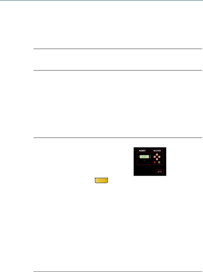
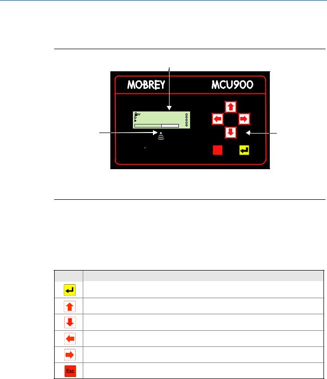
2.4Control unit front panel
This front panel fascia has an integral keypad, display, and health status LED.
Figure 2-3. Front panel fascia
A
|
12:47 |
RL1 |
IN1 |
1.572 m |
RL2 |
IN2 |
RL4 |
|
|
|
RL3 |
|
MCU |
RL5 |
|
|
B |
C |
Esc |
A.4-line Back-lit LCD Display
B.Status LED
C.Keypad
2.4.1Keypad
The membrane keypad has six function buttons (Table 2-1). The buttons are used for navigating a menu system and for viewing or changing application parameters.
Table 2-1. Keypad Function Buttons
Button What the button will do
When the Primary / Process Value (PV) is shown, use the red (ENTER) button to access the menu system.
At other times, this button is for selecting a menu option and for confirming something.
When navigating the menu system, the UP-ARROW button is for moving upwards one line.
At other times, this button is for scrolling through a list of alphanumeric characters or a list of options.
When navigating the menu system, the DOWN-ARROW button is for moving downwards one line.
At other times, this button is for scrolling through a list of alphanumeric characters or a list of options.
The LEFT-ARROW button is for moving left e.g. to another character when editing a parameter value.
The RIGHT-ARROW button is for moving right e.g. to another character when editing a parameter value.
When navigating the menu system, use the ESCAPE button to return to a previous menu level and the
Full PV Display. At other times, e.g. while editing, the button is for restoring a setting that is being edited.
2.4.2Status LED
The LED is positioned just below the LCD (Figure 2-3 on page 6). It flashes once per second to indicate that the control unit and transmitters are operating correctly. The LED is constantly lit if there are operating difficulties e.g. a transmitter fault.
6 |
Section 2: Control Unit Overview |
Reference Manual |
Section 2: Control Unit Overview |
IP2030/RM, Rev AA |
June 2014 |
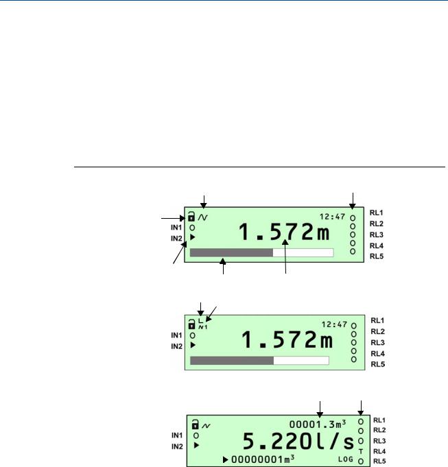
2.4.3Display
After the power-up and self-checks are completed, the Full PV Display is presented.
The default Full PV Display typically features a digital clock, a measured variable with display units, and status icons. There are some display differences between control units:
On the MCU901 and MCU902, a bar graph indicates the 4–20mA output signal. (The MCU90F display can be changed to show the bar graph).
On the MCU902, an extra icon on the first line and indicates if one or two HART transmitters connected to the control unit.
On the MCU90F, there are two totalizers displayed; one above and one below the control unit Primary / Process Value (PV).
Figure 2-4. Typical displays of the MCU901, MCU902, and MCU90F
B C
Mobrey MCU901
A
F
E |
D |
G |
|
H |
Mobrey MCU902 |
|
K I
Mobrey MCU90F
J |
|
|
|
|
|
||
A. Program/Run App mode (locked padlock = Run App mode) |
H. HART Transmitter Communicating |
||
B. HART Transmitter Communicating (absent if Idle) |
(1=Tx1, 2=Tx2) |
||
C. Relay (RL) Status: O = De-energized, = Energized, |
I. Relay (RL) Status: O = De-energized, = Energized, |
||
A = Alarm, S = Sampler, T = Totalizer |
A = Alarm, S = Sampler, T = Totalizer |
||
D.Primary / Process Value (PV) of Control Unit |
J. Totalizer 1 |
||
E. Bar graph of 4–20mA Output |
K. Totalizer 2 (Daily Total) |
||
F. Digital Input Status: O = Open, = Closed |
|
||
G. HART Transmitter Allocated: |
|
||
Left Vertical Bar = Tx1; Right Vertical Bar = Tx2 |
|
||
|
|
|
|
Section 2: Control Unit Overview |
7 |
Section 2: Control Unit Overview |
Reference Manual |
June 2014 |
IP2030/RM, Rev AA |
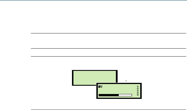
After a period of keypad inactivity, the display automatically changes to the Large PV Display. This shows only the control unit Primary / Process Value (PV) and Display units, but in a larger character size to facilitate easier viewing.
To restore the Full PV Display, press the red (ENTER) button.
Note
The Large PV Display feature can be switched off using parameter P574. See “Display configuration options” on page 102.
Figure 2-5. Large PV Display
Large PV Display
1.572 m 


1 |
12:47 |
 1.572 m
Full PV Display
8 |
Section 2: Control Unit Overview |
Reference Manual |
Section 3: Installation |
IP2030/RM, Rev AA |
June 2014 |
Section 3 Installation
Safety messages . . . . . . . . . . . . . . . . . . . . . . . . . . . . . . . . . . . . . . . . . . . . . . . . . . . . . . . . . page 9 Considerations before installation . . . . . . . . . . . . . . . . . . . . . . . . . . . . . . . . . . . . . . . . . page 10 Mounting the control unit . . . . . . . . . . . . . . . . . . . . . . . . . . . . . . . . . . . . . . . . . . . . . . . . page 11 Electrical installation . . . . . . . . . . . . . . . . . . . . . . . . . . . . . . . . . . . . . . . . . . . . . . . . . . . . . page 13
3.1Safety messages
Procedures and instructions in this manual may require special precautions to ensure the safety of the personnel performing the operations. Information that raises potential safety issues is indicated by a caution symbol ( ). The external hot surface symbol (
 ) is used when a surface is hot and care must be taken to avoid possible burns. If there is a risk of an electrical shock the (
 ) symbol is used. Refer to the safety messages listed at the beginning of each section before performing an operation preceded by this symbol.
Failure to follow these installation guidelines could result in death or serious injury:
The Mobrey MCU900 Series control unit must be installed, connected, commissioned, operated, and maintained by suitably qualified personnel only, observing any national and local requirements that may apply
Use the equipment only as specified in this manual. Failure to do so may impair the protection provided by the equipment
Explosions could result in death or serious injury:
Please review the approvals section of this reference manual for any restrictions associated with an installation
Electrical shock could cause death or serious injury:
If the control unit is installed in a high voltage environment and a fault condition or installation error occurs, high voltage may be present on leads and terminals
Use extreme caution when making contact with the leads and terminals
Make sure that power to the control unit is off while making connections
Section 3: Installation |
9 |

Section 3: Installation |
Reference Manual |
June 2014 |
IP2030/RM, Rev AA |
3.2Considerations before installation
Note
The Mobrey MCU900 Series is designed for non-hazardous (safe) area installation, but can power and take input from an intrinsically safe transmitter installed in a hazardous area. See Appendix B: Product Certifications for the control unit certifications.
3.2.1Safety considerations
Guidelines
1.This product is classified type A in accordance with European EMC directive 2004/108/EC. To ensure electro-magnetic compatibility, in any member country, this product should not be installed in a residential area.
2.Do not mount the control unit on a structure that is subject to vibration, or in a position where damage may be caused by impact, thermal stress or liquid ingress.
3.The fuse must only be replaced with the type specified (see page 108 for procedure).
4.If the equipment is likely to come into contact with aggressive substances, it is the responsibility of the user to take suitable precautions that prevent it from being adversely affected, thus ensuring that the type of protection is not compromised.
Aggressive Substances - e.g. acidic liquids or gases that may attack metals or solvents that may affect polymeric materials.
Suitable Precautions - e.g. regular checks as part of routine inspections or establishing from the material's data sheet that it is resistant to specific chemicals.
5.The user should not repair this equipment.
6.Terminal 30 (intrinsically safe earth/ground) of the control unit must be connected to a high integrity earth/ground point.
7.A mains powered Control Unit must not be connected to a supply exceeding 250 V r.m.s. or dc, or to apparatus containing a source of voltage exceeding 250 V r.m.s. or dc.
8.A direct current (dc) powered control unit must not be connected to a supply exceeding 30 Vdc or apparatus containing a source of voltage exceeding 30 Vdc.
9.The intrinsically safe outputs of the control unit may be connected to certified equipment used in a hazardous area. Refer to Appendix B: Product Certifications for details of relevant certifications.
10.Cable between the MCU900 Series control unit and a transmitter should be shielded, twisted-pair with the shield connected to terminal 3 (marked with earth symbol) on the MCU900 Series control unit. The shield should be left unconnected at the transmitter unless there is a terminal specifically provided for this purpose.
11.Cable runs should be separate from any high voltage or mains cables to avoid crosstalk or interference.
12.Refer to the technical data in Appendix A: Reference Data.
10 |
Section 3: Installation |

Reference Manual |
Section 3: Installation |
IP2030/RM, Rev AA |
June 2014 |
3.3Mounting the control unit
3.3.1Mounting the wall-mount version
Guidelines
This housing is rated IP65. It is suitable for mounting outside, but this should be above any flood level, away from any overflow path, and away from direct sunlight
Do not mount the control unit on a structure that is subject to vibration, or in a position where damage may be caused by impact, thermal stress, or liquid ingress
The mass of the mains powered unit is 1.4 kg, and the DC powered unit is 1.0 kg.
To conform with safety requirements, the wall on which the unit is mounted should be capable of supporting four times this weight
It is not necessary, or advisable, to remove the upper part of the unit housing that contains the LCD and keypad. There are no user serviceable parts inside. The unit must not be modified in any way
Procedure
1.Mount the unit on a suitable wall or structure using the fixing points shown on Figure A-1 on page 121.
2.Make the electrical connections
(see “Making electrical connections on wall-mount units” on page 13).
3.3.2Mounting the panel version
Guidelines
This housing is rated IP40 and is designed for panel mounting in a weatherproof
environment. An optional fascia overlay hood is available which improves the IP rating to IP65 – see Product Data Sheet IP2031 on the Mobrey brand pages at www.emersonprocess.com for ordering information
Do not mount the control unit on a structure that is subject to vibration, or in a position where damage may be caused by impact, thermal stress, or liquid ingress
Where three of more units are fitted in the same cabinet or panel, ensure that there is adequate air circulation to aid cooling. It is recommended that an air circulation fan be fitted
The unit requires at least 6.5 in. (165 mm) clearance behind the mounting panel to avoid cable fouling
After mounting the control unit, all wiring is made at the rear of the unit using the two part terminal blocks provided. (A pre-wired data download socket suitable for front panel mounting is provided on the MCU90F)
Mount the control unit on a panel with thickness 1.5 to 10 mm, ensuring the panel is strong enough to support the 2.6 lb. (1.2 kg) weight of the unit
Ensuring there is enough clearance behind the chosen position in the panel (6.5 in [165 mm] minimum), cut a horizontal slot 5.43 in. (138 mm) long by 2.68 in. (68 mm) high in the panel and remove any rough edges
Section 3: Installation |
11 |
Section 3: Installation |
Reference Manual |
June 2014 |
IP2030/RM, Rev AA |
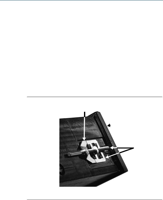
Procedure
1.Unpack the two screw clips provided.
2.Identify the moulded lugs (protrusions) in the recesses on each side of the control unit. (Ignore the recesses on the top and bottom of the unit).
3.Holding the screwdriver-slot-end of the threaded spindle of one of the screw clamps and looking at the control unit rear, engage a screw clamp frame onto the control unit side (see Figure 3-1 on page 12) and see how the four steel lugs (protrusions) of the screw clamp frame engage with the moulded lugs of the unit. Gently pull the screw clamp for the lugs to engage with each other.
4.Remove the screw clamps from both of the screw clamp frames.
5.Slide the control unit into the panel, ensuring that the panel seal provided is in place behind the front panel bezel.
6.Re-fit the screw clamps, one on each side, and tighten with a screwdriver to clamp the control unit against the panel.
7.For electrical connections,
see “Making electrical connections on panel-mount units” on page 15.
Figure 3-1. The fitted screw clamp
A
 B
B
C
A.Screw Clamp Frame
B.Front Panel Bezel
C.Screw Clamp With Threaded Spindle
12 |
Section 3: Installation |
Reference Manual |
Section 3: Installation |
IP2030/RM, Rev AA |
June 2014 |
3.4Electrical installation
It is the responsibility of the installer to:
Refer to safety data and electrical specifications in Appendix A: Reference Data
Refer to the certifications and control drawings in Appendix B: Product Certifications
Check and obtain any work permits required before applying power to the unit
Observe all local regulations and approval requirements
Ensure the wiring is suitable for the load current
Ensure the wiring insulation is suitable for the voltage, temperature, and environment of the installation
Ensure suitable cable glands or conduit connections are used when wiring to the control unit to maintain enclosure integrity
Never remove or modify the mechanical barriers separating the terminal area from the main enclosure and separating the transmitter input terminals from other terminals.
3.4.1Making electrical connections on wall-mount units
All field wiring connections are accessible by removing the lower terminal cover, which is secured by two screws on the wall-mount control unit.
The cabling between the Mobrey MCU900 Series control unit and a transmitter should be a screened (shielded), twisted-pair type with the cable screen (shield) connected to terminal 3 (marked with earth/ground symbol) on the Mobrey MCU900 Series control unit. The cable screen (shield) should be left unconnected at the transmitter end unless there is a terminal specifically provided for this purpose.
Cable runs should be separate from any high voltage or mains cables to avoid crosstalk or interference.
Figure 3.4.2 on page 15 shows the layout of the control unit terminals. All terminal blocks are suitable for wires 14 to 26 AWG (0,5 to 1,5 mm ), except the mains terminals which are suitable for wires 10 AWG (2,5 mm ). Insulation should be stripped back 1/4 in. (7 mm).
Transmitter connections are made on the left side of the terminals enclosure. The intrinsically safe earth/ground (terminal 30) must be connected to a high integrity earth/ground point if the transmitter connected to terminals 1 and 2 is sited in a hazardous area.
Note
Use only 167 F (75 C) copper conductors for field wiring.
Note
In intrinsically safe systems, apparatus connected to the MCU900 Series control unit must not be supplied from a voltage greater than 250V r.m.s. or 250 Vdc.
Section 3: Installation |
13 |
Section 3: Installation |
Reference Manual |
||
June 2014 |
IP2030/RM, Rev AA |
||
|
|
|
|
|
|
|
|
Figure 3-2. Connection terminals layout (for mains-powered wall-mount unit)
|
|
|
|
4 |
5 |
6 |
|
|
|
|
|
|
|
|
|
|
|
|
|
1 |
2 |
3 |
|
7 |
8 |
9 |
13 |
14 |
15 |
19 |
20 |
21 |
|||||||
24V |
Iin |
|
|
RX TX |
0V |
24V Iout |
0V |
NO COM NC |
NO COM NC |
||||||||||
|
|
|
|
|
|
|
10 |
11 |
12 |
16 |
17 |
18 |
22 |
23 |
24 |
||||
|
|
|
|
|
|
|
IN1 IN2 0V |
NO COM NC |
NOCOM NC |
||||||||||
|
|
|
|
|
|
|
|
|
|
|
|
|
|
|
|
|
|
|
|
25 |
26 |
27 |
28 |
29 |
30 |
FUSE 200mA (T) |
NO COM NC |
L |
N |
|
|||
IS EARTH |
(The direct current (dc) powered unit has a slightly different layout – terminals 31 and 32 replace terminals 28 and 29).
Table 3-1. Connection terminal descriptions (for wall-mount unit)
Terminal |
Function |
Terminal marking |
|
|
|
1 |
Loop supply |
24V |
2 |
Current input |
Iin |
3 |
Cable screen Earth |
(Earth symbol) |
4-6 |
RS232 |
RX-TX-0V |
7-9 |
Current output |
24V-Iout-0V |
10-12 |
Digital input 1 and 2 |
IN1-IN2-0V |
13-15 |
Relay 1 |
NO-COM-NC |
16-18 |
Relay 2 |
NO-COM-NC |
19-21 |
Relay 3 |
NO-COM-NC |
22-24 |
Relay 4 |
NO-COM-NC |
25-27 |
Relay 5 |
NO-COM-NC |
28-29 (1) |
Mains input |
L-N |
30 |
I.S. Earth/Ground |
(Earth/Ground symbol) |
31 (2) |
Negative |
- |
32 (2) |
Positive |
+ |
(1)Mains-powered control unit only.
(2)Direct current (dc) powered control unit only.
Cable glands for the wall-mount unit
The five cable-entry positions are pre-drilled to accept M20 cable glands. The Mobrey MCU90F control unit has a data download socket factory pre-fitted in one of these cable-entry positions.
Two cable glands, rated IP65 and suitable for cable with outside diameter 4 to 7 mm, are supplied for use with the mains supply and transmitter cable. M20 blanking plugs are supplied for the other three cable entry positions.
All glands and blanking plugs are supplied in a plastic bag. The installer must fit these, or suitable equivalents, in place of the transit red-caps, to ensure weatherproofing of the control unit. The white sealing washers supplied with the cable glands and blanking plugs must be fitted on the outside of the enclosure under gland/blanking plug.
14 |
Section 3: Installation |
Reference Manual |
Section 3: Installation |
IP2030/RM, Rev AA |
June 2014 |
3.4.2Making electrical connections on panel-mount units
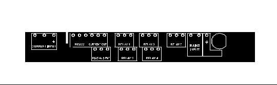
Field wiring connections are made to the back of the panel-mount control unit using the two-part (plug/socket) terminal connectors provided. Figure 3-3 shows the rear panel layout.
Note
The plug/socket terminal connectors on the panel mount unit are polarized (keyed) to prevent inter-changeability and incorrect connection.
Cabling between the Mobrey MCU900 Series control unit and a transmitter should be a screened (shielded), twisted-pair type with the cable screen (shield) connected to terminal 3 (marked with earth/ground symbol) on the control unit. The cable screen (shield) should be left unconnected at the transmitter end unless there is a terminal specifically provided for this purpose. Cable runs should be separate from any high voltage or mains cables to avoid crosstalk or interference.
Connect terminal 30 (intrinsically safe earth/ground) to a high integrity earth/ground point if the transmitter connected to terminals 1 and 2 is sited in a hazardous area.
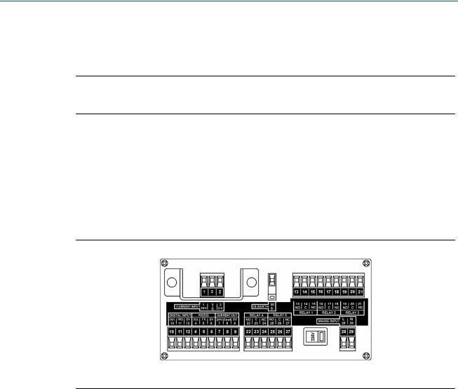
Figure 3-3. Connection terminals layout (for mains-powered panel-mount unit)
(The direct current (dc) powered unit has a slightly different layout – terminals 31 and 32 replace terminals 28 and 29).
Table 3-2. Connection descriptions for panel mount unit
Terminal |
Function |
Terminal marking |
|
|
|
1 |
Loop supply |
24V |
2 |
Current input |
Iin |
3 |
Cable screen Earth |
(Earth symbol) |
4-6 |
RS232 |
RX-TX-0V |
7-9 |
Current output |
24V-Iout-0V |
10-12 |
Digital input 1 and 2 |
IN1-IN2-0V |
13-15 |
Relay 1 |
NO-COM-NC |
16-18 |
Relay 2 |
NO-COM-NC |
19-21 |
Relay 3 |
NO-COM-NC |
22-24 |
Relay 4 |
NO-COM-NC |
25-27 |
Relay 5 |
NO-COM-NC |
28-29 (1) |
Mains input |
L-N |
30 |
I.S. Earth |
(Earth symbol) |
31 (2) |
Negative |
- |
32 (2) |
Positive |
+ |
(1)Mains-powered control unit only.
(2)Direct current (dc) powered control unit only.
Section 3: Installation |
15 |

Section 3: Installation |
Reference Manual |
June 2014 |
IP2030/RM, Rev AA |
3.4.3Power connections
When the control unit is powered by mains alternating current (ac) power, select the voltage as 115V or 230V using the voltage-selector slide switch.
When the control unit is direct current (dc) powered, ensure the supply is adequate (15 to 30 Vdc). Do not exceed 30 Vdc.
A switch or circuit breaker should be installed in close proximity to the instrument, and labelled as such. Although the Mobrey MCU900 Series control unit meets all European standards for surge immunity on power and signal lines, it is recommended that lightning suppressors are also fitted if local conditions make this advisable.
3.4.4Earthing connections
The IP-rated Mobrey MCU900 Series control unit is double insulated and does not require a mains earth.
Do not connect terminal 30 to a mains earth. Terminal 30 is provided for use as an intrinsically safe (or functional) earth connection, which must be used when a transmitter is mounted in a hazardous area and is connected to terminals 1 and 2.
Terminal 3 is to be used for connection of a twisted-pair cable screen (shield) when the control unit is powering the transmitter (see Figure 3-4 on page 17). This screen (shield) should be left unconnected at the transmitter end unless there is a terminal provided for this purpose.
When connected to equipment located in a hazardous area, not meeting the requirements of clause 6.3.12 (Isolation of circuits from earth or frame) in IEC 60079-11:2006
(EN 60079-11:2007), equipotential earthing must be ensured between the equipment and the intrinsically safe earth. An example of equipotential earthing is a cable with a cross-sectional area greater than 4 mm2 and a resistance of less than 1 ohm.
3.4.5Transmitter connections and cabling
Connection of a transmitter to the control unit does not confer intrinsic safety on the transmitter. It is the responsibility of the user to ensure any transmitter installed in a hazardous area is suitable for use and certified accordingly. The installation should be in accordance with a recognized code of practice.
Check that the electrical parameters of the installed system of control unit, transmitter, any loop-powered devices, and interconnecting cable to ensure compliance with the product certificates and technical data. Particular attention must be given to the cable and the transmitter to ensure that the total capacitance and inductance limits stated in the technical data in Appendix B: Product Certifications are not exceeded.
Cable joins are allowable in cabling the transmitter, provided that the joint is made within an IP20/NEMA 3 (minimum) enclosure suitable for the environment, and that wiring withstands a test voltage of 500 V r.m.s. to earth.
The maximum length of cable permissible between the transmitter and control unit is determined by limits imposed by the intrinsic safety certificates of the instruments and control drawings.
16 |
Section 3: Installation |
Reference Manual |
Section 3: Installation |
IP2030/RM, Rev AA |
June 2014 |
No other outputs from the control unit must be routed through a hazardous area unless protected by an additional I.S. Barrier (not supplied).
It is the responsibility of the user to ensure that any transmitter is installed in accordance with the manufacturer’s instructions supplied with the transmitter.
Cable between the MCU900 Series control unit and a transmitter should be shielded twisted-pair with the shield connected to terminal 3 (marked with earth symbol) on the MCU900 Series control unit. The shield should be left unconnected at the transmitter unless there is a terminal specifically provided for this purpose.
Cable runs should be separate from any high voltage or mains cables to avoid crosstalk or interference. Multi-core cable may be used if the other cores carry only low voltage (24 Vdc nominal) signals and each pair of cores is individually screened (shielded).
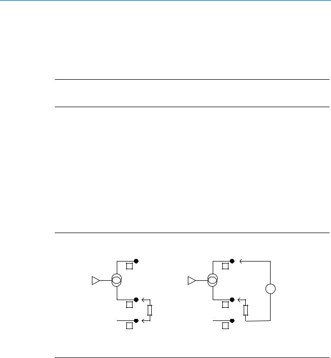
Loop-powered transmitters must be connected to terminals 1, 2, and 3 on the control unit (see Figure 3-4).
The MCU900 Series control unit supplies 23 Vdc from a 400 Ohm source to power transmitters. Separately powered transmitters must be connected to terminals 2 and 3 (see Figure 3-5).
Figure 3-4. Loop-powered transmitter connections to MCU900 Series control unit
A B
24 V |
1 |
|
|
|
|
|
|
|
||||||||
|
IIN |
|
|
|
|
|
|
|
|
|||||||
|
2 |
|
|
|
|
|
|
|
||||||||
|
|
|
|
|
|
|
|
|||||||||
|
|
|
|
|
|
|
|
|
3 |
|
|
|
|
|
|
|
|
|
|
|
|
|
|
|
|
|
|
|
|
|
|
|
|
|
|
|
|
|
|
|
|
|
|
|
|
|
|
|
|
|
|
|
|
|
|
|
|
|
|
|
|
|
|
|
|
|
|
A.Control unit
B.Transmitter
Figure 3-5. Self-powered transmitter connections to MCU900 Series control unit
|
A |
|
24 V |
1 |
B |
|
||
IIN |
2 |
|
|
3 |
|
A.Control unit
B.Transmitter
Section 3: Installation |
17 |
Section 3: Installation |
Reference Manual |
June 2014 |
IP2030/RM, Rev AA |
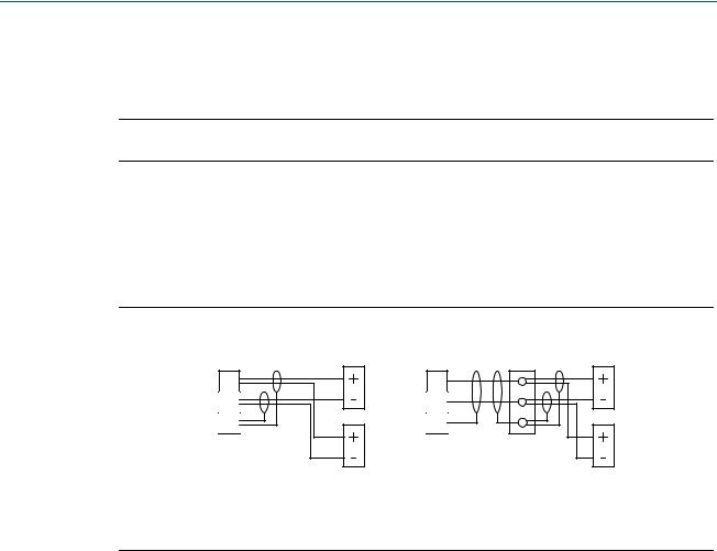
3.4.6Connecting HART transmitters to the Mobrey MCU902
The Mobrey MCU902 control unit takes the input from two HART transmitters and calculates the sum, difference, or product of the two inputs.
Note
The transmitters must be HART compatible for the MCU902 to operate correctly.
Connection of the two transmitters to the MCU902 can be done by:
cabling both transmitter cables wired directly into Current Input terminals on the MCU902 (Figure 3-6), or
using a single cable wired directly into Current Input terminals with the two transmitters connected to this single cable via a suitable junction box (Figure 3-6).
Figure 3-6. Connecting two HART transmitters to the Mobrey MCU902
A |
C |
A |
1 |
1 |
|
2 |
2 |
|
3 |
3 |
|
B B
A.HART Transmitter Tx1
B.HART Transmitter Tx2
C.Junction box
For correct operation, each HART transmitter must be changed to “multi-drop” mode to allow them to communicate with the Mobrey MCU902 control unit through a common connection. Each HART transmitter must therefore have their poll address changed from the factory default address of “0” to a unique address.
The MCU902 control unit is used to achieve this address change, but requires the transmitters to be connected in a specific sequence as detailed here:
1.With the power supply turned off, connect the first HART transmitter to the Current Input terminals on the MCU902 control unit (see Figure 3-6).
2.Check the voltage-selector-switch is set for the correct voltage on the mains-powered control unit (115 or 230 Vac), and then turn the power on.
3.After applying power, the control unit searches for a HART transmitter.
A HART transmitter with the factory default polling address of 0 is found after 15 seconds. The control unit automatically changes the Transmitter Poll Address from “0” to “1” and it is designated “Tx1” (Transmitter 1) and assigned to Channel 1.
The control unit reads parameters from the HART transmitter and makes them available for local interrogation and programming within the menu system.
18 |
Section 3: Installation |

Reference Manual |
Section 3: Installation |
|
IP2030/RM, Rev AA |
June 2014 |
|
|
|
|
4.When an un-configured Mobrey MSP Series Level Transmitter is being used for the first time, a prompt appears asking for the Transmitter [1] Bottom Reference.
If commissioning the system now, edit and save a new Transmitter Bottom Reference or keep the existing Transmitter Bottom Reference. After the start-up process is complete, the display appears showing a measurement e.g. liquid level or the menu system.
If the system is not to be commissioned at this time, simply switch off the power and the same prompt re-appears when switching on the power next time. The Transmitter Bottom Reference can be changed later, but it is better to get it correct now.
Note
If the Re-connecting to Digital Transmitter message does not appear, check that the operating mode of the control unit is set to Run App mode (see page 38) and that the Input Channel Source is set for a digital HART input (see page 48 or page 50)
5.Turn the power supply off and connect the second HART transmitter (see Figure 3-6), such that both HART transmitters are connected at the same time.
6.Turn the power supply on.
7.The MCU902 control unit searches for, and detects, the two connected HART transmitters.
After the second HART transmitter is found, the control unit automatically changes the Transmitter Poll Address from “0” to “2” and it is designated “Tx2” (Transmitter 2) and assigned to Channel 2.
The control unit reads parameters from the HART transmitter and makes them available for local interrogation and programming within the menu system.
8.When an un-configured Mobrey MSP Series Level Transmitter is being used for the first time, a prompt appears asking for the Transmitter [2] Bottom Reference.
If commissioning the system now, edit and save a new Transmitter Bottom Reference or keep the existing Transmitter Bottom Reference. After the start-up process is complete, the display appears showing a measurement e.g. liquid level or the menu system.
If the system is not to be commissioned at this time, simply switch off the power and the same prompt re-appears when switching on the power next time. The Transmitter Bottom Reference can be changed later, but it is better to get it correct now.
9.The two HART transmitters are now known to the control unit, and will be remembered each time the power is switched off and on.
Section 3: Installation |
19 |
Section 3: Installation |
Reference Manual |
June 2014 |
IP2030/RM, Rev AA |
3.4.7Relay connections
The five voltage-free contact relays are grouped as shown in Table 3-3. Whilst each relay is individually double-insulated, their arrangement is such that the insulation between relays in the same group is standard or ‘basic’ insulation. Care must be taken in order to avoid the risk of electric shock. It is allowed to use relays in the same group to control circuits with both mains and dc, or low voltage circuits.
Note
The relay labels (NO-C-NC) in Table 3-1 and Table 3-2 represent the relay terminals in the de-energized state.
Table 3-3. Relay configuration groups
Wall Mount MCU900 Series control unit |
Panel Mount MCU900 Series control unit |
|
|
Relay 1 and 2: Group 1 |
Relay 1, 2 and 3 : Group 1 |
Relay 3 and 4 : Group 2 |
Relay 4 and 5 : Group 2 |
Relay 5: Group 3 |
|
|
|
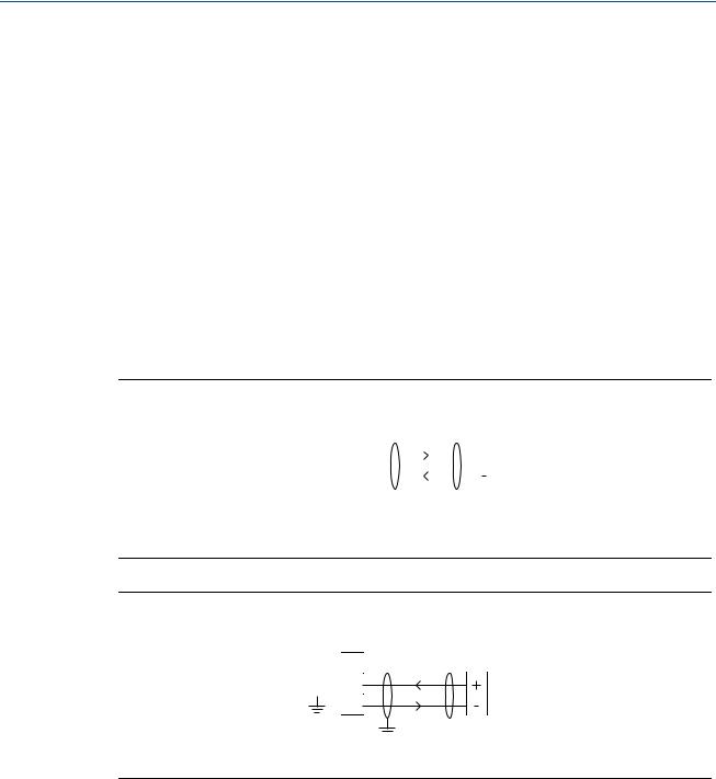
3.4.8Current output connections
The Current Output may be connected in internally-powered or loop-powered mode, as shown in Figure 3-7. In loop-powered mode, an external power source is required. A minimum of 2.5 V dc is required across terminals 7 and 8 for correct operation. The voltage must not exceed 30 Vdc.
Figure 3-7. Alternative output current configurations
24V |
24V |
7 |
7 |
|
|
|
+ |
|
|
|
External |
|
|
|
Supply |
Io |
|
Io |
- |
8 |
+ |
8 |
+ |
|
|
||
|
Load |
|
Load |
0V |
- |
0V |
- |
9 |
|
9 |
|
Internally Powered |
|
Loop Powered |
|
20 |
Section 3: Installation |
Reference Manual |
Section 3: Installation |
IP2030/RM, Rev AA |
June 2014 |
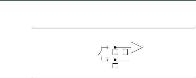
3.4.9Digital control voltage-free contact inputs
There are two trigger inputs, IN1 and IN2. Each input is connected as shown in Figure 3-8.
Figure 3-8. Connections for external trigger input
External |
IN |
|
|
10 |
or 11 |
||
Contact |
|||
0V |
|
||
Closure |
|
||
|
12 |
|
Section 3: Installation |
21 |
Section 3: Installation |
Reference Manual |
June 2014 |
IP2030/RM, Rev AA |
3.4.10RS232 connections
The RS232 connections, terminals 4, 5 and 6, are for downloading logged data to a PC or a handheld device.
Wall-mountable Mobrey MCU90F control units are supplied with a factory pre-fitted RS232 data-download socket, which is also pre-wired to terminals 4, 5, and 6.
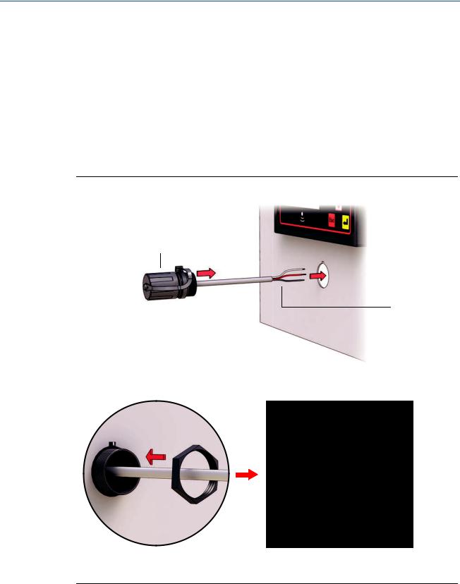
The panel-mountable Mobrey MCU90F control unit is supplied with a data-download socket ready to be fitted to a panel (see Figure 3-9 on page 22) and then wired to terminals 4, 5, and 6 on the rear of the control unit (see Figure 3-10 on page 23).
When there is data to be downloaded using Mobrey LOG-VIEW or other software, connect the RS232 data-download cable supplied with the socket (see Figure 3-11 on page 23).
Figure 3-9. Fitting the RS232 data-download socket to a panel
Cut-out the hole in the panel to the dimensions shown in Figure A-2 on page 122.
Note A
Note B
Use the supplied mini-B nut to secure the socket to the panel.
A.RS232 socket with cap fitted.
B.RS232 socket flying lead.
22 |
Section 3: Installation |
Loading...