


Installation Leaflet
IP227, Rev. AA |
MCU200 |
July 07 |
MCU200 Installation, Operation &
Maintenance Instructions
Contents
1.Sensor installation
2.Control unit installation
3.Applications: 3.1Gain adjustment 3.2Liquid level alarm
3.3Pump control and latching arms 3.4Blanket or interface detection
4.Spare parts and fault finding
WARNING:
If this equipment is used in a manner not specified by the manufacturer, the protection provided may be impaired. All installation and commissioning of this equipment must be carried out by electrically competent persons
Mobrey ultrasonic liquid level control or sludge blanket or interface detection systems using control unit type MCU200
Each Mobrey ultrasonic control system requires a sensor to suit the specific application, plus a control unit.
These installation instructions cover the Mobrey control units in the MCU200 series.
Specification
Power supply |
MCU 201 |
110/120 ±10% |
220/240±10% |
50-60 Hz |
|
Installation category |
MCU 201 |
II-IEC664 for 230V ac supply |
III-IEC664 for 115V ac supply |
||
Pollution degree |
MCU 201 |
2-IEC664 |
|
|
|
Power consumption |
MCU 201 |
6VA approx at 240 Vac |
|
|
|
Power supply |
MCU 203 |
24V dc (20V Min, 30V Max) Supply must be floating or negative earth |
|||
Current consumption |
MCU 203 |
0.1A Max |
|
|
|
Relay output |
|
5A at 230V ac DPCO |
|
|
|
Relay state |
|
Normal state selectable energised/de-energised |
|||
Relay delay |
|
0.5,2,8,30 seconds selectable. Operates for change of relay state in |
|||
|
|
one direction only. 50msecs in other direction. (Approx.) |
|||
LED indicators |
|
Red for alarm, |
Green for normal, |
Yellow for cable fault |
|
LED state |
|
Green/Red indication selectable for either sensor state |
|||
Sensors compatible |
|
Any Mobrey ultrasonic gap, Hisens or Interface sensor |
|||
Sensor frequency |
|
Switch selects electronics operational at either l MHz or 3.7 MHz |
|||
Cable check |
|
Option selectable for certain sensors |
|||
External input |
|
Used to hold relay de-energised to provide pump control |
|||
Box size |
|
200 x 120 x 75mm |
|
|
|
Fixing centres |
|
188 x 188 |
|
|
|
Box rating |
|
IP65 Polycarbonate (clear lid) |
|
|
|
Temperature |
|
-40oC to 55oC ambient |
|
|
|
Holes for glands |
|
3 off 16mmØ |
|
|
|
EMC |
|
Emissions: EN50081-1 |
Immunity: EN50082-1 |
||
Safety |
|
EN61010-1 |
|
|
|
|
|
|
|
|
|
www.mobrey.com

1.Sensor Installation
1.1 General description
Each Mobrey ultrasonic sensor contains two piezoelectric crystals. A high frequency signal (1 MHz or 3.7 MHz) generated by the control unit is transmitted to one piezoelectric crystal by coaxial cable. This crystal converts the electrical signal into an ultrasonic oscillation.
The sensor design allows the ultrasonic oscillation to pass from the transmitter crystal to the receiver piezoelectric crystal. Most Mobrey sensors (300 or 400 series) are “gap” type sensors, where the two piezoelectric crystals are separated by a gap. When the gap is in liquid the signal reaches the receiver, because of the low ultrasonic attenuation of the liquid. When the gap is filled with air, no ultrasonic signal can pass from transmitter to receiver.
See figure 1.
Fig 1.
When the gap is filled with liquid, the piezoelectric receiver crystal converts the ultrasonic wave into an electrical signal, which is transmitted back to the control unit using a second coaxial cable. Usually the two coaxial cables to the sensor are in one overall sheath. The control unit circuitry is a feedback amplifier, which oscillates when the sensor is wet, and is quiescent for the sensor dry. The “oscillating” or “nonoscillating” sensor states dictate the output relay states of the MCU200.
For sludge blanket or interface detection the sensor “oscillates” in a clear liquid, and is “non-oscillating” in the sludge or at the interface. The amplifier gain adjustment determines the sludge density for the change between these two states. See section 3.4.
For Mobrey Hisens sensors, (type numbers HL, HD etc) the metal body of the sensor provides the ultrasonic coupling between the piezoelectric crystals. This coupling is reduced when the sensor is under a liquid, so that for Hisens sensors “oscillating” state is dry, in air, and the “non oscillating” state is wet, submerged in a liquid.
1.2 Switching levels and orientation
Mobrey gap sensors should normally be mounted with the gap vertical, to avoid build up of solids on the sensor faces on either side of the gap. In this condition the switching level will be half way up the face: if the sensor is mounted from the side of the tank this is normally on the centreline of the cylindrical body.
Occasionally such sensors are mounted with the sensor faces horizontal, either to avoid air bubbles passing through the gap or for convenience of installation.
In this case the switching level will be at the sensor face at the top of the gap.
Fig.2. Hi-Sens transducer
The Hi-Sens sensor consists of two ultrasonic transducers mounted on the inside of a cylinder. When the sensor is not submerged in the liquid, the signal from one transducer resonates round the cylinder like a bell ringing. If the liquid rises up around the sensor, this ringing is damped and the signal received by the second transducer is significantly attenuated. The ringing or oscillation of the sensor is detected by the control unit. Switching occurs when the liquid is about half way up the cylinder of the Hi-Sens body.
NOTE: For satisfactory operations the Hi-Sens must not be positioned in a vessel or tube less than 100mm internal diameter.
1.3 Installation of sensor
The sensor must be handled with care - it is a measuring instrument. Before installation, check that sensor, cable and control unit have not been damaged in transit. Drill and tap a hole with a suitable thread. It is advisable to use a boss or similar on thin walls. The sensor has a tapered thread. Use PTFE tape or similar to seal the thread. Mark the sensor hexagon to identify the gap orientation of the sensor, if appropriate. Take care not to damage the sensor cable during tightening.
The cable should be laid on cable trays and separated from any high voltage or mains cables. The normal cable termination is a plastic gland (to fit the MCU200 control box drilled hole) and crimped terminal pins to suit the MCU200 terminals.
1.4 Extension cables
Extension Cables up to 50 metres long can be fitted to most Mobrey ultrasonic sensors in the factory to special order but a better site arrangement is to have a separate extension cable.
When double coaxial cable needs to be extended, two sets of coaxial plugs and sockets will be needed, one set for transmit and one receive.Care must be taken that the connectors are not earthed or shorted together in any way, to prevent crosstalk or pick-up. The coaxial connections must be made in a waterproof junction box. Terminal blocks should not be used. The extension cable needs to be of 50ohm characteristic impedance. Suitable dual coaxial extension cables can be purchased from KDG Mobrey (Part No. K178).
For extensions over 50 metres it is recommended two runs of single coaxial low loss cable is used, with the transmit and return cable runs separated by 0.15 metres to minimise crosstalk.
If several sensor cables are being run together then all the transmit cables (those connected to E2) should be grouped together and all receive cables (those connected to 1E) grouped together maintaining the separation specified above.
2.Control Unit Installation
2.1 Mechanical
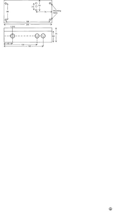
The control unit is supplied with three holes drilled in the bottom (longer) side of the box. Two glands are supplied for the power input cable and relay output cable. The sensor is normally supplied fitted with a suitable gland on the cable. Two further holes can be drilled in the bottom side of the box should these be needed: it is recommended that the circuit board is removed whilst drilling extra gland holes.
Fig. 4 MCU200 housing dimensions
All cable connections are made to the terminal blocks along the bottom edge of the pcb (see fig.5). Release the terminal screw before inserting the wire.
2.2 External Connections
Protection for permanently installed equipment
NOTE: This equipment is regarded as permanently installed equipment and must be wired up using suitable cable for the current and voltage specified. A suitable switch or circuit breaker must be included in the installation and this should be in close proximity to the equipment and marked as its disconnecting device. A suitable fuse rated at 3A must be fitted in the supply. Each relay circuit must be protected by a fuse not exceeding the maximum rated current for the relay as specified in the manual.
Fig 3 Suitable extension cables
50mtr |
50-100m |
over 100m |
RG174 |
URM76 |
Consult |
RG178 |
RG58 |
factory |
|
|
|
Two cables are required per sensor. The RG178 should be used where the cable itself is subject to temperatures exceeding 74°C.
(i)AC Mains is connected between the “N” terminal for neutral and one of the “115V” or “230V” terminals depending on the voltage supply available - BEWARE - the terminal not connected externally will be “live” once the transformer is powered via the other terminals.
(ii)Protective earth
NOTE: A protective earth should be used for all applications
(iii) The DPCO relay has two sets of contacts. These are labelled:
Set 1: |
NC1 |
- Normally closed |
C1 |
- Common |
|
NO1 |
- Normally open |
|
Set 2: |
NC2 |
- Normally closed |
C2 |
- Common |
|
NO2 |
- Normally open |
|
Relay warning
CAUTION: External circuits (such as signal circuits) with accessible parts or basic insulation only, MUST NOT be connected to the relay if the relay is also connected to external circuits which are hazardous live (mains circuits).
(iv)The Sensor connections are labelled “1”, “E” for the receiver crystal and “2”, “E” for the coax cable to the transmitter crystal. The screens of these coax cables are connected to the terminals marked “E”.
(v)The Auxiliary Input is a terminal which can be connected to a “push to reset” button to achieve a latching alarm, or to another Mobrey control unit, to give a pump control from the MCU200 unit relay output. If a short circuit is connected between terminals 3 & 4, the MCU200 relay, once deenergised, is held de-energised. Even if the sensor attached to the MCU200 changes state, to that which should energise the output relay, this relay will not energise until the link between terminals 3 & 4 is broken in the circuit external to the MCU200. See section 3.3.
Fig. 5
MCU201 PC Board
 Loading...