


MRLDS-250
Document Part # 026-4413 Rev 2 Page 1 of 4
©2018 Emerson Climate Technologies Retail Solutions, Inc. This document may be photocopied for personal use.
Visit our website at http://www.emerson.com for the latest technical documentation and updates.
The Modular Refrigeration Leak Detection Sensor is
Emerson’s state-of-the-art infrared refrigerant gas
detector that can detect a wide range of gases. The
MRLDS-250 can be used on a stand-alone basis or
integrated into supervisory controls. The MRLDS-250
can be used in locations that require continuous
monitoring and to add gas detection solutions to an
existing system.
The MRLDS-250 is available in two versions:
• The broadband gas detector is used as a general
purpose gross leak detector and is factory tested and
certified to +/- 35% accuracy.
• The gas specific versions come factory certified and
calibrated with +/- 3% accuracy to the target refrigerant
when there is a need for more accurate detection.
For complete part number and installation information, see
the full MRLDS-250 manual (P/N 026-1315).
MRLDS-250 Installation
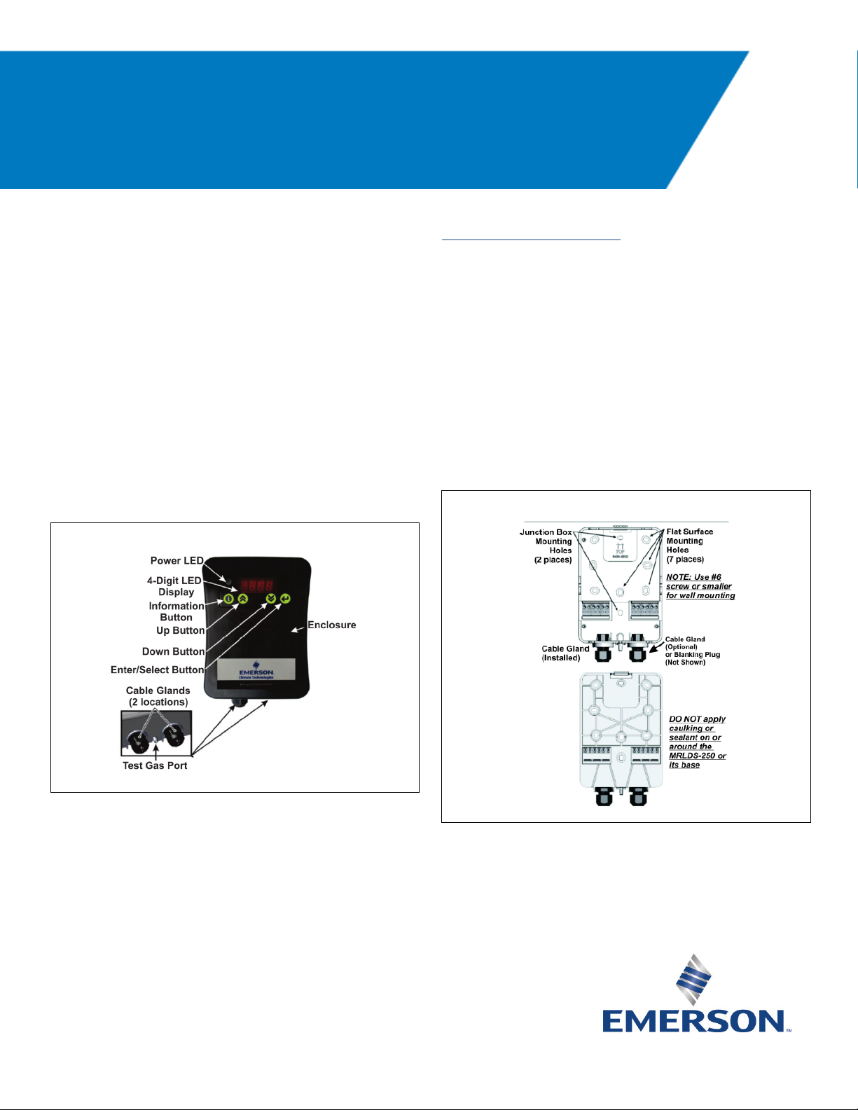
Mounting the MRLDS-250
1. To open the housing as received, use a flat blade
screwdriver and depress the top latch. While pushing
the latch, grasp the back edge of the housing near the
latch and pull the back away.
2. Position the base to the pre-determined mounting
location.
3. For Wall Mount, attach the MRLDS-250 base to the
mounting surface using two #6 screws (provided)
through two of the seven mounting holes
(see Figure 2). For Junction Box Mount, attach the
MRLDS-250 base to the junction box through the two
junction box holes.
Figure 1 - MRLDS-250 Components
Figure 2 - Front and Back of the MRLDS-250 Base
Quick Setup Guide
MRLDS-250
Document Part # 026-4413 Rev 2 Page 2 of 4
©2018 Emerson Climate Technologies Retail Solutions, Inc. This document may be photocopied for personal use.
Visit our website at http://www.emerson.com for the latest technical documentation and updates.
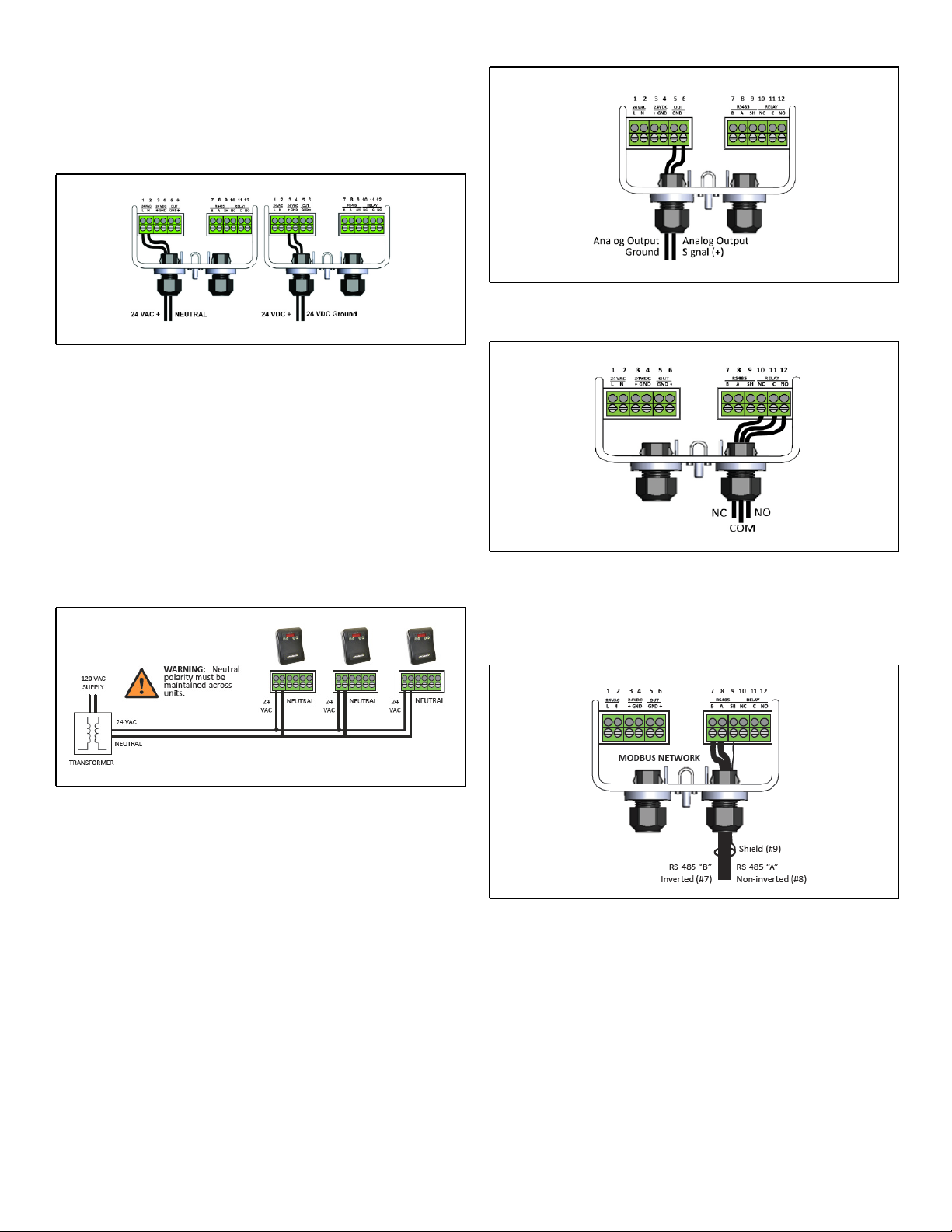
Wiring and Configuration
Either 24VAC or 24VDC may be used to power the
MRLDS-250. Connect wiring to the appropriate terminal
locations. Use two wires, between 14 and 22 AWG.
Refer to Figure 3 for AC wiring (left) or DC wiring (right):
WARNING: The MRLDS-250 must be powered by:
• A suitable UL 60950/CSA certified power supply
that is isolated from line voltage by double
insulation.
• An appropriately rated UL listed/CA Class 2
Transformer; a 10VA Transformer is
recommended.
• For multiple devices cascaded, a 50VA Class 2
Transformer is recommended.
The MRLDS-250 provides an analog output signal that is
proportional to the level of gas detected. Connect two
18 to 20 AWG wires to terminal block positions 5 and 6
(see Figure 5A), noting ground and signal polarity.
Make relay connections (NO, NC, or both) using 18 to 20
AWG wires to terminal block positions 10, 11, and 12
(see Figure 5B), noting normally open, normally closed,
and common connectors.
NOTE: For MODBUS network communications wiring,
use only 18-24 AWG shielded twisted pair wire with 120
ohm characteristic impedance.
Figure 3 - Supply and Power Wiring Options
Figure 4 - Power Wiring of a Device Network
Figure 5A - Analog Output Wiring
Figure 5B - Sample Relay Output Wiring
Figure 6 - MODBUS Network Communication Wiring
 Loading...