


Liebert DS 28-105kW
Table of contents
 Loading...
Precision Cooling
For Business-Critical Continuity™
Liebert
®
Air Economizer
™
for Liebert DS
™
, Liebert CW
™
& Liebert Challenger
™
3000
User Manual
GENERAL SAFETY GUIDELINES
Before beginning the installation of the Liebert Air Economizer, read all instructions, verify that all the parts
are included, and check the nameplate to be sure the Liebert Air Economizer voltage matches available util-
ity power.
Follow all local and national codes.
!
WARNING
Risk of electric shock. Can cause injury or death.
Disconnect all local and remote electric power supplies before working within.
!
WARNING
Risk of unit falling over. Can cause death, injury and equipment damage.
The Liebert Air Economizer is top-heavy. Use extreme caution and care when moving and
installing this unit.
!
CAUTION
Risk of piping and component rupture. May cause injury or equipment damage.
Closing service valves may isolate liquid refrigerant, causing high pressure and rupture of
piping. Do not close valves without following recommended procedures for repair,
maintenance and replacement of components. Install pressure relief valves in field piping
that may become isolated by service valves.
NOTE
This document is to be used together with site-specific documentation and documentation for
other parts of the system (heat rejection devices and cooling modules).
NOTE
Before any action that could cause a disturbance in the cooling system’s function is begun, the
facility manager MUST be informed. In addition, after the action is taken and the work is
finished, the facility manager MUST be informed.

i
TABLE OF CONTENTS
GENERAL SAFETY GUIDELINES . . . . . . . . . . . . . . . . . . . . . . . . . . . . . . . . . . . INSIDE FRONT COVER
1.0 PRODUCT DESCRIPTION . . . . . . . . . . . . . . . . . . . . . . . . . . . . . . . . . . . . . . . . . . . . . . . . . . .1
1.1 General Product Information. . . . . . . . . . . . . . . . . . . . . . . . . . . . . . . . . . . . . . . . . . . . . . . . . . . 1
1.1.1 Customer-Supplied Equipment and Ductwork . . . . . . . . . . . . . . . . . . . . . . . . . . . . . . . . . . . . . . 1
1.2 Equipment Inspection . . . . . . . . . . . . . . . . . . . . . . . . . . . . . . . . . . . . . . . . . . . . . . . . . . . . . . . . 2
1.3 Equipment Handling . . . . . . . . . . . . . . . . . . . . . . . . . . . . . . . . . . . . . . . . . . . . . . . . . . . . . . . . . 2
1.3.1 Handle the Liebert Air Economizer With Skid. . . . . . . . . . . . . . . . . . . . . . . . . . . . . . . . . . . . . . 3
1.3.2 Move the Liebert Air Economizer With a Forklift . . . . . . . . . . . . . . . . . . . . . . . . . . . . . . . . . . . 3
1.4 Unpack the Liebert Air Economizer . . . . . . . . . . . . . . . . . . . . . . . . . . . . . . . . . . . . . . . . . . . . . 3
2.0 INSTALLATION . . . . . . . . . . . . . . . . . . . . . . . . . . . . . . . . . . . . . . . . . . . . . . . . . . . . . . . . . .4
2.1 General Considerations . . . . . . . . . . . . . . . . . . . . . . . . . . . . . . . . . . . . . . . . . . . . . . . . . . . . . . . 4
2.2 Install the Liebert Air Economizer—Preliminary Steps . . . . . . . . . . . . . . . . . . . . . . . . . . . . . 4
2.2.1 Position the Liebert Air Economizer on a Liebert CW . . . . . . . . . . . . . . . . . . . . . . . . . . . . . . . . 4
2.2.2 Position the Liebert Air Economizer on a Liebert DS . . . . . . . . . . . . . . . . . . . . . . . . . . . . . . . . 5
2.3 Wiring the Liebert Air Economizer . . . . . . . . . . . . . . . . . . . . . . . . . . . . . . . . . . . . . . . . . . . . . . 9
2.3.1 Wire the Dampers. . . . . . . . . . . . . . . . . . . . . . . . . . . . . . . . . . . . . . . . . . . . . . . . . . . . . . . . . . . . 10
2.3.2 Outdoor Air and Return Air Temperature and Humidity Sensor Connections . . . . . . . . . . . 11
2.4 Adjust the Restricted Airflow Switch . . . . . . . . . . . . . . . . . . . . . . . . . . . . . . . . . . . . . . . . . . . 12
3.0 INSTALLATION CHECKLIST . . . . . . . . . . . . . . . . . . . . . . . . . . . . . . . . . . . . . . . . . . . . . . . .13
4.0 OPERATION . . . . . . . . . . . . . . . . . . . . . . . . . . . . . . . . . . . . . . . . . . . . . . . . . . . . . . . . . . .14
4.1 Operational Condition . . . . . . . . . . . . . . . . . . . . . . . . . . . . . . . . . . . . . . . . . . . . . . . . . . . . . . . 15
4.1.1 Normal Operation. . . . . . . . . . . . . . . . . . . . . . . . . . . . . . . . . . . . . . . . . . . . . . . . . . . . . . . . . . . . 15
4.2 System Overview . . . . . . . . . . . . . . . . . . . . . . . . . . . . . . . . . . . . . . . . . . . . . . . . . . . . . . . . . . . 15
4.2.1 Out of Service . . . . . . . . . . . . . . . . . . . . . . . . . . . . . . . . . . . . . . . . . . . . . . . . . . . . . . . . . . . . . . . 17
4.2.2 Fan Speed Control . . . . . . . . . . . . . . . . . . . . . . . . . . . . . . . . . . . . . . . . . . . . . . . . . . . . . . . . . . . 22
4.2.3 Variable Speed Fan Operation (VFD and EC Fan) . . . . . . . . . . . . . . . . . . . . . . . . . . . . . . . . . 22
4.2.4 Disable the Liebert Air Economizer . . . . . . . . . . . . . . . . . . . . . . . . . . . . . . . . . . . . . . . . . . . . . 22
4.3 Control Menu Settings . . . . . . . . . . . . . . . . . . . . . . . . . . . . . . . . . . . . . . . . . . . . . . . . . . . . . . . 22
4.3.1 Liebert Air Economizer Status Screen . . . . . . . . . . . . . . . . . . . . . . . . . . . . . . . . . . . . . . . . . . . 23
4.4 Temperature Control Modes—P and PI . . . . . . . . . . . . . . . . . . . . . . . . . . . . . . . . . . . . . . . . . 23
4.4.1 Proportional Control. . . . . . . . . . . . . . . . . . . . . . . . . . . . . . . . . . . . . . . . . . . . . . . . . . . . . . . . . . 23
4.4.2 Proportional Integral Control . . . . . . . . . . . . . . . . . . . . . . . . . . . . . . . . . . . . . . . . . . . . . . . . . . 23
4.4.3 Integral Wind-up . . . . . . . . . . . . . . . . . . . . . . . . . . . . . . . . . . . . . . . . . . . . . . . . . . . . . . . . . . . . 23
4.4.4 Controller Tuning . . . . . . . . . . . . . . . . . . . . . . . . . . . . . . . . . . . . . . . . . . . . . . . . . . . . . . . . . . . . 24
5.0 MAINTENANCE . . . . . . . . . . . . . . . . . . . . . . . . . . . . . . . . . . . . . . . . . . . . . . . . . . . . . . . . .26
6.0 TROUBLESHOOTING . . . . . . . . . . . . . . . . . . . . . . . . . . . . . . . . . . . . . . . . . . . . . . . . . . . . .27

ii
FIGURES
Figure 1 Liebert Air Economizer arrangement, typical. . . . . . . . . . . . . . . . . . . . . . . . . . . . . . . . . . . . . . . . . . 2
Figure 2 Dimensions—Liebert Air Economizer and Liebert CW models CW106D/114D . . . . . . . . . . . . . . . 6
Figure 3 Dimensions—Liebert Air Economizer and Liebert CW models CW026D-CW084D . . . . . . . . . . . . 7
Figure 4 Dimensions—Liebert Air Economizer and Liebert DS downflow units, 28-105kW (8-30 tons) . . . 8
Figure 5 Damper wiring connections—Liebert DS and Liebert CW units . . . . . . . . . . . . . . . . . . . . . . . . . . 10
Figure 6 Temperature and humidity sensor connections—Liebert DS and Liebert CW . . . . . . . . . . . . . . . 11
Figure 7 Supply limit thermistor wiring and restricted airflow switch location . . . . . . . . . . . . . . . . . . . . . 12
Figure 8 Operational ranges for chilled water systems and for compressor/chilled water systems . . . . . . 15
Figure 9 Air flow pattern of a Liebert Air Economizer system . . . . . . . . . . . . . . . . . . . . . . . . . . . . . . . . . . . 16
Figure 10 Liebert DS setpoints screen, page 4 of 6 . . . . . . . . . . . . . . . . . . . . . . . . . . . . . . . . . . . . . . . . . . . . . 18
Figure 11 Service/Economizer, page 1 of 3 . . . . . . . . . . . . . . . . . . . . . . . . . . . . . . . . . . . . . . . . . . . . . . . . . . . . 19
Figure 12 Outdoor sensor data screen . . . . . . . . . . . . . . . . . . . . . . . . . . . . . . . . . . . . . . . . . . . . . . . . . . . . . . . 20
Figure 13 Damper settings and limits screen . . . . . . . . . . . . . . . . . . . . . . . . . . . . . . . . . . . . . . . . . . . . . . . . . 21
Figure 14 Deactivation switch. . . . . . . . . . . . . . . . . . . . . . . . . . . . . . . . . . . . . . . . . . . . . . . . . . . . . . . . . . . . . . 22
Figure 15 Liebert iCOM Wellness menu, page 9 . . . . . . . . . . . . . . . . . . . . . . . . . . . . . . . . . . . . . . . . . . . . . . . 25
TABLES
Table 1 Dimensions—Liebert Air Economizer and Liebert CW models CW026D-CW084D . . . . . . . . . . . . 7
Table 2 Liebert DS model dimensional data, 28-105kW (8-30 tons) . . . . . . . . . . . . . . . . . . . . . . . . . . . . . . . 8
Table 3 Liebert Air Economizer troubleshooting . . . . . . . . . . . . . . . . . . . . . . . . . . . . . . . . . . . . . . . . . . . . . 27

Product Description
1
1.0 PRODUCT DESCRIPTION
1.1 General Product Information
The Liebert Air Economizer is an option for Liebert DS downflow units, Liebert CW chilled water
downflow and Liebert Challenger 3000 downflow units. The Liebert Air Economizer uses cool outdoor
air in mild climates to condition indoor spaces. It is functional only on cooling units with Liebert
iCOM
®
controls that have been factory-wired and configured to accommodate the Liebert Air
Economizer.
The Liebert Air Economizer is supplied with electrical wiring for connection to the cooling unit,
outdoor air sensors, return air sensors and a temperature-and-humidity-sensing unit.
Special firmware is loaded into the primary cooling unit at the factory to permit the primary cooling
unit to control the Liebert Air Economizer.
1.1.1 Customer-Supplied Equipment and Ductwork
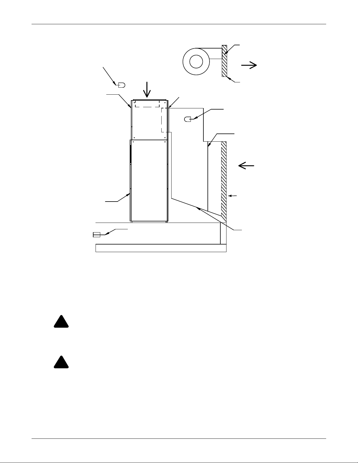
Installation and operation requires outside-air entry ductwork with louvers, screening and filtration
to prevent intrusion of precipitation, particulates, vermin and unauthorized entry (see Figure 1).
Proper installation also requires a customer-provided powered relief-air discharge to rid the structure
of the outside air drawn in for cooling. The relief-air discharge must be equivalent to the airflow of the
total of all cooling systems equipped with the Liebert Air Economizer.
A flange is provided to attach the Liebert Air Economizer to the outdoor air duct Figures 2, 3 and 4.
NOTE
When upgrading the firmware for the primary cooling unit, either a Liebert DS downflow unit
or Liebert CW downflow unit, ensure that the new firmware includes the Liebert Air
Economizer controls. If in doubt, contact the factory.
Product Description
2
Figure 1 Liebert Air Economizer arrangement, typical
1.2 Equipment Inspection
When the unit is delivered, inspect all items for visible and concealed damage. Report any damage to
the carrier immediately and a file a damage claim. Send a copy of the damage claim to Emerson
Network Power or to your sales representative.
1.3 Equipment Handling
!
WARNING
Risk of top-heavy unit falling over. Improper handling can cause equipment damage, injury or
death.
Read all of the following instructions before attempting to move, lift, remove packaging from
or preparing unit for installation.
!
WARNING
Risk of sharp edges, splinters and exposed fasteners. Can cause personal injury.
Only properly trained and qualified personnel wearing appropriate safety headgear, gloves,
shoes and glasses should attempt to move, lift, remove packaging from or prepare this unit for
installation.
DPN001333
Rev. 0
Outside Air Duct
(by others)
Outside Opening with
Louvers, Screen and Bars
to prevent precipitation,
vermin and human entry
(by others)
Liebert
Unit
(Front)
Plenum
Room
Return
Air
Outside
Air Entry
Size collar according
to cooling unit opening
Return Air Sensors
(Field-installed
above damper)
Supply Air Limit Thermistor
(Field-installed under floor)
Outdoor Air Sensor
(Field-installed inside duct;
labeled “Outdoor” Sensor)
Filter
(by others)
Powered Outdoor
Relief Opening
(by others)
Room Relief Air
Discharge (sized and
provided by others)
Relief Air

Product Description
3
1.3.1 Handle the Liebert Air Economizer With Skid
• Always keep the unit upright, indoors and protected from damage.
• If possible, transport the unit using a pallet jack or forklift.
• Personnel should be properly certified and trained to move and rig equipment.
• If using a forklift, make sure that the forks (if adjustable) are spread to the widest allowable dis-
tance that will fit under the skid.
• When moving the skidded Liebert Air Economizer with a forklift, do not lift the unit any higher
than 6" (152mm). If circumstances require the unit to be lifted higher than 6" (152mm), all per-
sonnel not directly involved in raising the unit must be no closer than 20 feet (5m) from the lift
point of the unit.
1.3.2 Move the Liebert Air Economizer With a Forklift
1. Remove the exterior packaging.
2. Align forklift with either the front or rear of the unit. Ensure that the forks are locked at the
widest position that will fit under pallet.
3. Drive the forklift forward, sliding the forks under the base of the unit.
4. Move the Liebert Air Economizer as close to its installation location as possible.
NOTICE
Verify that the floor will support the cooling unit and the Liebert Air Economizer. If a forklift
will be used to move either unit, verify that the floor will support the forklift.
1.4 Unpack the Liebert Air Economizer
Save all recyclable materials for reuse. Dispose of any non-recyclable materials properly.
1. Cut the bands securing the Liebert Air Economizer to its skid.
2. Remove any protective and cushioning material.
3. Remove the plastic bag from the unit.
!
WARNING
Risk of sharp bands under tension. Can cause personal injury.
The bands securing the Liebert Air Economizer to the skid are under extreme tension. Only
properly trained and qualified personnel wearing appropriate safety headgear, gloves, shoes
and glasses should attempt to remove packaging from this unit.

Installation
4
2.0 INSTALLATION
Install the Liebert Air Economizer in accordance with the instructions in this manual and site specific
documentation.
2.1 General Considerations
Emerson Network Power recommends installing the cooling unit to be equipped with the Liebert Air
Economizer, then installing the Liebert Air Economizer and then installing the ductwork.
The ductwork to the outside must be constructed to mate with the outside air intake on the rear of the
Liebert Air Economizer. For dimensions and specifications, see Figures 2, 3 and 4 and Tables 1
and 2.
2.2 Install the Liebert Air Economizer—Preliminary Steps
1. Remove the exterior panels from the Liebert Air Economizer to lighten it and to gain access to the
unit’s frame.
2. Attach the safety straps, slings or belts to the Liebert Air Economizer’s frame.
3. Attach the lifting method or mechanism to the Liebert Air Economizer.
4. Raise the Liebert Air Economizer and position it on the cooling unit and connect the units as
described in either 2.2.1 - Position the Liebert Air Economizer on a Liebert CW or 2.2.2 -
Position the Liebert Air Economizer on a Liebert DS.
2.2.1 Position the Liebert Air Economizer on a Liebert CW
The Liebert CW has flanges to help position and attach the Liebert Air Economizer.
1. Fit the Liebert Air Economizer over the flanges on either end of the Liebert CW.
2. Fit the Liebert Air Economizer inside the flange on the rear of the cooling unit.
Secure the Liebert Air Economizer to the Liebert CW
The Liebert Air Economizer must be attached to the cooling unit to prevent movement. Use field-
supplied, sheet metal screws with blunt tips to connect the units on each end.
NOTICE
Do not drill or screw into the rear of either the Liebert Air Economizer or the Liebert CW.
Screws should be used on both ends of the units.
1. Working from inside, drill two holes in the flange on each end of the Liebert CW and into the
frame of the Liebert Air Economizer.
2. Insert the sheet metal screws into the frame of the Liebert Air Economizer and tighten until the
units are securely attached.
3. After the units are securely connected, remove the safety straps attached in Step 2 in 2.2 -
Install the Liebert Air Economizer—Preliminary Steps.
4. Clean up any metal particles and other debris from the installation.
5. Reattach the exterior panels to the Liebert Air Economizer.
!
WARNING
Risk of heavy unit falling. Can cause equipment damage, personal injury and death.
The Liebert Air Economizer is heavy. The heaviest unit weighs more than 480lb. (218kg)
without its exterior panels. Verify that all lifting and supporting mechanisms and methods
are adequate for the weight of the Liebert Air Economizer being installed. See the
documentation included with the unit.
When raising the Liebert Air Economizer, secure it to sufficiently strong overhead structure
with straps, slings and or belts for safety to prevent it from falling. Spreader bars may be
required with some lifting or securing methods to prevent damaging the Liebert Air
Economizer.

Installation
5
2.2.2 Position the Liebert Air Economizer on a Liebert DS
The Liebert DS has no flanges on top. Position the Liebert Air Economizer on top of the Liebert DS so
that it covers the air entry opening and the plenum and unit will be flush on the ends and back when
the panels are installed.
1. Locate the holes in the rear filter support flange in the plenum; use these as guides to drill screw
pilot holes into the top of the unit rear sheet metal blocker.
2. Insert sheet metal screws through these flanges into the top of the unit.
3. Measure and mark the distance from the front of the electric box top flange in unit back to the
center of the plenum frame bottom 1 x 1 tubing, approximately 1-1/2" (38mm).
4. Cover electric box components to prevent metal shavings and debris contamination from the
drilling process.
5. Drill screw pilot holes from inside the electric box up through the plenum frame (3-6 places
depending on length of plenum).
6. Insert screws through electric box and plenum tubing to secure the front of the plenum.
7. After the units are securely connected, remove the safety straps attached in Step 2 in 2.2 -
Install the Liebert Air Economizer—Preliminary Steps.
8. Clean up any metal particles and other debris from the installation.
9. Reattach the exterior panels to the Liebert Air Economizer.
!
WARNING
Risk of heavy unit falling. Can cause equipment damage, personal injury or death.
The Liebert Air Economizer must be supported until it is securely connected to the Liebert DS
to prevent it from slipping off the cooling unit.
Installation
6
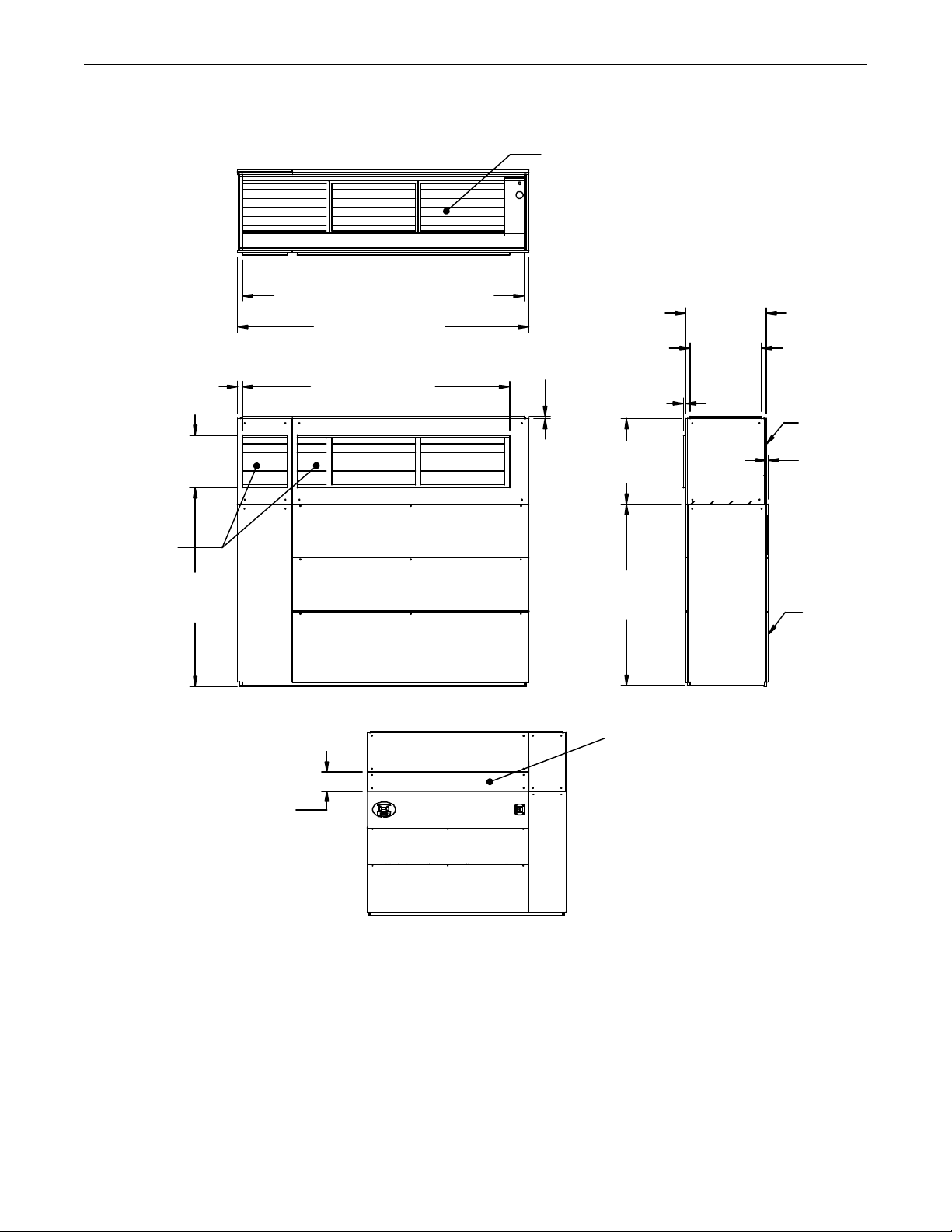
Figure 2 Dimensions—Liebert Air Economizer and Liebert CW models CW106D/114D
122" (3099mm)
BACK VIEW
SIDE VIEW
TOP VIEW
Plenum
Liebert
CW
DPN001332
Rev. 0
Room Return
Air Damper
FRONT VIEW
(Reference only)
Access Panel
for 2" Pre-Filters
Outside Air
Damper
118" 2996mm Duct Flange
1" (25mm)
Duct Collar
76"
(1930mm)
36"
(914mm)
34"
(864mm)
1" (25mm)
1"
(25mm)
22"
(559mm)
12"
(305mm)
30-1/16"
(764mm)
112" (2845mm)
2" (51mm)
83"
(2108mm)
Typical unit shown.
Refer to dimensions and layout for your unit.
Loading...