


 Loading...


 Precision Cooling


 For Business-Critical Continuity™


 Liebert® CRV™


 User Manual–60Hz, 24-Inch Wide, Air-Cooled, Water/Glycol-Cooled and Chilled Water

MODEL NUMBER NOMENCLATURE - 25 DIGIT CONFIGURATION NUMBER
|
|
Model # Part 1 * |
|
|
|
|
|
|
|
Model Details |
|
|
|
|
Model # Part 2 * |
|||||||||
|
|
|
|
|
|
|
|
|
|
|
|
|
|
|
|
|
|
|
|
|
|
|
|
|
1 |
2 |
3 |
4 |
5 |
6 |
7 |
8 |
9 |
10 |
11 |
12 |
13 |
14 |
15 |
16 |
17 |
18 |
19 |
20 |
21 |
22 |
23 |
24 |
25 |
C R 0 2 0 R A 1 C 7 |
S D |
1 |
8 |
1 |
1 |
E |
L |
1 |
0 |
P |
A |
* |
* |
* |
||||||||||
|
|
|
|
|
|
|
|
|
|
|
|
|
|
|||||||||||
Digits 1-2 - Unit Family |
|
|
|
|
|
|
|
Digit 17 - High-Voltage Options |
|
|
|
|
|
|||||||||||
Liebert® CRV™ = CR |
|
|
|
|
|
|
|
|
L or A = NO dual-float condensate pump (for units without |
|||||||||||||||
Digits 3-5 - Nominal Capacity, kW |
|
|
|
|
|
humidifier), 5kA SCCR** |
|
|
|
|
|
|
||||||||||||
DX = 020, 035 |
|
|
|
|
|
|
|
|
|
5 or E = Dual-float condensate pump (for units with or |
|
|||||||||||||
CW = 040 |
|
|
|
|
|
|
|
|
|
|
|
without humidifier), 5kA SCCR** |
|
|
|
|
||||||||
Digit 6 |
|
|
|
|
|
|
|
|
|
|
|
M = No dual-float condensate pump (for units without |
|
|||||||||||
R = Row-Based, 1100mm unit depth |
|
|
|
|
humidifier), 65kA SCCR, 600 series only |
|
|
|
||||||||||||||||
Digit 7 - System Type |
|
|
|
|
|
|
|
|
P = Dual-float condensate Pump (for units with or without |
|||||||||||||||
A = Air Cooled |
|
|
|
|
|
|
|
|
|
humidifier), 65kA SCCR, 600 series only |
|
|
|
|||||||||||
W = Water\Glycol Cooled |
|
|
|
|
|
|
Digit 18 - Option Package |
|
|
|
|
|
|
|||||||||||
C = Chilled Water Cooled |
|
|
|
|
|
|
|
0 = None |
|
|
|
|
|
|
|
|
|
|||||||
Digit 8 - Fan Type |
|
|
|
|
|
|
|
|
|
H = Reheat and Humidifier Lockout |
|
|
|
|
||||||||||
Variable Speed EC Plug Fans = 1 |
|
|
|
|
|
C = Reheat and Humidifier Lockout Additional Alarm |
|
|||||||||||||||||
Digit 9 - Power Supply |
|
|
|
|
|
|
|
|
Contact |
|
|
|
|
|
|
|
|
|
||||||
A = 460V / 3ph / 60Hz |
|
|
|
|
|
|
|
|
D = Low Sound Package (20kW and 35kW only) |
|
|
|||||||||||||
C = 208V / 3ph / 60Hz |
|
|
|
|
|
|
|
|
L = Low Sound Package & Reheat and Humidifier Lockout |
|||||||||||||||
Digit 10 - Cooling System |
|
|
|
|
|
|
|
and Additional Alarm Contact (20kW and 35kW only) |
|
|||||||||||||||
2 |
= Two-Way Valve (CW Only) |
|
|
|
|
|
Digit 19 - Liebert IntelliSlot® Housing |
|
|
|
|
|||||||||||||
3 |
= Three-Way Valve (CW Only) |
|
|
|
|
|
0 = No Cards |
|
|
|
|
|
|
|
|
|||||||||
7 |
= R-410A Digital Scroll Single Circuit (DX Only) |
|
|
1 = (1) Web Card |
|
|
|
|
|
|
|
|
||||||||||||
Digit 11 - Humidifier |
|
|
|
|
|
|
|
|
2 = (2) Web Cards |
|
|
|
|
|
|
|
||||||||
0 |
= None |
|
|
|
|
|
|
|
|
|
|
|
3 = (1) 485 Card |
|
|
|
|
|
|
|
|
|||
S = Steam Generating Canister |
|
|
|
|
|
|
4 = (2) 485 Cards |
|
|
|
|
|
|
|
|
|||||||||
Digit 12 - Display Type |
|
|
|
|
|
|
|
|
5 = (1) Web Card and (1) 485 Card |
|
|
|
|
|||||||||||
D = Liebert iCOM Control with Large Graphic Display |
|
C = (1) Liebert SiteLink-E Card |
|
|
|
|
|
|||||||||||||||||
Digit 13 - Reheat |
|
|
|
|
|
|
|
|
|
D = (1) Liebert SiteLink-E Card and (1) Web Card |
|
|
||||||||||||
0 |
= None |
|
|
|
|
|
|
|
|
|
|
|
E = (1) Liebert SiteLink-E Card and (1) IS-485 Card |
|
||||||||||
1 |
= Electric Reheat |
|
|
|
|
|
|
|
|
F = (1) Building Management Card |
|
|
|
|
|
|||||||||
Digit 14 - Air Filter |
|
|
|
|
|
|
|
|
|
G = (2) Building Management Cards |
|
|
|
|
||||||||||
8 |
= 4" MERV 8 + Clogged Filter Alarm |
|
|
|
|
H = (1) Building Management Card and (1) Web Card |
|
|||||||||||||||||
9 |
= 4" MERV 11 + Clogged Filter Alarm |
|
|
|
|
J = (1) Building Management Card and (1) IS-485 Card |
|
|||||||||||||||||
Digit 15 - Water/Glycol Valve Type |
|
|
|
|
|
K = (1) Building Management Card and (1) Liebert |
|
|
||||||||||||||||
1 |
= Two-Way Valve (W/G only) OR |
|
|
|
|
|
SiteLink-E Card |
|
|
|
|
|
|
|
||||||||||
|
|
Default Air-Cooled Selection |
|
|
|
|
Digit 20 - Future Options |
|
|
|
|
|
|
|||||||||||
7 |
= Three-Way Valve (W/G only) |
|
|
|
|
|
0 = None |
|
|
|
|
|
|
|
|
|
||||||||
H = Default CW Selection |
|
|
|
|
|
|
Digit 21 - Packaging |
|
|
|
|
|
|
|
||||||||||
Digit 16 - Unit Color |
|
|
|
|
|
|
|
|
P = Domestic |
|
|
|
|
|
|
|
|
|||||||
1 |
= Standard Color (Z-7021 Black) |
|
|
|
|
|
S = Export (Seaworthy) |
|
|
|
|
|
|
|
||||||||||
2 |
= Non-Standard Color |
|
|
|
|
|
|
Digit 22 - Special Features |
|
|
|
|
|
|
||||||||||
|
|
|
|
|
|
|
|
|
|
|
|
|
|
A = No SFAs, Standard Unit |
|
|
|
|
|
|
||||
X = SFA Included
Digits 23-25 - Factory Configuration Number
*The 14-digit model number consists of the first 10 digits and last four digits of the Configuration Number.
**L and 5 for CW models; A and E for DX models.

TABLE OF CONTENTS
1.0 LIEBERT CRV COMPONENT LOCATION . . . . . . . . . . . . . . . . . . . . . . . . . . . . . . . . . . . . . . . .4 2.0 INTRODUCTION . . . . . . . . . . . . . . . . . . . . . . . . . . . . . . . . . . . . . . . . . . . . . . . . . . . . . . . . . .7
2.1 Product Description . . . . . . . . . . . . . . . . . . . . . . . . . . . . . . . . . . . . . . . . . . . . . . . . . . . . . . . . . . 7
3.0 INSPECTION AND UNPACKING . . . . . . . . . . . . . . . . . . . . . . . . . . . . . . . . . . . . . . . . . . . . . . .8
3.1 Equipment Inspection . . . . . . . . . . . . . . . . . . . . . . . . . . . . . . . . . . . . . . . . . . . . . . . . . . . . . . . . 8
3.1.1 Packing Material . . . . . . . . . . . . . . . . . . . . . . . . . . . . . . . . . . . . . . . . . . . . . . . . . . . . . . . . . . . . . 8
3.2 Handling . . . . . . . . . . . . . . . . . . . . . . . . . . . . . . . . . . . . . . . . . . . . . . . . . . . . . . . . . . . . . . . . . . . 8
3.2.1 Handling the Unit While it is Packaged . . . . . . . . . . . . . . . . . . . . . . . . . . . . . . . . . . . . . . . . . . . 9
3.3 Moving the Unit Using Rigging. . . . . . . . . . . . . . . . . . . . . . . . . . . . . . . . . . . . . . . . . . . . . . . . 10 3.4 Unpacking the Liebert CRV. . . . . . . . . . . . . . . . . . . . . . . . . . . . . . . . . . . . . . . . . . . . . . . . . . . 10 3.5 Removing the Unit from the Skid . . . . . . . . . . . . . . . . . . . . . . . . . . . . . . . . . . . . . . . . . . . . . . 11 3.6 Reattach the Baffle Panel . . . . . . . . . . . . . . . . . . . . . . . . . . . . . . . . . . . . . . . . . . . . . . . . . . . . 12
4.0 PREPARE THE LIEBERT CRV FOR INSTALLATION . . . . . . . . . . . . . . . . . . . . . . . . . . . . . . . .13 5.0 PIPING . . . . . . . . . . . . . . . . . . . . . . . . . . . . . . . . . . . . . . . . . . . . . . . . . . . . . . . . . . . . . . .14
5.1 Fluid Connections. . . . . . . . . . . . . . . . . . . . . . . . . . . . . . . . . . . . . . . . . . . . . . . . . . . . . . . . . . . 14
5.1.1 Condensate Piping—Field-Installed . . . . . . . . . . . . . . . . . . . . . . . . . . . . . . . . . . . . . . . . . . . . . 15 5.1.2 Humidifier Supply Water—Optional Steam Generating Canister . . . . . . . . . . . . . . . . . . . . . 15 5.1.3 Requirements of Systems Using Water or Glycol. . . . . . . . . . . . . . . . . . . . . . . . . . . . . . . . . . . 16
6.0 REFRIGERANT CONNECTIONS . . . . . . . . . . . . . . . . . . . . . . . . . . . . . . . . . . . . . . . . . . . . . .18
6.1 Piping Guidelines—Air-Cooled Units . . . . . . . . . . . . . . . . . . . . . . . . . . . . . . . . . . . . . . . . . . . 19 6.2 Refrigerant Piping—Air-Cooled Models . . . . . . . . . . . . . . . . . . . . . . . . . . . . . . . . . . . . . . . . . 19
6.2.1 General Layout . . . . . . . . . . . . . . . . . . . . . . . . . . . . . . . . . . . . . . . . . . . . . . . . . . . . . . . . . . . . . . 20 6.2.2 Pipe Diameter and Thickness . . . . . . . . . . . . . . . . . . . . . . . . . . . . . . . . . . . . . . . . . . . . . . . . . . 21 6.2.3 Installing Piping . . . . . . . . . . . . . . . . . . . . . . . . . . . . . . . . . . . . . . . . . . . . . . . . . . . . . . . . . . . . . 23
6.3 Vacuum and Refrigerant Charge. . . . . . . . . . . . . . . . . . . . . . . . . . . . . . . . . . . . . . . . . . . . . . . 26
6.3.1 Evacuation Air-Cooled Models. . . . . . . . . . . . . . . . . . . . . . . . . . . . . . . . . . . . . . . . . . . . . . . . . . 27
7.0 WATER CONNECTIONS . . . . . . . . . . . . . . . . . . . . . . . . . . . . . . . . . . . . . . . . . . . . . . . . . . .29
7.1 Water Connections—Supply Humidifier and Drain Water, All Models . . . . . . . . . . . . . . . . 29 7.2 Glycol Mixture . . . . . . . . . . . . . . . . . . . . . . . . . . . . . . . . . . . . . . . . . . . . . . . . . . . . . . . . . . . . . 30 7.3 Water Connections: Water/Glycol-Cooled Models . . . . . . . . . . . . . . . . . . . . . . . . . . . . . . . . . 30
7.3.1 Notes for Open-Circuit Applications . . . . . . . . . . . . . . . . . . . . . . . . . . . . . . . . . . . . . . . . . . . . . 30 7.3.2 Notes for Closed-Circuit Applications . . . . . . . . . . . . . . . . . . . . . . . . . . . . . . . . . . . . . . . . . . . . 30
7.4 Chilled Water Connections: Chilled Water Units. . . . . . . . . . . . . . . . . . . . . . . . . . . . . . . . . . 31
8.0 ELECTRICAL CONNECTIONS . . . . . . . . . . . . . . . . . . . . . . . . . . . . . . . . . . . . . . . . . . . . . . .37
8.1 Electrical connections. . . . . . . . . . . . . . . . . . . . . . . . . . . . . . . . . . . . . . . . . . . . . . . . . . . . . . . . 37
8.1.1 Power Supply Cable Connections . . . . . . . . . . . . . . . . . . . . . . . . . . . . . . . . . . . . . . . . . . . . . . . 38
8.2 Protective Features of the Electrically Commutated Fans . . . . . . . . . . . . . . . . . . . . . . . . . . 39 8.3 Protective Features of Electrical Heaters . . . . . . . . . . . . . . . . . . . . . . . . . . . . . . . . . . . . . . . . 39
9.0 STARTUP . . . . . . . . . . . . . . . . . . . . . . . . . . . . . . . . . . . . . . . . . . . . . . . . . . . . . . . . . . . . .40
9.1 Initial Startup. . . . . . . . . . . . . . . . . . . . . . . . . . . . . . . . . . . . . . . . . . . . . . . . . . . . . . . . . . . . . . 40 9.2 Automatic Restart . . . . . . . . . . . . . . . . . . . . . . . . . . . . . . . . . . . . . . . . . . . . . . . . . . . . . . . . . . 41 9.3 Chilled Water Valve: Chilled Water Models . . . . . . . . . . . . . . . . . . . . . . . . . . . . . . . . . . . . . . 42 9.4 Adjust Baffles to Direct Air Properly . . . . . . . . . . . . . . . . . . . . . . . . . . . . . . . . . . . . . . . . . . . 42
i

9.5 Remote Rack Sensor Wiring . . . . . . . . . . . . . . . . . . . . . . . . . . . . . . . . . . . . . . . . . . . . . . . . . . 44
9.5.1 DIP Switch Settings . . . . . . . . . . . . . . . . . . . . . . . . . . . . . . . . . . . . . . . . . . . . . . . . . . . . . . . . . . 45 9.5.2 Set 2T Rack Sensor Identities—DIP Switch settings. . . . . . . . . . . . . . . . . . . . . . . . . . . . . . . . 46 9.5.3 Terminating the Last 2T Sensor on a Network . . . . . . . . . . . . . . . . . . . . . . . . . . . . . . . . . . . . 46 9.5.4 Route the CAN bus wire into the cooling unit . . . . . . . . . . . . . . . . . . . . . . . . . . . . . . . . . . . . . 47 9.5.5 Installing 2T sensors on racks . . . . . . . . . . . . . . . . . . . . . . . . . . . . . . . . . . . . . . . . . . . . . . . . . . 48 9.5.6 Remote Rack Sensor Operation and Rack View Setup . . . . . . . . . . . . . . . . . . . . . . . . . . . . . . 49
10.0 LIEBERT ICOM® CONTROL. . . . . . . . . . . . . . . . . . . . . . . . . . . . . . . . . . . . . . . . . . . . . . . .51
10.1 Navigating Through the Liebert iCOM Menus . . . . . . . . . . . . . . . . . . . . . . . . . . . . . . . . . . . 52
10.1.1 Control Interface. . . . . . . . . . . . . . . . . . . . . . . . . . . . . . . . . . . . . . . . . . . . . . . . . . . . . . . . . . . . . 52 10.1.2 Accessing Submenus . . . . . . . . . . . . . . . . . . . . . . . . . . . . . . . . . . . . . . . . . . . . . . . . . . . . . . . . . 52 10.1.3 Entering a Password . . . . . . . . . . . . . . . . . . . . . . . . . . . . . . . . . . . . . . . . . . . . . . . . . . . . . . . . . 53
10.1.4 Viewing Multiple Units with a Networked Large Display. . . . . . . . . . . . . . . . . . . . . . . . . . . . 55
10.2 Liebert iCOM® Display Readout . . . . . . . . . . . . . . . . . . . . . . . . . . . . . . . . . . . . . . . . . . . . . . . 59 10.3 Liebert iCOM® Control Setup . . . . . . . . . . . . . . . . . . . . . . . . . . . . . . . . . . . . . . . . . . . . . . . . . 61
10.4 Event Log . . . . . . . . . . . . . . . . . . . . . . . . . . . . . . . . . . . . . . . . . . . . . . . . . . . . . . . . . . . . . . . . . 62 10.5 Spare Part List . . . . . . . . . . . . . . . . . . . . . . . . . . . . . . . . . . . . . . . . . . . . . . . . . . . . . . . . . . . . . 62 10.6 Wellness—Next Maintenance Calculation . . . . . . . . . . . . . . . . . . . . . . . . . . . . . . . . . . . . . . . 62
10.6.1 Calculation of Next Maintenance and Diagnostics. . . . . . . . . . . . . . . . . . . . . . . . . . . . . . . . . . 62
10.7 Liebert CRV Operation—Liebert iCOM® Control . . . . . . . . . . . . . . . . . . . . . . . . . . . . . . . . . 64
10.7.1 Cooling. . . . . . . . . . . . . . . . . . . . . . . . . . . . . . . . . . . . . . . . . . . . . . . . . . . . . . . . . . . . . . . . . . . . . 64 10.7.2 Heating . . . . . . . . . . . . . . . . . . . . . . . . . . . . . . . . . . . . . . . . . . . . . . . . . . . . . . . . . . . . . . . . . . . . 64 10.7.3 Air Flow. . . . . . . . . . . . . . . . . . . . . . . . . . . . . . . . . . . . . . . . . . . . . . . . . . . . . . . . . . . . . . . . . . . . 64
10.7.4 Humidification . . . . . . . . . . . . . . . . . . . . . . . . . . . . . . . . . . . . . . . . . . . . . . . . . . . . . . . . . . . . . . 64
10.8 Liebert iCOM® User Menu Screens . . . . . . . . . . . . . . . . . . . . . . . . . . . . . . . . . . . . . . . . . . . . 65 10.9 Liebert iCOM® Service Menu Screens . . . . . . . . . . . . . . . . . . . . . . . . . . . . . . . . . . . . . . . . . . 68
11.0 OPERATION IN TEAMWORK MODE . . . . . . . . . . . . . . . . . . . . . . . . . . . . . . . . . . . . . . . . . . .97
11.1 Unit-to-Unit Network Wiring . . . . . . . . . . . . . . . . . . . . . . . . . . . . . . . . . . . . . . . . . . . . . . . . . 97
11.2 Liebert iCOM U2U Ethernet Network . . . . . . . . . . . . . . . . . . . . . . . . . . . . . . . . . . . . . . . . . . 97 11.3 Wiring a Liebert iCOM® U2U Network . . . . . . . . . . . . . . . . . . . . . . . . . . . . . . . . . . . . . . . . . 98
11.4 Teamwork Modes . . . . . . . . . . . . . . . . . . . . . . . . . . . . . . . . . . . . . . . . . . . . . . . . . . . . . . . . . . . 99
11.4.1 Application of Teamwork Modes . . . . . . . . . . . . . . . . . . . . . . . . . . . . . . . . . . . . . . . . . . . . . . . 100 11.4.2 No Teamwork . . . . . . . . . . . . . . . . . . . . . . . . . . . . . . . . . . . . . . . . . . . . . . . . . . . . . . . . . . . . . . 100 11.4.3 Teamwork Mode 1 . . . . . . . . . . . . . . . . . . . . . . . . . . . . . . . . . . . . . . . . . . . . . . . . . . . . . . . . . . 100 11.4.4 Teamwork Mode 2 . . . . . . . . . . . . . . . . . . . . . . . . . . . . . . . . . . . . . . . . . . . . . . . . . . . . . . . . . . 101 11.4.5 Standby—Rotation . . . . . . . . . . . . . . . . . . . . . . . . . . . . . . . . . . . . . . . . . . . . . . . . . . . . . . . . . . 102
12.0 OPERATION . . . . . . . . . . . . . . . . . . . . . . . . . . . . . . . . . . . . . . . . . . . . . . . . . . . . . . . . . .103
12.1 Alarms/Events . . . . . . . . . . . . . . . . . . . . . . . . . . . . . . . . . . . . . . . . . . . . . . . . . . . . . . . . . . . . 105
13.0 CALIBRATION AND REGULATION AFTER STARTUP . . . . . . . . . . . . . . . . . . . . . . . . . . . . . .106
13.1 Thermostatic Expansion Valve . . . . . . . . . . . . . . . . . . . . . . . . . . . . . . . . . . . . . . . . . . . . . . . 106
13.1.1 Determine Suction Superheat . . . . . . . . . . . . . . . . . . . . . . . . . . . . . . . . . . . . . . . . . . . . . . . . . 106 13.1.2 Adjust Superheat Setting with the TEV . . . . . . . . . . . . . . . . . . . . . . . . . . . . . . . . . . . . . . . . . 106
13.2 Environmental Protection . . . . . . . . . . . . . . . . . . . . . . . . . . . . . . . . . . . . . . . . . . . . . . . . . . . 106
14.0 MAINTENANCE . . . . . . . . . . . . . . . . . . . . . . . . . . . . . . . . . . . . . . . . . . . . . . . . . . . . . . . .107
14.1 Safety Instructions . . . . . . . . . . . . . . . . . . . . . . . . . . . . . . . . . . . . . . . . . . . . . . . . . . . . . . . . . 107 14.2 Spare Parts . . . . . . . . . . . . . . . . . . . . . . . . . . . . . . . . . . . . . . . . . . . . . . . . . . . . . . . . . . . . . . . 108
ii

14.3 Maintenance Schedule . . . . . . . . . . . . . . . . . . . . . . . . . . . . . . . . . . . . . . . . . . . . . . . . . . . . . . 108 14.4 Inspect and Replace the Air Filter . . . . . . . . . . . . . . . . . . . . . . . . . . . . . . . . . . . . . . . . . . . . 109 14.5 Condensate Drain and Condensate Pump Systems . . . . . . . . . . . . . . . . . . . . . . . . . . . . . . . 111
14.5.1 Condensate drain . . . . . . . . . . . . . . . . . . . . . . . . . . . . . . . . . . . . . . . . . . . . . . . . . . . . . . . . . . . 111 14.5.2 Condensate Pump, Dual-Float. . . . . . . . . . . . . . . . . . . . . . . . . . . . . . . . . . . . . . . . . . . . . . . . . 111
14.6 Air-Cooled Condenser and Drycoolers. . . . . . . . . . . . . . . . . . . . . . . . . . . . . . . . . . . . . . . . . . 111 14.7 Electrical Heaters. . . . . . . . . . . . . . . . . . . . . . . . . . . . . . . . . . . . . . . . . . . . . . . . . . . . . . . . . . 111 14.8 Dismantling the Unit . . . . . . . . . . . . . . . . . . . . . . . . . . . . . . . . . . . . . . . . . . . . . . . . . . . . . . . 112 14.9 F-Gas Regulation (EC) No. 842/2006 . . . . . . . . . . . . . . . . . . . . . . . . . . . . . . . . . . . . . . . . . . 112
15.0 TROUBLESHOOTING . . . . . . . . . . . . . . . . . . . . . . . . . . . . . . . . . . . . . . . . . . . . . . . . . . . . 114 APPENDIX A - HUMIDIFIER . . . . . . . . . . . . . . . . . . . . . . . . . . . . . . . . . . . . . . . . . . . . . . . . . . . . .116
A.1 Principal of Operation . . . . . . . . . . . . . . . . . . . . . . . . . . . . . . . . . . . . . . . . . . . . . . . . . . . . . . 116
A.1.1 Humidifier Water Supply and PlumbingHumidifier Water Supply and Plumbing . . . . . . . 117 A.1.2 Humidifier Water ConnectionHumidifier Water Connection . . . . . . . . . . . . . . . . . . . . . . . . 117 A.1.3 Humidifier Startup and OperationHumidifier Startup and Operation . . . . . . . . . . . . . . . . 118 A.1.4 Low Water ConductivityLow Water Conductivity . . . . . . . . . . . . . . . . . . . . . . . . . . . . . . . . . 118 A.1.5 Cylinder ReplacementCylinder Replacement . . . . . . . . . . . . . . . . . . . . . . . . . . . . . . . . . . . . . 118 A.1.6 Humidifier TroubleshootingHumidifier Troubleshooting . . . . . . . . . . . . . . . . . . . . . . . . . . . 120
A.2 Remote Rack Sensor Troubleshooting. . . . . . . . . . . . . . . . . . . . . . . . . . . . . . . . . . . . . . . . . . 120 A.3 Starting Point . . . . . . . . . . . . . . . . . . . . . . . . . . . . . . . . . . . . . . . . . . . . . . . . . . . . . . . . . . . . . 121
APPENDIX B - ELECTRICAL DATA . . . . . . . . . . . . . . . . . . . . . . . . . . . . . . . . . . . . . . . . . . . . . . .123
APPENDIX C - ELECTRICAL FIELD CONNECTIONS DESCRIPTIONS . . . . . . . . . . . . . . . . . . . . . . . .124
C.1 Standard Electrical Connections . . . . . . . . . . . . . . . . . . . . . . . . . . . . . . . . . . . . . . . . . . . . . . 124 C.2 Electrical Connections for Optional Features. . . . . . . . . . . . . . . . . . . . . . . . . . . . . . . . . . . . 124
APPENDIX D - REFRIGERATION AND HYDRAULIC CIRCUITS . . . . . . . . . . . . . . . . . . . . . . . . . . . . .126
FIGURES
Figure 1 Component location, common components—All models. . . . . . . . . . . . . . . . . . . . . . . . . . . . . . . . . . 4 Figure 2 Component location - Liebert CR035RA, CR020RA air-cooled units. . . . . . . . . . . . . . . . . . . . . . . . 4 Figure 3 Component location - Liebert CR035RW, CR020RW water/glycol-cooled units . . . . . . . . . . . . . . . 5 Figure 4 Component location - Liebert CR040RC chilled water units . . . . . . . . . . . . . . . . . . . . . . . . . . . . . . 5 Figure 5 Overall dimensions / service area . . . . . . . . . . . . . . . . . . . . . . . . . . . . . . . . . . . . . . . . . . . . . . . . . . . 6 Figure 6 Liebert CRV, front and rear views . . . . . . . . . . . . . . . . . . . . . . . . . . . . . . . . . . . . . . . . . . . . . . . . . . . 7 Figure 7 Liebert CRV center of gravity . . . . . . . . . . . . . . . . . . . . . . . . . . . . . . . . . . . . . . . . . . . . . . . . . . . . . . 8 Figure 8 Recommended unit handling equipment . . . . . . . . . . . . . . . . . . . . . . . . . . . . . . . . . . . . . . . . . . . . . . 9 Figure 9 Moving the unit using rigging . . . . . . . . . . . . . . . . . . . . . . . . . . . . . . . . . . . . . . . . . . . . . . . . . . . . . 10 Figure 10 Unpacking the Liebert CRV . . . . . . . . . . . . . . . . . . . . . . . . . . . . . . . . . . . . . . . . . . . . . . . . . . . . . . . 11 Figure 11 Removing the unit from the skid . . . . . . . . . . . . . . . . . . . . . . . . . . . . . . . . . . . . . . . . . . . . . . . . . . . 12 Figure 12 Adjust leveling feet . . . . . . . . . . . . . . . . . . . . . . . . . . . . . . . . . . . . . . . . . . . . . . . . . . . . . . . . . . . . . . 13 Figure 13 Gravity drain. . . . . . . . . . . . . . . . . . . . . . . . . . . . . . . . . . . . . . . . . . . . . . . . . . . . . . . . . . . . . . . . . . . 15 Figure 14 Top refrigerant piping connections . . . . . . . . . . . . . . . . . . . . . . . . . . . . . . . . . . . . . . . . . . . . . . . . . 19 Figure 15 Bottom refrigerant piping connections . . . . . . . . . . . . . . . . . . . . . . . . . . . . . . . . . . . . . . . . . . . . . . 19 Figure 16 Pipeline air conditioner - condenser. . . . . . . . . . . . . . . . . . . . . . . . . . . . . . . . . . . . . . . . . . . . . . . . . 21 Figure 17 Connections—air-cooled models. . . . . . . . . . . . . . . . . . . . . . . . . . . . . . . . . . . . . . . . . . . . . . . . . . . . 24 Figure 18 Connections for vacuum creation and refrigerant charge . . . . . . . . . . . . . . . . . . . . . . . . . . . . . . . 27 Figure 19 Water connection points, bottom entry . . . . . . . . . . . . . . . . . . . . . . . . . . . . . . . . . . . . . . . . . . . . . . 29
iii

Figure 20 Chilled water connections. . . . . . . . . . . . . . . . . . . . . . . . . . . . . . . . . . . . . . . . . . . . . . . . . . . . . . . . . 31 Figure 21 Chilled water circuit . . . . . . . . . . . . . . . . . . . . . . . . . . . . . . . . . . . . . . . . . . . . . . . . . . . . . . . . . . . . . 31 Figure 22 Air bleeding valve position CW . . . . . . . . . . . . . . . . . . . . . . . . . . . . . . . . . . . . . . . . . . . . . . . . . . . . 32 Figure 23 Connections—water/glycol models. . . . . . . . . . . . . . . . . . . . . . . . . . . . . . . . . . . . . . . . . . . . . . . . . . 33 Figure 24 Connections—chilled water models . . . . . . . . . . . . . . . . . . . . . . . . . . . . . . . . . . . . . . . . . . . . . . . . . 35 Figure 25 Recommended drycooler Installation . . . . . . . . . . . . . . . . . . . . . . . . . . . . . . . . . . . . . . . . . . . . . . . 36 Figure 26 Remove electrical panel and lower front panel . . . . . . . . . . . . . . . . . . . . . . . . . . . . . . . . . . . . . . . . 37 Figure 27 Power and control cable entry points and routing . . . . . . . . . . . . . . . . . . . . . . . . . . . . . . . . . . . . . 38 Figure 28 Electrical heating with temperature sensor protection . . . . . . . . . . . . . . . . . . . . . . . . . . . . . . . . . 39 Figure 29 Refrigerant line components . . . . . . . . . . . . . . . . . . . . . . . . . . . . . . . . . . . . . . . . . . . . . . . . . . . . . . 41 Figure 30 Position of the chilled water valve actuator (for 2- or 3-way valve) . . . . . . . . . . . . . . . . . . . . . . . 42 Figure 31 Adjust the baffles to ensure correct airflow direction . . . . . . . . . . . . . . . . . . . . . . . . . . . . . . . . . . . 43 Figure 32 Adjust air-blocking plate . . . . . . . . . . . . . . . . . . . . . . . . . . . . . . . . . . . . . . . . . . . . . . . . . . . . . . . . . 44 Figure 33 Figure 2T rack sensor . . . . . . . . . . . . . . . . . . . . . . . . . . . . . . . . . . . . . . . . . . . . . . . . . . . . . . . . . . . . 45 Figure 34 DIP switches in 2T sensors. . . . . . . . . . . . . . . . . . . . . . . . . . . . . . . . . . . . . . . . . . . . . . . . . . . . . . . . 45 Figure 35 Setting 2T Sensor DIP Switches . . . . . . . . . . . . . . . . . . . . . . . . . . . . . . . . . . . . . . . . . . . . . . . . . . . 46 Figure 36 Termination jumper setting . . . . . . . . . . . . . . . . . . . . . . . . . . . . . . . . . . . . . . . . . . . . . . . . . . . . . . . 47 Figure 37 2T rack sensors installed on neighboring racks . . . . . . . . . . . . . . . . . . . . . . . . . . . . . . . . . . . . . . . 48 Figure 38 Rack setup screen, page 1 of 3 . . . . . . . . . . . . . . . . . . . . . . . . . . . . . . . . . . . . . . . . . . . . . . . . . . . . . 49 Figure 39 Rack setup screen, page 2 of 3 . . . . . . . . . . . . . . . . . . . . . . . . . . . . . . . . . . . . . . . . . . . . . . . . . . . . . 49 Figure 40 Rack setup screen, page 3 of 3 . . . . . . . . . . . . . . . . . . . . . . . . . . . . . . . . . . . . . . . . . . . . . . . . . . . . . 50
Figure 41 Rack overview screen . . . . . . . . . . . . . . . . . . . . . . . . . . . . . . . . . . . . . . . . . . . . . . . . . . . . . . . . . . . . 50 Figure 42 Liebert iCOM® default screen symbols . . . . . . . . . . . . . . . . . . . . . . . . . . . . . . . . . . . . . . . . . . . . . . 52
Figure 43 Entering a password . . . . . . . . . . . . . . . . . . . . . . . . . . . . . . . . . . . . . . . . . . . . . . . . . . . . . . . . . . . . . 53 Figure 44 Menu tree—Large display, stand-alone. . . . . . . . . . . . . . . . . . . . . . . . . . . . . . . . . . . . . . . . . . . . . . 54 Figure 45 Menu tree—Large display, networked. . . . . . . . . . . . . . . . . . . . . . . . . . . . . . . . . . . . . . . . . . . . . . . 55 Figure 46 User menu icons . . . . . . . . . . . . . . . . . . . . . . . . . . . . . . . . . . . . . . . . . . . . . . . . . . . . . . . . . . . . . . . . 56 Figure 47 Service menu icons . . . . . . . . . . . . . . . . . . . . . . . . . . . . . . . . . . . . . . . . . . . . . . . . . . . . . . . . . . . . . . 57
Figure 48 Liebert CRV system screen . . . . . . . . . . . . . . . . . . . . . . . . . . . . . . . . . . . . . . . . . . . . . . . . . . . . . . . 59 Figure 49 Liebert iCOM® menu components for Liebert CRV . . . . . . . . . . . . . . . . . . . . . . . . . . . . . . . . . . . . 60
Figure 50 Setpoint screen . . . . . . . . . . . . . . . . . . . . . . . . . . . . . . . . . . . . . . . . . . . . . . . . . . . . . . . . . . . . . . . . . 61 Figure 51 User menu icons . . . . . . . . . . . . . . . . . . . . . . . . . . . . . . . . . . . . . . . . . . . . . . . . . . . . . . . . . . . . . . . . 65 Figure 52 Setpoints parameters screen . . . . . . . . . . . . . . . . . . . . . . . . . . . . . . . . . . . . . . . . . . . . . . . . . . . . . . 65 Figure 53 Sensor data parameters screen . . . . . . . . . . . . . . . . . . . . . . . . . . . . . . . . . . . . . . . . . . . . . . . . . . . . 66 Figure 54 Display setup parameters screen . . . . . . . . . . . . . . . . . . . . . . . . . . . . . . . . . . . . . . . . . . . . . . . . . . . 67 Figure 55 Total run hours parameters screen . . . . . . . . . . . . . . . . . . . . . . . . . . . . . . . . . . . . . . . . . . . . . . . . . 68 Figure 56 Service Menu Main Screen. . . . . . . . . . . . . . . . . . . . . . . . . . . . . . . . . . . . . . . . . . . . . . . . . . . . . . . . 68 Figure 57 Setpoints parameters screen - Page 1 . . . . . . . . . . . . . . . . . . . . . . . . . . . . . . . . . . . . . . . . . . . . . . . 69 Figure 58 Setpoints parameters screen - Page 2 . . . . . . . . . . . . . . . . . . . . . . . . . . . . . . . . . . . . . . . . . . . . . . . 70 Figure 59 Setpoints parameters screen - Page 3 . . . . . . . . . . . . . . . . . . . . . . . . . . . . . . . . . . . . . . . . . . . . . . . 71 Figure 60 Setpoints parameters screen - Page 4 . . . . . . . . . . . . . . . . . . . . . . . . . . . . . . . . . . . . . . . . . . . . . . . 72 Figure 61 Standby settings / lead-lag parameters screen . . . . . . . . . . . . . . . . . . . . . . . . . . . . . . . . . . . . . . . . 73 Figure 62 Wellness basic settings screenPage 1 . . . . . . . . . . . . . . . . . . . . . . . . . . . . . . . . . . . . . . . . . . . . . . 74 Figure 63 Wellness motor settings parameters screen - Page 2 . . . . . . . . . . . . . . . . . . . . . . . . . . . . . . . . . . . 75 Figure 64 Wellness compressor 1 settings parameters screen - Page 3 . . . . . . . . . . . . . . . . . . . . . . . . . . . . . 76 Figure 65 Wellness electric heater 1 settings parameters screen - Page 4. . . . . . . . . . . . . . . . . . . . . . . . . . . 77 Figure 66 Wellness humidifier settings parameters screen - Page 5 . . . . . . . . . . . . . . . . . . . . . . . . . . . . . . . 78 Figure 67 Diagnostics / service mode parameters screen - Page 1 . . . . . . . . . . . . . . . . . . . . . . . . . . . . . . . . . 79 Figure 68 Diagnostics / service mode parameters screen - Page 2 . . . . . . . . . . . . . . . . . . . . . . . . . . . . . . . . . 80 Figure 69 Diagnostics / service mode parameters screen - Page 3 . . . . . . . . . . . . . . . . . . . . . . . . . . . . . . . . . 80
iv

Figure 70 Diagnostics / service mode parameters screen - Page 4 . . . . . . . . . . . . . . . . . . . . . . . . . . . . . . . . . 81 Figure 71 Diagnostics / service mode parameters screen - Page 5 . . . . . . . . . . . . . . . . . . . . . . . . . . . . . . . . . 82 Figure 72 Diagnostics / service mode parameters screen - Page 6 . . . . . . . . . . . . . . . . . . . . . . . . . . . . . . . . . 82 Figure 73 Set alarms parameters screen - Page 1 . . . . . . . . . . . . . . . . . . . . . . . . . . . . . . . . . . . . . . . . . . . . . . 83 Figure 74 Set alarms parameters screen - Page 2 . . . . . . . . . . . . . . . . . . . . . . . . . . . . . . . . . . . . . . . . . . . . . . 84 Figure 75 Set alarms parameters screen - Page 3 . . . . . . . . . . . . . . . . . . . . . . . . . . . . . . . . . . . . . . . . . . . . . . 84 Figure 76 Set alarms parameters screen - Page 4 . . . . . . . . . . . . . . . . . . . . . . . . . . . . . . . . . . . . . . . . . . . . . . 85 Figure 77 Sensor calibration / setup parameters - Page 1. . . . . . . . . . . . . . . . . . . . . . . . . . . . . . . . . . . . . . . . 86 Figure 78 Sensor calibration / setup parameters - Page 2. . . . . . . . . . . . . . . . . . . . . . . . . . . . . . . . . . . . . . . . 86 Figure 79 Sensor calibration / setup parameters - Page 3. . . . . . . . . . . . . . . . . . . . . . . . . . . . . . . . . . . . . . . . 87 Figure 80 Sensor calibration / setup parameters - Page 4. . . . . . . . . . . . . . . . . . . . . . . . . . . . . . . . . . . . . . . . 88 Figure 81 System / network setup parameters—System - Page 1 . . . . . . . . . . . . . . . . . . . . . . . . . . . . . . . . . 88 Figure 82 System / network setup parameters—large display only System - Page 2 . . . . . . . . . . . . . . . . . . 89 Figure 83 System/Network setup parameters UnitPage 1 . . . . . . . . . . . . . . . . . . . . . . . . . . . . . . . . . . . . . . 90 Figure 84 System/Network setup parameters Unit - Page 2. . . . . . . . . . . . . . . . . . . . . . . . . . . . . . . . . . . . . . 91 Figure 85 Rack Overview, Page 1 . . . . . . . . . . . . . . . . . . . . . . . . . . . . . . . . . . . . . . . . . . . . . . . . . . . . . . . . . . . 92 Figure 86 Rack Setup, Page 1 . . . . . . . . . . . . . . . . . . . . . . . . . . . . . . . . . . . . . . . . . . . . . . . . . . . . . . . . . . . . . . 92 Figure 87 Rack Setup, Page 2 . . . . . . . . . . . . . . . . . . . . . . . . . . . . . . . . . . . . . . . . . . . . . . . . . . . . . . . . . . . . . . 93 Figure 88 Rack Setup, Page 3 . . . . . . . . . . . . . . . . . . . . . . . . . . . . . . . . . . . . . . . . . . . . . . . . . . . . . . . . . . . . . . 93 Figure 89 Options setup parameters - Page 1 . . . . . . . . . . . . . . . . . . . . . . . . . . . . . . . . . . . . . . . . . . . . . . . . . 94 Figure 90 Options setup parameters - Page 2 . . . . . . . . . . . . . . . . . . . . . . . . . . . . . . . . . . . . . . . . . . . . . . . . . 95 Figure 91 U2U network setup diagram . . . . . . . . . . . . . . . . . . . . . . . . . . . . . . . . . . . . . . . . . . . . . . . . . . . . . . 98 Figure 92 Wiring a large display for U2U network operation. . . . . . . . . . . . . . . . . . . . . . . . . . . . . . . . . . . . . 99 Figure 93 Teamwork modes and sensor management. . . . . . . . . . . . . . . . . . . . . . . . . . . . . . . . . . . . . . . . . . 100 Figure 94 Teamwork Mode 1 with two cooling units . . . . . . . . . . . . . . . . . . . . . . . . . . . . . . . . . . . . . . . . . . . 101 Figure 95 Return air temperature and humidity sensor viewed from the rear of the unit . . . . . . . . . . . . . 103 Figure 96 Air filter location and input power safety switch . . . . . . . . . . . . . . . . . . . . . . . . . . . . . . . . . . . . . 109 Figure 97 Remove the air filters . . . . . . . . . . . . . . . . . . . . . . . . . . . . . . . . . . . . . . . . . . . . . . . . . . . . . . . . . . . 110 Figure 98 Differential pressure switch tubes . . . . . . . . . . . . . . . . . . . . . . . . . . . . . . . . . . . . . . . . . . . . . . . . . 110 Figure 99 Condensate pump . . . . . . . . . . . . . . . . . . . . . . . . . . . . . . . . . . . . . . . . . . . . . . . . . . . . . . . . . . . . . . 111 Figure 100 General diagram—humidifier operation . . . . . . . . . . . . . . . . . . . . . . . . . . . . . . . . . . . . . . . . . . . . 116 Figure 101 Water connection to humidifier . . . . . . . . . . . . . . . . . . . . . . . . . . . . . . . . . . . . . . . . . . . . . . . . . . . 117 Figure 102 Sensor pins, cylinder plugs. . . . . . . . . . . . . . . . . . . . . . . . . . . . . . . . . . . . . . . . . . . . . . . . . . . . . . . 119 Figure 103 CAN bus and Ethernet cable wiring . . . . . . . . . . . . . . . . . . . . . . . . . . . . . . . . . . . . . . . . . . . . . . . 120 Figure 104 Electrical field connections . . . . . . . . . . . . . . . . . . . . . . . . . . . . . . . . . . . . . . . . . . . . . . . . . . . . . . . 125 Figure 105 General arrangement—air-cooled units . . . . . . . . . . . . . . . . . . . . . . . . . . . . . . . . . . . . . . . . . . . . 126 Figure 106 General arrangement—water-glycol units . . . . . . . . . . . . . . . . . . . . . . . . . . . . . . . . . . . . . . . . . . 127 Figure 107 General arrangement—chilled water . . . . . . . . . . . . . . . . . . . . . . . . . . . . . . . . . . . . . . . . . . . . . . 128
v

TABLES
Table 1 Dry weight, all model types, ± 5% . . . . . . . . . . . . . . . . . . . . . . . . . . . . . . . . . . . . . . . . . . . . . . . . . . . 6 Table 2 Center of gravity . . . . . . . . . . . . . . . . . . . . . . . . . . . . . . . . . . . . . . . . . . . . . . . . . . . . . . . . . . . . . . . . . 9 Table 3 Weights without packaging . . . . . . . . . . . . . . . . . . . . . . . . . . . . . . . . . . . . . . . . . . . . . . . . . . . . . . . . 9 Table 4 Shipping weights. . . . . . . . . . . . . . . . . . . . . . . . . . . . . . . . . . . . . . . . . . . . . . . . . . . . . . . . . . . . . . . . . 9 Table 5 Condenser positioning . . . . . . . . . . . . . . . . . . . . . . . . . . . . . . . . . . . . . . . . . . . . . . . . . . . . . . . . . . . 20 Table 6 Liebert CRV position relative to the remote condenser . . . . . . . . . . . . . . . . . . . . . . . . . . . . . . . . . 20 Table 7 Piping and refrigerant sizes for Liebert Lee-Temp™ condensers with R-410A. . . . . . . . . . . . . . . 21
Table 8 Recommended refrigerant line sizes for Liebert Lee-Temp condensers with
R-410A Cu, OD . . . . . . . . . . . . . . . . . . . . . . . . . . . . . . . . . . . . . . . . . . . . . . . . . . . . . . . . . . . . . . . . . 21
Table 9 Piping and refrigerant sizes for Liebert air-cooled, VFD control condensers with
R-410A . . . . . . . . . . . . . . . . . . . . . . . . . . . . . . . . . . . . . . . . . . . . . . . . . . . . . . . . . . . . . . . . . . . . . . . . 22
Table 10 Recommended refrigerant line sizes for Liebert air-cooled, VFD control condensers
with R-410A, Cu, OD . . . . . . . . . . . . . . . . . . . . . . . . . . . . . . . . . . . . . . . . . . . . . . . . . . . . . . . . . . . . 22 Table 11 Unit connections, air-cooled models. . . . . . . . . . . . . . . . . . . . . . . . . . . . . . . . . . . . . . . . . . . . . . . . . 25
Table 12 R-410A refrigerant and oil charge for air-cooled models . . . . . . . . . . . . . . . . . . . . . . . . . . . . . . . . 26 Table 13 Refrigerant charge 1. . . . . . . . . . . . . . . . . . . . . . . . . . . . . . . . . . . . . . . . . . . . . . . . . . . . . . . . . . . . . . . . . . . . . . . . . . . . . .26
Table 14 Air-cooled condenser refrigerant charge . . . . . . . . . . . . . . . . . . . . . . . . . . . . . . . . . . . . . . . . . . . . . 26 Table 15 Refrigerant and oil charge for water-cooled models . . . . . . . . . . . . . . . . . . . . . . . . . . . . . . . . . . . . 26 Table 16 Water connection options . . . . . . . . . . . . . . . . . . . . . . . . . . . . . . . . . . . . . . . . . . . . . . . . . . . . . . . . . 29 Table 17 Volume of CRV internal water circuits . . . . . . . . . . . . . . . . . . . . . . . . . . . . . . . . . . . . . . . . . . . . . . 29 Table 18 Glycol mixtures . . . . . . . . . . . . . . . . . . . . . . . . . . . . . . . . . . . . . . . . . . . . . . . . . . . . . . . . . . . . . . . . . 30 Table 19 Unit connections, water/glycol-cooled models . . . . . . . . . . . . . . . . . . . . . . . . . . . . . . . . . . . . . . . . . 34 Table 20 Unit connections, chilled water models . . . . . . . . . . . . . . . . . . . . . . . . . . . . . . . . . . . . . . . . . . . . . . 36 Table 21 DIP switch settings . . . . . . . . . . . . . . . . . . . . . . . . . . . . . . . . . . . . . . . . . . . . . . . . . . . . . . . . . . . . . . 45 Table 22 Keyboard icons and functions. . . . . . . . . . . . . . . . . . . . . . . . . . . . . . . . . . . . . . . . . . . . . . . . . . . . . . 51 Table 23 User menu icons . . . . . . . . . . . . . . . . . . . . . . . . . . . . . . . . . . . . . . . . . . . . . . . . . . . . . . . . . . . . . . . . 56 Table 24 Service menu icons . . . . . . . . . . . . . . . . . . . . . . . . . . . . . . . . . . . . . . . . . . . . . . . . . . . . . . . . . . . . . . 57 Table 25 Controlling sensor settings. . . . . . . . . . . . . . . . . . . . . . . . . . . . . . . . . . . . . . . . . . . . . . . . . . . . . . . . 62 Table 26 Unit diary parameters . . . . . . . . . . . . . . . . . . . . . . . . . . . . . . . . . . . . . . . . . . . . . . . . . . . . . . . . . . . 72 Table 27 Service contact info parameters . . . . . . . . . . . . . . . . . . . . . . . . . . . . . . . . . . . . . . . . . . . . . . . . . . . . 96 Table 28 Maintenance schedule . . . . . . . . . . . . . . . . . . . . . . . . . . . . . . . . . . . . . . . . . . . . . . . . . . . . . . . . . . 108 Table 29 Unit diagnostics . . . . . . . . . . . . . . . . . . . . . . . . . . . . . . . . . . . . . . . . . . . . . . . . . . . . . . . . . . . . . . . 114 Table 30 Liebert iCOM® medium control board DIPswitch settings . . . . . . . . . . . . . . . . . . . . . . . . . . . . . 115 Table 31 Humidifier troubleshooting . . . . . . . . . . . . . . . . . . . . . . . . . . . . . . . . . . . . . . . . . . . . . . . . . . . . . . 122 Table 32 Liebert CRV electrical data - 60Hz (Amps) . . . . . . . . . . . . . . . . . . . . . . . . . . . . . . . . . . . . . . . . . . 123 Table 33 Calibration of electrical components . . . . . . . . . . . . . . . . . . . . . . . . . . . . . . . . . . . . . . . . . . . . . . . 123
vi

Important Safety Instructions
IMPORTANT SAFETY INSTRUCTIONS
SAVE THESE INSTRUCTIONS
This manual contains important safety instructions that should be followed during the installation and maintenance of the Liebert CRV. Read this manual thoroughly before attempting to carry out any operations on the Liebert CRV, including installation and operation. Retain this manual for the entire service life of the Liebert CRV.
Only properly trained and qualified personnel should move, install or service this equipment.
Adhere to all warnings, cautions and installation, operating and safety instructions on the unit and in this manual. Follow all operating and user instructions.
Any operation that requires opening doors or equipment panels must be carried out only by properly trained and qualified personnel.
Each machine is equipped with an electric insulation device that allows the operator to work safely. Switch Off the machine with this electric insulation device before beginning any maintenance operation to eliminate remaining risks (electric shocks, burns, automatic restarting, moving parts and remote control).
The panel key supplied with the unit must be kept by the person responsible for maintenance. To identify the unit by model and serial number in order to obtain assistance or spare parts, locate the identification label on the outside of the unit.
A warning label on the front and back panels reminds users that:
• the Liebert CRV restarts automatically
• the main switch must be opened before opening the internal compartments for any operation.
! WARNING
Risk of high temperatures, extreme cold and high-speed rotating fan blades. Can cause equipment damage, injury and death.
Disconnect all local and remote electrical power supplies, confirm that all fan blades have stopped rotating and allow the component temperatures to become safe for human contact before opening doors and/or removing protective covers and working within.
If the doors are opened immediately after the Liebert CRV has been switched Off:
•some components, such as electrical heaters, compressor, outlet area and outlet piping, may remain at high temperature about 212°F (100°C);
•some components, such as the evaporator, may remain at low temperature;
•fan blades may continue to rotate by inertia.
These residual risks are highlighted by warning labels on the Liebert CRV.
! WARNING
Risk of explosive discharge from high-pressure refrigerant. Can cause injury and death.
This unit contains fluids and gases under high pressure. Relieve pressure before working with piping.
! WARNING
Risk of hair, clothing and jewelry entanglement with high speed rotating fan blades. Can cause equipment damage, serious injury or death.
Keep hair, jewelry and loose clothing secured and away from rotating fan blades during operation.
1 |
Liebert® CRV™ |

Important Safety Instructions
! WARNING
Arc flash and electric shock hazard. Can cause injury and death.
Disconnect local and remote power supplies and wear appropriate personal protective equipment per NFPA 70E before working within.
Before proceeding with installation, read all instructions, verify that all the parts are included and check the nameplate to be sure the voltage matches available utility power.
The Liebert iCOM® microprocessor does not isolate power from the unit, even in the Unit Off mode.
Some internal components require and receive power even during the Unit Off mode of the Liebert iCOM control.
The factory-supplied optional disconnect switch is inside the unit. The line side of this switch contains live hazardous voltage potential.
Install and open a remote disconnect switch and verify with a voltmeter that live hazardous voltage potential is not present inside the unit cabinet before working within. Refer to the unit electrical schematic.
Follow all national and local codes.
! WARNING
Risk of refrigerant system rupture or explosion from overpressurization. Can cause equipment damage, injury and death.
A pressure relief valve is required for compliance with the EU Pressure Equipment Directive and may be required for compliance with local codes. If a discharge pressure relief device is not provided with the condenser unit, the system installer must install one in the high side of the refrigerant circuit and rated for a maximum of:
•675psig (46.5bar) for water/glycol-cooled units
•700psig (48.3bar) for air-cooled units
A shutoff valve must not be installed between the compressor and the field-installed relief valve.
One or more additional pressure relief valves are required downstream of any and all field-installed isolation. Do not isolate any refrigerant circuits from overpressurization protection.
! WARNING
Risk of top-heavy unit falling over. Can cause equipment damage, personal injury and death.
Read all of the following instructions before attempting to move, lift or remove packaging from the Liebert CRV.
! CAUTION
Risk of sharp edges, splinters and exposed fasteners. Can cause personal injury.
Only properly trained and qualified personnel wearing appropriate safety headgear, gloves, shoes and glasses should attempt to move, lift or remove packaging from the Liebert CRV or prepare the unit for installation.
NOTICE
Risk of overhead interference. Can cause unit and/or building damage.
The unit may be too tall to fit through a doorway while on the skid. Measure the unit and doorway heights and refer to the installation plans prior to moving the unit to verify clearances.
NOTICE
Risk of improper storage, Can cause unit damage.
Keep the unit upright, indoors and protected from dampness, freezing temperatures and contact damage.
Liebert® CRV™ |
2 |
Important Safety Instructions
NOTICE
Risk of water leakage. Can cause severe property damage and loss of critical data center equipment.
This unit requires a water drain connection. It may require an external water supply to operate the humidifier. Improper installation, application and service practices can result in water leakage from the unit.
Do not locate the Liebert CRV directly above any equipment that could sustain water damage. Emerson recommends installing monitored leak detection equipment for the unit and supply lines.
NOTICE
Risk of frozen fluids. Can cause equipment damage and building damage.
Freezing system fluids can rupture piping. Complete system drain-down cannot be ensured. When the field piping or unit may be exposed to freezing temperatures, charge the system with the proper percentage of glycol and water for the coldest design ambient.
Automotive antifreeze is unacceptable and must NOT be used in any glycol fluid system.
NOTICE
Risk of corrosion. Can cause equipment damage.
Read and follow individual unit installation instructions for precautions regarding fluid system design, material selection and use of field-provided devices. Liebert systems contain iron and copper alloys that require appropriate corrosion protection.
Contact a local water consultant regarding water quality, corrosion and freeze protection requirements.
Water chemistry varies greatly by location, as do the required additives, called inhibitors, that reduce the corrosive effect of the fluids on the piping systems and components. The chemistry of the water used must be considered, because water from some sources may contain corrosive elements that reduce the effectiveness of the inhibited formulation. Sediment deposits prevent the formation of a protective oxide layer on the inside of the coolant system components and piping. The water/coolant fluid must be treated and circulating through the system continuously to prevent the buildup of sediment deposits and or growth of sulfate reducing bacteria.
Preferably, surface waters that are classified as soft and are low in chloride and sulfate ion content should be employed. Proper inhibitor maintenance must be performed in order to prevent corrosion of the system. Consult glycol manufacturer for testing and maintenance of inhibitors.
Commercial ethylene glycol (Union Carbide Ucartherm, Dow Chemical Dowtherm SR-1 and Texaco E.G. Heat Transfer Fluid 100), when pure, is generally less corrosive to the common metals of construction than water itself. It will, however, assume the corrosivity of the water from which it is prepared and may become increasingly corrosive with use if not properly inhibited.
NOTICE
Risk of no-flow condition. Can cause equipment damage.
Do not leave the unit in a no-flow condition. Idle fluid allows the collection of sediment that prevents the formation of a protective oxide layer on the inside of tubes. Keep unit switched On and system pump operating.
NOTE
The Liebert indoor cooling unit has a factory-installed high pressure safety switch in the high side refrigerant circuit. A pressure relief valve is provided with Liebert Lee-Temp™ condensers. Consult your local building code to determine if the Liebert VFD condensers will require field-provided pressure-relief devices. A fusible plug kit for Liebert VFD condensers is available for field installation.
3 |
Liebert® CRV™ |

Liebert CRV Component Location
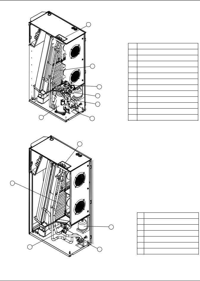
1.0LIEBERT CRV COMPONENT LOCATION
Figure 1 Component location, common components—All models
|
7 |
13 |
2 |
|
|
|
|
1 |
Liebert iCOM® control display |
11 |
|
9 |
2 |
Electric box |
|
3 |
Evaporator / CW coil |
||
|
|
|
||
|
|
|
4 |
Condensate pump |
1 |
|
|
5 |
Electric heaters |
|
|
|
||
14 |
|
|
6 |
Humidifier distributor |
|
|
|
Top humidifier water supply, |
|
|
|
|
7 |
|
|
|
|
condensate pump drain |
|
|
|
|
|
|
8 |
5 |
|
8 |
Drain trays, two places |
3 |
6 |
|
9 |
EC plug fans |
|
10 |
Bottom electrical entrance |
||
8 |
|
|
||
12 |
|
|
11 |
Serial tag inside door |
10 |
Rear |
|
12 |
Bottom condensate pump drain |
|
13 |
Top electrical entrance |
||
Front |
|
|
||
|
|
|
14 |
Supply air temperature sensor |
4 |
|
|
location (sensor not shown) |
|
|
|
|
Figure 2 Component location - Liebert CR035RA, CR020RA air-cooled units
9
|
|
|
|
1 |
Thermostatic expansion valve |
|
|
|
|
|
2 |
Solenoid valve |
|
|
|
|
7 |
3 |
Sight glass |
|
12 |
|
|
|
4 |
Filter dryer |
|
|
|
|
5 |
7 |
Humidity/temperature sensor |
|
|
|
|
8 |
Humidifier |
||
|
|
|
|
|||
|
|
|
6 |
9 |
Top refrigerant connections |
|
Front |
|
|
|
10 |
Bottom refrigerant connections |
|
|
|
|
4 |
11 |
Bottom humidifier water supply |
|
|
|
|
3 |
12 |
Air filters |
|
|
|
|
8 |
13 |
Bottom drain |
|
|
|
|
14 |
Compressor |
||
13 |
1 |
11 |
2 |
|||
15 |
Vibasorber |
|||||
|
|
|
||||
|
Rear |
10 |
|
|||
|
|
|
|
Liebert® CRV™ |
4 |
Liebert CRV Component Location
Figure 3 Component location - Liebert CR035RW, CR020RW water/glycol-cooled units
1
|
|
1 |
Top water/glycol connections |
|
|
2 |
Compressor |
|
|
3 |
Brazed plate condenser |
|
7 |
4 |
Bottom water/glycol connections |
|
5 |
Water/glycol valve |
|
|
|
||
|
|
6 |
Refrigerant receiver |
|
|
7 |
Air filters |
|
6 |
8 |
Vibasorber |
|
3 |
9 |
Thermostatic expansion valve |
|
10 |
Sight glass |
|
|
|
||
|
5 |
11 |
Filter dryer |
|
|
12 |
Humidity/temperature sensor |
2 |
4 |
13 |
Bottom humidifier water supply |
|
|
|
Figure 4 Component location - Liebert CR040RC chilled water units
1
2 
|
|
1 |
Top CW connections |
|
|
|
2 |
Air filters |
|
|
5 |
3 |
Three-way CW valve |
|
|
|
4 |
Bottom CW connections |
|
|
|
5 |
Humidifier |
|
3 |
4 |
6 |
Humidity/temperature sensor |
|
7 |
Bottom humidifier water supply |
|||
|
||||
|
|
5 |
Liebert® CRV™ |
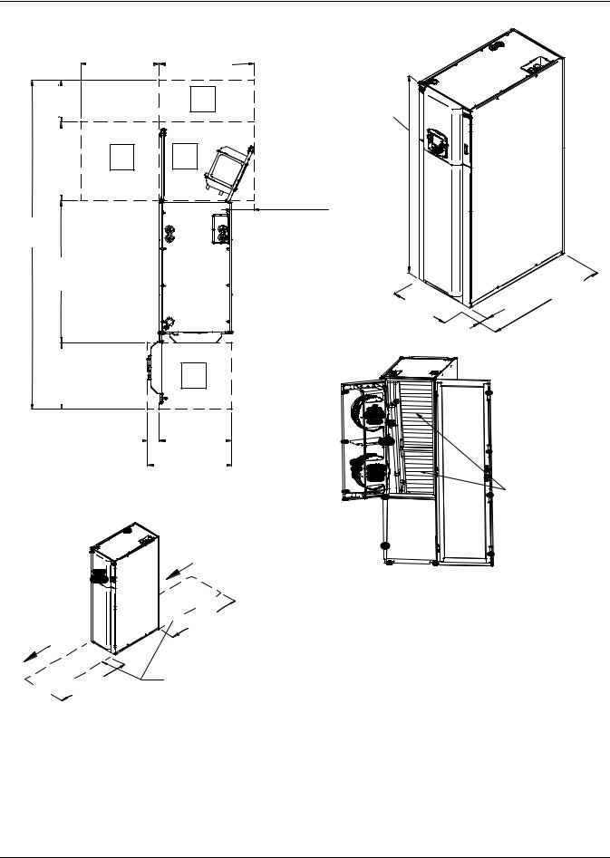
Liebert CRV Component Location
Figure 5 Overall dimensions / service area
|
25-9/16" |
35-9/16" |
|
(650mm) |
(903mm) |
13-3/4" |
|
A |
(350mm) |
|
|
25-9/16" |
B |
S |
(650mm) |
||
|
|
3-15/16" |
|
|
(100mm) |
107-5/16" |
|
Door Fully Open |
|
12" |
|
(2725mm) |
|
|
|
(305mm) |
|
|
|
|
46-1/4" |
|
|
(1175mm) |
|
Top |
|
|
|
21-5/8" |
|
S |
(550mm) |
|
|
3-15/16" (100mm) |
23-5/8" |
|
(600mm) |
||
|
|
27-9/16" |
|
|
(700mm) |
Access Required to Remove / Install
Entire Unit Within The Row
Cold Air
|
|
l |
|
|
|
l |
|
|
a |
|
|
t |
|
49" |
|
In |
|
|
|
s |
|
|
|

 (1245mm)
Hot Air
|
|
l |
|
|
|
l |
|
|
a |
|
|
t |
|
|
|
s |
|
49" |
|
In |
|
|
|
 (1245mm)
Only front or back clearance required
78-3/4" |
|
|
|
(2000mm) |
|
|
|
|
|
Rear |
|
Front |
|
|
|
|
3" |
46-1/4" |
|
23-5/8" |
(1175mm) |
||
(75mm) |
|||
(600mm) |
|
||
|
|
Air |
Filters |
Rear
DPN1791
Rev. 2
Table 1 |
Dry weight, all model types, ± 5% |
|||
|
|
|
|
|
|
|
|
Model Type |
|
|
|
Air Cooled |
Water/Glycol |
Chilled Water |
Model No. |
|
lb (kg) |
lb (kg) |
lb (kg) |
CR020R |
|
739 (335) |
772 (350 |
— |
CR035R |
|
805 (365) |
849 (385) |
— |
CR040R |
|
— |
— |
728 (330) |
Source: DPN001791, Rev. 2
Liebert® CRV™ |
6 |
Introduction
2.0INTRODUCTION
2.1Product Description
The Liebert CRV is a precision cooling unit available in compressorized (air-, wateror glycol-cooled) and chilled water configurations to be installed within a row of high-density computing racks in a “hot aisle-cold aisle” configuration.
Air enters the rear of the Liebert CRV from the hot aisle, is filtered, cooled and conditioned, then discharged into the cold aisle. The Liebert CRV provides all the necessary functions of a standard precision air conditioner, including cooling, heating, humidification, dehumidification, air filtration, condensate management, temperature control, alarm monitoring and data communication. The Liebert CRV is optimized for maximum cooling capacity in a minimal footprint.
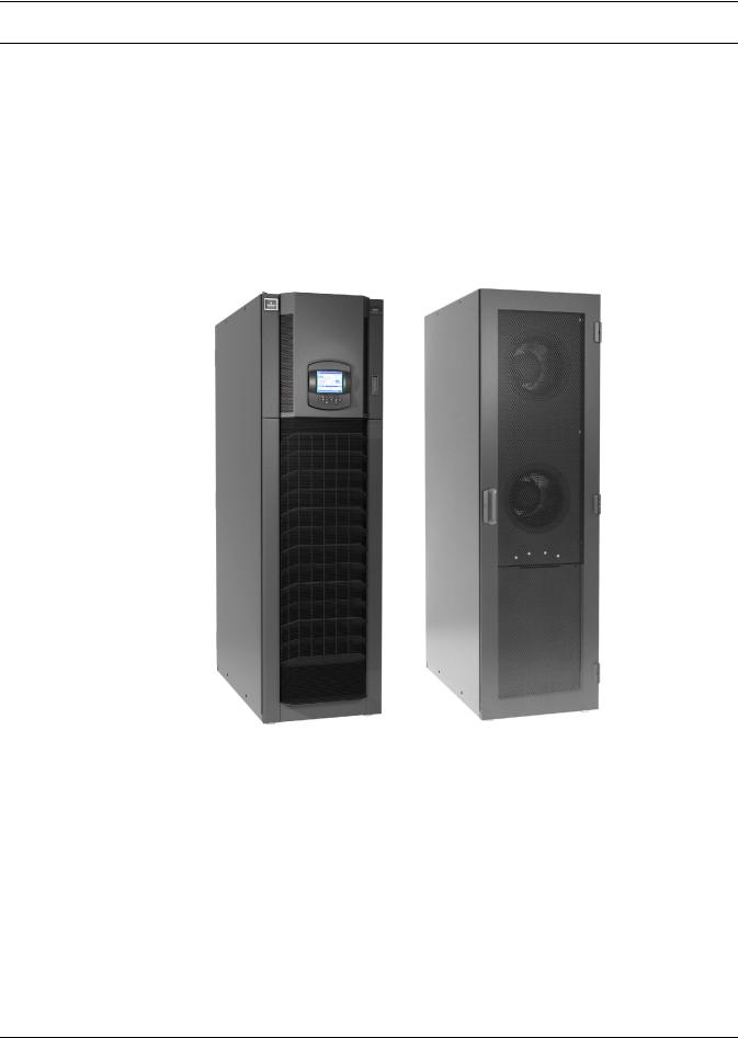
Figure 6 Liebert CRV, front and rear views
Front |
Rear |
7 |
Liebert® CRV™ |
Inspection and Unpacking
3.0INSPECTION AND UNPACKING
! WARNING
Risk of top-heavy unit falling over. Can cause equipment damage, personal injury and death.
Read all of the following instructions before attempting to move, lift or remove packaging from the Liebert CRV.
! CAUTION
Risk of sharp edges, splinters and exposed fasteners. Can cause personal injury.
Only properly trained and qualified personnel wearing appropriate safety headgear, gloves, shoes and glasses should attempt to move, lift or remove packaging from the Liebert CRV or prepare the unit for installation.
NOTICE
Risk of overhead interference. Can cause unit and/or building damage.
The unit may be too tall to fit through a doorway while on the skid. Measure the unit and doorway heights and refer to the installation plans prior to moving the unit to verify clearances.
NOTICE
Risk of improper storage. Can cause unit damage.
Keep the unit upright, indoors and protected from dampness, freezing temperatures and contact damage.
3.1Equipment Inspection
After the Liebert CRV unit arrives and before it is unpacked, verify that the delivered equipment matches the bill of lading. Examine the packaging for any signs of mishandling or damage. Inspect all items for damage, visible or concealed. Report any damage immediately to the carrier and file a damage claim. Send a copy of the claim to Emerson Network Power or your Emerson representative.
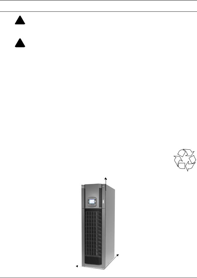
3.1.1Packing Material
All material used to package this unit is recyclable. Please save this material for future
use or dispose of it appropriately. R
3.2 Handling
Figure 7 Liebert CRV center of gravity
Z
X
Y
Liebert® CRV™ |
8 |
Inspection and Unpacking
•Always keep the packaged Liebert CRV upright and never leave it outdoors.
•Be aware of the center of gravity indicated on the package and in Table 2 below:
Table 2 |
Center of gravity |
|
|
|
|
|
|
|
|
|
|
Distance from lower right front corner, ± 2 in. (51m) |
||
Model no. |
|
|
|
|
|
X, in. (mm) |
Y, in. (mm) |
Z, in. (mm) |
|
|
|
|
|
|
CR020 |
|
20 (508) |
12 (305) |
28 (711) |
CR035 |
|
20 (508) |
12 (305) |
32 (813) |
CR040 |
|
21 (533) |
12 (305) |
32 (813) |
The center of gravity on the Liebert CRV varies with the options and the model's size.
Table 3 |
|
Weights without packaging |
|
|
|
|
|
|||||
|
|
|
|
|
|
|
|
|
|
|
|
|
Model |
|
Electrical |
|
|
|
Weight ± 5%, lb (kg) |
|
|
|
|
|
|
|
|
|
|
|
|
|
|
|
|
|
||
No. |
|
Data |
Air-Cooled |
Water/Glycol-Cooled |
Chilled Water |
|
|
|
||||
CR020 |
460/3/60 |
739 (335) |
|
772 (350) |
— |
|
|
|
||||
208/3/60 |
739 (335) |
|
772 (350) |
— |
|
|
|
|||||
|
|
|
|
|
||||||||
CR035 |
460/3/60 |
805 (365) |
|
849 (385) |
— |
|
|
|
||||
208/3/60 |
805 (365) |
|
849 (385) |
— |
|
|
|
|||||
|
|
|
|
|
||||||||
CR040 |
460/3/60 |
|
— |
|
|
— |
728 (330) |
|
|
|
|
|
208/3/60 |
|
— |
|
|
— |
728 (330) |
|
|
|
|
||
|
|
|
|
|
|
|
|
|||||
Table 4 |
|
Shipping weights |
|
|
|
|
|
|
|
|||
|
|
|
|
|
|
|
|
|||||
Model |
|
Domestic Packaging, lb (kg) |
Export Packaging, lb (kg) |
|||||||||
|
|
|
|
|
|
|
|
|
|
|
|
|
No. |
|
Air |
|
Water/Glycol |
|
Chilled Water |
Air |
|
Water/Glycol |
Chilled Water |
||
CR020 |
|
846 (384) |
|
879 (399) |
|
— |
953 (432) |
|
986 (447) |
— |
||
CR035 |
|
912 (414) |
|
956 (434) |
|
— |
1019 (462) |
|
1063 (482) |
— |
||
CR040 |
|
— |
|
— |
|
835 (379) |
— |
|
|
— |
942 (427) |
|
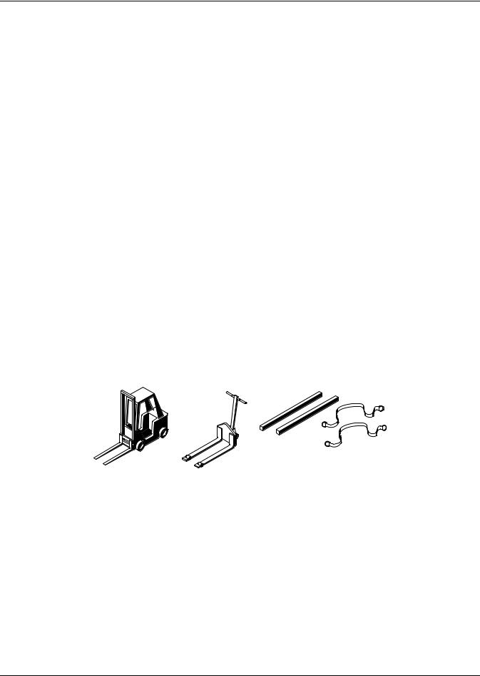
3.2.1 Handling the Unit While it is Packaged
Figure 8 Recommended unit handling equipment
|
Spreader Bars |
Forklift |
and Slings |
|
Pallet Jack |
•Transport the packaged unit using a forklift, pallet jack or by overhead lift with slings and spreader bars that are rated for the weight of the unit (see tables above).
•When using a forklift or pallet jack, make sure the forks (if adjustable) are spread to the widest allowable distance to still fit under the skid. Make sure the fork length is suitable for the skid length. Skid length is 60" (1524mm).
•Do not lift the packaged unit any higher than 4" (102mm). All personnel except those moving the Liebert CRV must be kept 12' (3.7m) or more from the unit while it is being moved.
•If the unit must be lifted higher than 4" (102mm) all personnel not directly involved in moving the Liebert CRV must be 20' (5m) or more from the unit.
9 |
Liebert® CRV™ |

Inspection and Unpacking
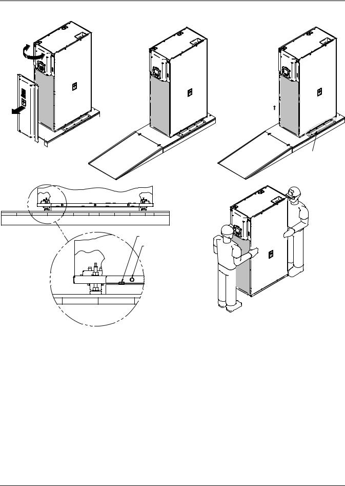
3.3Moving the Unit Using Rigging
! CAUTION
Risk of sharp edges, splinters and exposed fasteners. Can cause personal injury.
Only properly trained and qualified personnel wearing appropriate safety headgear, gloves, shoes and glasses should attempt to move, lift or remove packaging from the Liebert CRV or prepare the unit for installation.
1.Use a pallet jack or forklift to raise the packaged unit.
2.Place slings under the skid runners, equally spacing the slings to make sure the unit is balanced (see Figure 9).
3.Lower the unit and remove the pallet jack or forklift.
4.Connect the slings to the lifting device, using spreader bars or similar equipment to protect the unit (see Figure 9).
NOTE
Wrapping one or two more straps around the middle of the Liebert CRV will improve stability when it is lifted.
5.Move the unit to its installation location. Two or more properly trained and qualified personnel are required to move the Liebert CRV to its installation location.
6.Lower the Liebert CRV and remove the slings.
Figure 9 Moving the unit using rigging
197023 Rev. 4
3.4Unpacking the Liebert CRV
1.Remove the lag bolts securing ramp to skid.
2.Place the ramp and and the plastic bag with orange clips to the side for use in removing the unit from the skid.
3.Remove the stretch film and corner/side packaging planks from around the unit.
4.Remove the unit bag when ready to install the unit.
Liebert® CRV™ |
10 |

Inspection and Unpacking
Figure 10 Unpacking the Liebert CRV
197023 Rev. 4
3.5Removing the Unit from the Skid
! WARNING
Risk of top-heavy unit falling over. Can cause equipment damage, personal injury and death.
Read all of the following instructions before attempting to move, lift or remove packaging from the Liebert CRV.
! CAUTION
Risk of sharp edges, splinters and exposed fasteners. Can cause personal injury.
Only properly trained and qualified personnel wearing appropriate safety headgear, gloves, shoes and glasses should attempt to move, lift or remove packaging from the Liebert CRV or prepare the unit for installation.
1.Open the top panel door with the mounted control (refer to Figure 11).
2.Remove the bottom baffle panel assembly by removing the screws with a T30 Torx screwdriver.
3.Set the baffle panel assembly aside until the Liebert CRV is ready for it to be to reattached.
4.Close and latch the top panel door.
5.Place the ramp against the skid as shown in Figure 11.
6.Remove the orange clips from the plastic bag.
7.Insert clips into holes of the skid and ramp.
8.Remove the eight bolts, four on each side, that secure side tie-down brackets to skid. Bolts can be removed using a 17mm socket wrench, open-end wrench or pliers.
9.Lower the four stabilizer feet until the side tie-down brackets no longer contact the skid.
10.Remove the six bolts, three on each side), that secure the side tie-down brackets to the unit base. The bolts can be removed using a 13mm socket wrench, open-end wrench or pliers.
11.Remove the side tie-down brackets.
12.Remove the eight bolts, four on each side, that secure the lift block to the skid. The bolts can be removed using a 17mm socket wrench, open-end wrench or pliers.
13.Remove the lift blocks from the skid.
14.Using the stabilizer feet, lower the unit to the skid.
15.Move the unit to its installation location. Two or more properly trained and qualified personnel are required to move the Liebert CRV to its installation location.
11 |
Liebert® CRV™ |
Inspection and Unpacking
Figure 11 Removing the unit from the skid
Step 5
Step 1


Step 8
4 Bolts on Each Side Secure the Tie-Down Bracket to the Skid
M17 Socket
M13 Socket
Step 8
Step 15
197023 Rev. 4
3.6Reattach the Baffle Panel
Once the Liebert CRV has been moved to where it will be installed, the baffle panel can be reattached.
1.Open top panel door (the one with the Liebert iCOM®).
2.Reattach the bottom baffle panel assembly with screws, using a T30 Torx drive.
3.Close and latch top panel door.
Liebert® CRV™ |
12 |
Prepare the Liebert CRV for Installation
4.0PREPARE THE LIEBERT CRV FOR INSTALLATION
1.Open the display door and remove the lower front baffle panel using a 10mm nutdriver or T30 Torx Bit to prepare for installation.
2.Open the rear panel, referring to Figure 10. The documents are located inside the display door.
3.After the Liebert CRV is in its final installation position, adjust the four base supports, or feet, with an adjustable wrench. Ensure that the unit is level to avoid corrosion or health hazards caused by condensate accumulation.
a.Turning the base supports, or feet, clockwise, will extend them, lifting the unit one corner at a time.
b.Tighten the nut on the top of each adjustable foot, inside the Liebert CRV, to lock the feet.
Figure 12 Adjust leveling feet
Tighten this nut after the foot is adjusted to the desired height
Adjust the height of the feet
13 |
Liebert® CRV™ |

Piping
5.0PIPING
All fluid and refrigeration connections to the unit, with the exception of the condensate drain, are sweat copper. Factory-installed piping brackets must not be removed. Field-installed piping must be installed in accordance with local codes and must be properly assembled, supported, isolated and insulated. Avoid piping runs through noise-sensitive areas, such as office walls and conference rooms.
Refer to specific text and detailed diagrams in this manual for other unit-specific piping requirements.
All piping below the elevated floor must be arranged so that it offers the least resistance to airflow. Careful planning of the piping layout under the raised floor is required to prevent the airflow from being blocked. When installing piping on the subfloor, Emerson recommends installing the pipes in a horizontal plane rather than stacked one above the other. Whenever possible, the pipes should be run parallel to the airflow.
5.1Fluid Connections
NOTICE
Risk of water leakage. Can cause severe property damage and loss of critical data center equipment.
This unit requires a water drain connection. It may require an external water supply to operate the humidifier. Improper installation, application and service practices can result in water leakage from the unit.
Do not locate the Liebert CRV directly above any equipment that could sustain water damage. Emerson recommends installing monitored leak detection equipment for the unit and supply lines.
Liebert® CRV™ |
14 |

Piping
5.1.1Condensate Piping—Field-Installed
•Do not reduce drain lines
•Do not expose drain line to freezing temperatures
•Drain line may contain boiling water. Use copper or other suitable material
•Drain line must comply with local building codes
•Emerson recommends installing under-floor leak detection equipment
Gravity Drain—Units Without Factory-Installed Condensate Pump
•3/4" FPT drain connection is provided on units without optional factory-installed condensate pump with infrared humidifier or no humidifier; 1-1/4" FPT connection is provided on units with steam generating humidifier
•Pitch the drain line toward the drain a minimum of 1/8" (3mm) per 1 foot (305mm) of length
•Drain is trapped internally. Do not trap the drain external to equipment
•Drain line must be sized for 2 gpm (7.6 l/m) flow
NOTICE
Risk of improper piping connections. Can cause damage to the equipment and to the building.
The drain line has an internal trap and must not be trapped outside the unit or water may back up into the drain pan and overflow the unit cabinet.
Figure 13 Gravity drain
Internal
Drain
UNIT

 External
Drain
Continuous Downward Slope
CORRECT
UNIT |
Internal |
Drain |
|
External |
Do Not Externally |
Drain |
Trap the Unit |
|
INCORRECT
Condensate Pump
|
Internal |
|
UNIT |
Drain |
|
|
External |
|
These are external traps also, although |
Drain |
|
|
||
unintentional. Lines must be rigid enough |
|
|
not to bow over top of other objects. |
DPN001556 |
|
INCORRECT |
||
Rev. 0 |
•1/2" copper sweat connection is provided on units with optional factory-installed condensate pump
•Condensate pump is rated for approximately 6 GPM (22.7 l/min) at 30 ft (9m) total head
•Size piping based on available condensate head
5.1.2Humidifier Supply Water—Optional Steam Generating Canister
•1/4" supply line; maximum water pressure is 145psi (1000kPa)
•Fill valve is sized for pressure range of 30 to 120psi (207-827kPa)
•Do not supply steam generating humidifier with softened water
•Do not use hot water source
•Water conductivity must be in the range of 330-670 micro-siemens
15 |
Liebert® CRV™ |

Piping
5.1.3Requirements of Systems Using Water or Glycol
These guidelines apply to the field leak checking and fluid requirements for field piping systems, including Liebert chilled water, condenser (water or glycol) and drycooler circuits.
General Guidelines
•Equipment damage and personal injury can result from improper piping installation, leak checking, fluid chemistry and fluid maintenance.
•Follow local piping codes, safety codes.
•Qualified personnel must install and inspect system piping.
•Contact a local water consultant regarding water quality, corrosion protection and freeze protection requirements.
•Install manual shutoff valves at the supply and return line to each indoor unit and drycooler to permit routine service and emergency isolation of the unit.
NOTICE
Risk of frozen fluids. Can cause equipment damage and building damage.
Freezing system fluids can rupture piping. Complete system drain-down cannot be ensured. When the field piping or unit may be exposed to freezing temperatures, charge the system with the proper percentage of glycol and water for the coldest design ambient.
Automotive antifreeze is unacceptable and must NOT be used in any glycol fluid system.
NOTICE
Risk of corrosion. Can cause equipment damage.
Read and follow individual unit installation instructions for precautions regarding fluid system design, material selection and use of field-provided devices. Liebert systems contain iron and copper alloys that require appropriate corrosion protection.
Contact a local water consultant regarding water quality, corrosion and freeze protection requirements.
Water chemistry varies greatly by location, as do the required additives, called inhibitors, that reduce the corrosive effect of the fluids on the piping systems and components. The chemistry of the water used must be considered, because water from some sources may contain corrosive elements that reduce the effectiveness of the inhibited formulation. Sediment deposits prevent the formation of a protective oxide layer on the inside of the coolant system components and piping. The water/coolant fluid must be treated and circulating through the system continuously to prevent the build up of sediment deposits and or growth of sulfate reducing bacteria.
Preferably, surface waters that are classified as soft and are low in chloride and sulfate ion content should be employed. Proper inhibitor maintenance must be performed in order to prevent corrosion of the system. Consult glycol manufacturer for testing and maintenance of inhibitors.
Commercial ethylene glycol (Union Carbide Ucartherm, Dow Chemical Dowtherm SR-1 and Texaco E.G. Heat Transfer Fluid 100), when pure, is generally less corrosive to the common metals of construction than water itself. It will, however, assume the corrosivity of the water from which it is prepared and may become increasingly corrosive with use if not properly inhibited.
NOTICE
Risk of no-flow condition. Can cause equipment damage. Do not leave the unit in a no-flow condition.
Idle fluid allows the collection of sediment that prevents the formation of a protective oxide layer on the inside of tubes. Keep unit switched ON and system pump operating.
Liebert® CRV™ |
16 |

Piping
Leak Checking of Unit and Field Piping
Liebert unit fluid systems are factory-checked for leaks and may be shipped with a nitrogen holding charge. Liebert unit fluid circuits should be checked for leaks at installation as described below.
NOTE
During leak checking of field-installed piping, Emerson recommends that the unit be isolated using field-installed shutoff valves. When the Liebert units are included in a leak test, use of fluid for pressure testing is recommended. When pressurized gas is used for leak testing the Liebert unit, the maximum recommended pressure is 30 psig (2 bars) and tightness of the unit should be verified by pressure decay over time, (<2 psig/hour [0.3 bars/hour]) or sensing a tracer gas with suitable instrumentation. Dry seals in fluid valves and pumps may not hold a high gas pressure.
17 |
Liebert® CRV™ |
Refrigerant Connections
6.0REFRIGERANT CONNECTIONS
! WARNING
Risk of explosive discharge from high-pressure refrigerant. Can cause injury or death. This unit contains fluids and/or gases under high pressure.
Relieve pressure before working with piping.
! WARNING
Risk of refrigerant system rupture or explosion from overpressurization. Can cause equipment damage, injury and death.
A pressure relief valve is required for compliance with the EU Pressure Equipment Directive and may be required for compliance with local codes. If a discharge pressure relief device is not provided with the condenser unit, the system installer must install one in the high side of the refrigerant circuit and rated for a maximum of:
•675psig (46.5bar) for water/glycol-cooled units
•700psig (48.3bar) for air-cooled units
A shutoff valve must not be installed between the compressor and the field-installed relief valve.
One or more additional pressure relief valves are required downstream of any and all field-installed isolation. Do not isolate any refrigerant circuits from overpressurization protection.
NOTICE
Risk of oil contamination with water. Can cause equipment damage.
The piping must not be open to the atmosphere for extended periods because the Liebert CRV requires POE (polyol ester) oil. POE oil absorbs water at a much faster rate when exposed to air than previously used oils. Because water is the enemy of a reliable refrigeration system, extreme care must be used when opening systems during installation or service. If water is absorbed into the POE oil, it will not be easily removed and will not be removed through the normal evacuation process. If the oil is too wet, it may require an oil change. POE oils also have a property that makes them act as a solvent in a refrigeration system. Maintaining system cleanliness is extremely important because the oil will tend to bring any foreign matter back to the compressor.
The Liebert CRV can be connected to a condenser through either the top or bottom of the unit. The unit is piped for connections at the top of the unit as shown in Figure 14, with provision for connection through the bottom of the unit.
Connecting through the bottom of the unit requires cutting the liquid and suction lines as shown in Figure 15. Cutting these lines disconnects the top connections from the rest of the refrigeration system.
Air-cooled units are shipped with a holding charge of nitrogen.
Liebert® CRV™ |
18 |
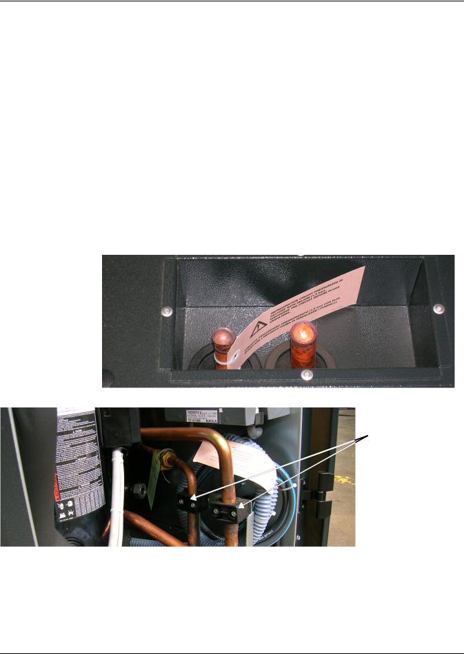
Refrigerant Connections
6.1Piping Guidelines—Air-Cooled Units
•Indoor unit ships with a nitrogen holding charge; do not vent the evaporator until all refrigerant piping is in place, ready for connection to the unit and condenser
•Use copper piping with high temperature brazed joints
•Isolate piping from building using vibration-isolating supports
•Refer to Tables 7 through 10 for piping sizes
•Refer to condenser installation manual for charging information
•Install traps on hot gas (discharge) lines at the base of vertical risers and every 15 feet (4.6m) of vertical rise.
•See Table 6 for the allowable elevation difference between the condenser and the Liebert CRV.
•Consult factory if piping run exceeds 300 feet (91m) equivalent length
•Keep piping clean and dry, especially on units with R-410A refrigerant
•Avoid piping runs through noise-sensitive areas
•Do not run piping directly in front of airstream of any air conditioner
•Refrigerant oil – do not mix oil types
Refer to ASHRAE Refrigeration Handbook for general, good-practice refrigeration piping.
6.2Refrigerant Piping—Air-Cooled Models
Figure 14 Top refrigerant piping connections
Figure 15 Bottom refrigerant piping connections
If using bottom connections, cut the pipes just below the black pipe clamps
19 |
Liebert® CRV™ |

Refrigerant Connections
6.2.1General Layout
1. Piping must be Type ACR copper tubing and sized per Tables 7, 8, 9 and 10.
NOTE
All field-installed piping must comply with applicable national, state and local codes.
Use the shortest possible refrigeration pipelines to minimize the total charge of refrigerant and the number of pressure drops.
2.Minimize the number of bends and make the bends the largest radius practical to prevent constricting refrigerant flow.
3.Insulate the piping as specified in Table 5. If the pipes are installed next to electrical cables, they must be isolated from the building using vibration-isolating supports to avoid damage to cable insulation.
4.There must be at least one inch (25mm) separation between the gas and liquid pipelines. If this is not possible, insulate both lines.
5.Support both horizontal and vertical pipes with vibration-damping clamps, which include rubber gaskets. Place these clamps every 5 to 7 ft. (1.5 to 2m).
Table 5 Condenser positioning
Condenser
Position
Discharge
Line
Insulation
Liquid
Line
Layout
** See Table 6
|
Condenser Above |
|||
|
Liebert CRV |
|||
Indoor |
necessary |
|||
Outdoor |
only for aesthetic reasons |
|||
Indoor |
only for aesthetic reasons |
|||
Outdoor |
only for aesthetic reasons |
|||
|
|
|
|
|
|
|
|
|
|
(See**) |
Gas |
Liquid |
Room Unit |
|
|||
15 ft. (4.6m) |
(See *) |
|
|
* Oil traps every 15 ft. (4.6m) of vertical piping
Condenser and |
Condenser Below |
Liebert CRV |
Liebert CRV |
at Same Level |
(Not Recommended) |
necessary |
necessary |
only for aesthetic reasons |
only for aesthetic reasons |
only for aesthetic reasons |
no (expose to cold under-floor air) |
only if exposed to sun |
only if exposed to sun |
Room Unit
Room Unit
|
Liquid |
(See**) |
Gas |
|
|
Liquid |
|
|
Table 6 |
Liebert CRV position relative to the remote condenser |
||
|
|
|
|
|
Parameter |
Maximum Distances, ft. (m) |
|
|
|
||
From Liebert CRV to condenser |
300 (91.4) equivalent length |
||
|
|
|
|
From Liebert CRV to VFD condenser |
Above: 60 (18.3) |
Below: 15 (4.5) |
|
|
|
|
|
From Liebert CRV to Liebert Lee-Temp™ condenser |
Above: 60 (18.3) |
Below: 0 (0) |
|
Requirements |
|
|
|
|
|
|
|
Oil traps on vertical line of gas refrigerant |
Every 15 (4.6) |
||
|
|
|
|
Liebert® CRV™ |
20 |

Refrigerant Connections
Figure 16 Pipeline air conditioner - condenser
C |
|
COND |
|
(Distance) D = A + B + C CDT |
B |
|
|
CDT = Conditioner |
|
COND = Condenser |
A |
|
6.2.2Pipe Diameter and Thickness
!
Table 7
WARNING
Risk of explosive discharge. Can cause equipment damage, injury or death.
Use only Type ACR copper tubing sized per Tables 7, 8, 9 and 10 for pipes connecting the Liebert CRV and the condensing unit.
Piping and refrigerant sizes for Liebert Lee-Temp™ condensers with R-410A
Condenser Piping Connection Sizes
Condenser Connections, O.D., in. |
|
Liebert Lee-Temp Connections, I.D., in. |
||||
|
|
|
|
|
|
|
|
|
|
Liebert Lee-Temp |
Hot Gas |
Liquid To |
Receiver |
Condenser Model # |
Hot Gas |
Liquid |
Size, in. (mm) |
Tee |
L-T Valve |
Out |
DCSL28K |
1-1/8 |
7/8 |
9 x 36 (229 x 914) |
1-1/8 |
5/8 |
7/8 |
|
|
|
|
|
|
|
DCSL60K |
1-1/8 |
7/8 |
11 x 36 (279 x 914) |
1-1/8 |
5/8 |
7/8 |
|
|
|
|
|
|
|
DCSL90K |
1-1/8 |
7/8 |
11 x 48 (279 x 1219) |
1-1/8 |
5/8 |
7/8 |
|
|
|
|
|
|
|
Source: DPN001623, Rev. 6, Page 3
Table 8 |
Recommended refrigerant line sizes for Liebert Lee-Temp condensers with R-410A Cu, OD |
||||
|
|
|
|
|
|
|
|
Total Equivalent |
Hot Gas Line, |
Liquid Line, |
|
Liebert CRV Model # |
Length, ft. (m) |
in. (mm) |
in. (mm) |
|
|
|
|
50 (15.2) |
3/4 (19.1) |
5/8 (15.9) |
|
|
|
|
|
|
|
CR020RA |
100 (30.5) |
3/4 (19.1) |
5/8 (15.9) |
|
|
|
|
|
|
||
150 (45.7) |
3/4 (19.1) |
5/8 (15.9) |
|
||
|
|
|
|||
|
|
|
|
|
|
|
|
300 (91.4) |
7/8 (22.2)* |
3/4 (19.1) |
|
|
|
|
|
|
|
|
|
50 (15.2) |
7/8 (22.2) |
3/4 (19.1) |
|
|
|
|
|
|
|
CR035RA |
100 (30.5) |
7/8 (22.2) |
3/4 (19.1) |
|
|
|
|
|
|
||
150 (45.7) |
7/8 (22.2) |
3/4 (19.1) |
|
||
|
|
|
|||
|
|
|
|
|
|
|
|
300 (91.4) |
1-1/8 (28.6)* |
7/8 (22.2) |
|
|
|
|
|
|
|
Consult factory for proper line sizing for runs longer than 300 ft. (91.4m) equivalent length. * Must downsize vertical riser one trade size (1-1/8” to 7/8” or 7/8” to 3/4”).
Source: DPN001623, Rev. 6, Page 3
21 |
Liebert® CRV™ |

Refrigerant Connections
Table 9 Piping and refrigerant sizes for Liebert air-cooled, VFD control condensers with R-410A
Condenser Piping Connection Sizes, Cu, O.D.
|
Entering Hot Gas |
Returning Liquid |
Condenser Model # |
Line, in. (mm) |
Line, in. (mm) |
|
|
|
TCSV28K |
1-1/8 (28.6) |
7/8 (22.2) |
|
|
|
TCSV60K |
1-1/8 (28.6) |
7/8 (22.2) |
|
|
|
TCSV90K |
1-1/8 (28.6) |
7/8 (22.2) |
|
|
|
Source: DPN001624, Rev. 5, Page 3
Table 10 Recommended refrigerant line sizes for Liebert air-cooled, VFD control condensers with R-410A, Cu, OD
|
Total Equivalent |
Hot Gas Line, |
Liquid Line, |
|
Liebert CRV Model # |
Length, ft. (m) |
in. (m) |
in. (m) |
|
|
|
|
|
|
|
50 (15.2) |
3/4 (19.1) |
5/8 (15.9) |
|
|
|
|
|
|
CR020RA |
100 (30.5) |
3/4 (19.1) |
5/8 (15.9) |
|
|
|
|
||
150 (45.7) |
3/4 (19.1) |
5/8 (15.9) |
||
|
||||
|
|
|
|
|
|
300 (91.4) |
7/8 (22.2) 2 |
3/4 (19.1) |
|
|
50 (15.2) |
7/8 (22.2) |
3/4 (19.1) |
|
|
|
|
|
|
CR035RA |
100 (30.5) |
7/8 (22.2) |
3/4 (19.1) |
|
|
|
|
||
150 (45.7) |
7/8 (22.2) |
3/4 (19.1) |
||
|
||||
|
|
|
|
|
|
300 (91.4) |
1-1/8 (28.6) 2 |
7/8 (22.2) |
1.Consult factory for proper line sizing for runs longer than 300 ft. (91.4m) equivalent length.
2.Must downsize vertical riser one trade size (1-1/8" to 7/8" or 7/8" to 3/4" ).
Source: DPN001624, Rev. 5, Page 3
Liebert® CRV™ |
22 |
Loading...