


READ AND SAVE THESE INSTRUCTIONS
Ceiling Fan Light Fixture
Owner’s Manual
Model Numbers:
LK70 & LK80
Includes: Three 13-Watt CFL Bulbs
and F480WW Fitter
Net Weight: 3.5 Lbs.
U® L
Part No. F40BP74180000 |
Form No. BP7418 |
Safety Instructions
WARNING: To avoid fire, shock, and serious personal injury, follow all instructions carefully.
1.Read your Owner's Manual carefully before installing the light fixture. Retain Owner's Manual for future reference.
2.Be careful of the fan and blades when cleaning, painting, or working near the fan. Before installing or servicing the light fixture or ceiling fan, switch power off at service panel and lock service panel disconnecting means to prevent power from being switched on accidentally. When the service disconnecting means cannot be locked, securely fasten a warning device, such as a tag, to the service panel.
3.Do not exceed the wattage indicated on fixture.
ADDITIONAL SAFETY INSTRUCTIONS FOR INSTALLATION
1.To avoid possible electrical shock be sure electricity is turned off at the main fuse or circuit breaker box before wiring.
2.Make certain no bare wires are exposed outside the wire connectors.
3.All wiring must conform to national and local electrical codes.
4.Follow the recommended instructions for the proper method of wiring your new light fixture. If you feel you do not have enough electrical wiring knowledge or experience, have your light fixture installed by a licensed electrician. Any electrical work not described in this manual should be performed by a licensed electrician.
WARNING: To reduce the risk of possible fire and electrical shock, install only on Emerson CF Series Ceiling Fans.
Assembly and Installation
! WARNING
Do not install or use the light fixture if any part is missing or damaged. Contact your dealer for replacement.
! WARNING
To avoid possible electrical shock, be sure electricity is turned off at the main fuse or circuit breaker box before wiring.
Installation on Emerson Fans Having a Modular Switch Cup with Center Screw
1.Remove all parts and parts packages from the carton.
2.Remove the switch cup from the cover plate by removing the three screws around the side of the switch cup (Figure 1).
3.Disconnect the motor connector from the switch cup connector (Figure 1).
4.Remove the center screw from the switch cup (Figure 1).
5.Carefully locate the white and blue wires (labeled either "L" or "LIGHT") in the switch cup and remove the wire connectors from the wires.
6.Insert the black and white wires from the light fitter through the center hole in the switch cup (Figure 2) and thread the switch cup onto the light fitter. Hold wires taut while installing switch cup to prevent the wires from twisting. Tighten the fitter until the fan switch chain aligns with the hole in the fitter.
 COVER PLATE
MOTOR CONNECTOR
|
SWITCH CUP |
SCREWS |
CONNECTOR |
SWITCH
CUP
CENTER SCREW
Figure 1
7.If installing in a wet location: Install the light fitter on plate using the lockwasher, nut and rubber washer supplied with wet location plate. Place the rubber washer on the top of the wet location plate, then place the light fitter through the center hole of the wet location plate, secure with lockwasher and nut (Figure 2).
2

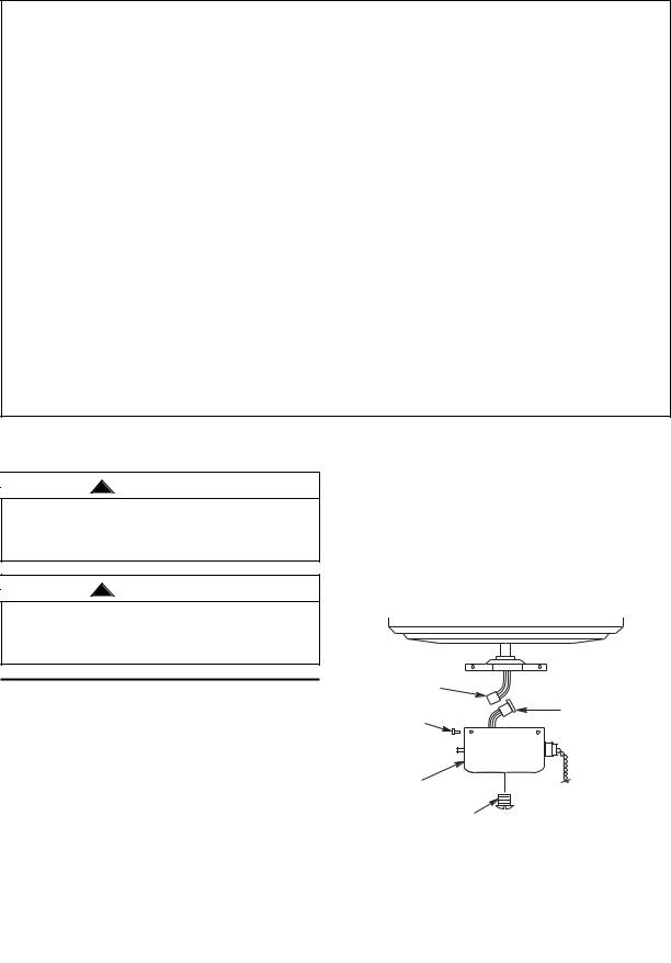
8.Insert the black and white wires through the lockwasher and hex nut (supplied), firmly tighten the hex nut to secure the light kit fitter to the switch cup. Connect the white wire from the switch cup to the white wire of the light fitter (Figure 2). Connect the blue wire from the switch cup to the black wire of the light fitter. Use listed wire connectors (previously removed in Step 5) to make connections (Figures 2 and 3).
9.Carefully tuck all wires and splices into the switch cup. (Figure 2.)
10.Connect the motor connector to the switch cup connector.
11.Position the cup/light fitter in the cover plate and install the three screws that were previously removed in Step 2 and tighten securely.
12.Install three 13-watt medium base compact fluorescent bulbs into the light sockets.
MOTOR |
COVER PLATE |
|
|
CONNECTOR |
SWITCH CUP |
|
|
BLACK WIRE |
CONNECTOR |
|
WIRE |
BLUE WIRE |
CONNECTOR |
|
|
HEX NUT |
WHITE WIRES |
SCREWS |
LOCKWASHER |
SWITCH CUP |
FAN SWITCH |
|
CHAIN |
|
HEX NUT |
|
LOCKWASHER |
|
WET LOCATION |
|
PLATE (sold |
|
separately) |
ADJUSTABLE |
LIGHT |
FITTER |
|
LIGHT FITTER |
BOWL CAP |
|
|
FINIAL |
FAN SWITCH |
CHAIN |
(sold separately)
Figure 2
WARNING: To avoid possible fire or electrical shock, make certain no bare wire strands are exposed outside wire connectors.
Figure 3
! WARNING
To avoid possible fire or electric shock, be careful not to pinch wires between switch cup and the cover plate.
NOTE: The FN100 finial pack (sold separately) comes with three options: no holes, one hole and two holes for pull chain options.
13.Depending on the model purchased, insert the fan speed control switch chain through the offset hole in the glass bowl or the hole in the bowl cap.
NOTE: Two finial nuts are supplied with FN100 kit. Use the taller finial nut when a frame is not being installed.
14.Gently place the glass bowl onto the light fixture (Figure 4). Then place the finial (sold separately) onto the threaded light fixture. Tighten the taller finial nut (supplied with finial) onto the threaded light fixture (Figure 4).
|
WET LOCATION |
|
PLATE |
|
(OPTIONAL) |
|
GLASS BOWL |
|
FINIAL (sold separately) |
|
FINIAL NUT (Taller Nut) |
Figure 4 |
(sold separately) |
|
15.If installing an optional frame: Gently slide the frame over the glass bowl then secure the frame to the light fixture by placing the hex nut, finial and shorter finial nut (both sold separately) onto the threads of the light fixture. Tighten the shorter finial nut onto the threaded light fixture (Figure 5).
|
WET LOCATION |
|
PLATE |
|
(OPTIONAL) |
|
GLASS BOWL |
|
FRAME (OPTIONAL) |
|
HEX NUT & FINIAL (sold separately) |
Figure 5 |
FINIAL NUT (Shorter Nut) |
(sold separately) |
NOTE: The 9” pull chain extending from the light fixture is without a chain coupling attached, two chain couplings are included and pre-installed to the 9” extension pull chain located in the parts bag.
16.Connect the wood pendant (supplied) to the switch pull chain by sliding the wood pendant (small hole first) onto the pull chain. Attach the chain coupling to the end of the chain and allow the wood pendant to fall down over the coupling.
NOTE: It is advisable to periodically check the tightness of the finial.
3
 Loading...