


 Loading...


 Precision Cooling


 For Business-Critical Continuity™


 Liebert® XDC™


 User Manual - 50 and 60 Hz, 130 & 160kW Nominal Cooling Capacity

GENERAL SAFETY GUIDELINES
Before beginning the installation of the Liebert XDC, read all instructions, verify that all the parts are included, and check the nameplate to be sure the Liebert XDC voltage matches available utility power.
Follow all local codes.
! WARNING
Risk of electric shock. Can cause injury or death.
Disconnect all local and remote electric power supplies before working within.
! WARNING
Risk of unit falling over. Can cause death, injury and equipment damage.
The Liebert XDC is top-heavy. Use extreme caution and care when moving and installing this unit.
! CAUTION
Risk of piping and component rupture. Can cause injury or equipment damage. Closing service valves may isolate liquid refrigerant, causing high pressure and rupture of piping. Do not close valves without following recommended procedures for repair, maintenance and replacement of components. Install pressure relief valves in field piping that may become isolated by service valves.
! WARNING
Risk of refrigerant system explosion or rupture from overpressurization. Can cause injury, death or equipment damage.
Installer must install a 400 psig pressure relief valve in each of the two R-407C refrigerant circuits of the Liebert XDC system. Do not install shutoff valves between the compressors and the pressure relief valves.
For systems requiring EU CE compliance, the pressure relief valves must be CE-certified by a notified body to the EU Pressure Equipment Directive.
! CAUTION
Risk of contact with hot surfaces. Can cause burn injury. The compressors and refrigerant discharge lines are extremely hot during unit operation. Allow sufficient time for the compressors and refrigerant discharge lines to cool before working within the unit cabinet. Use extreme caution and wear protective gloves and arm protection when working on or near hot compressor and discharge lines.
NOTE
This document shall be used together with site specific documentation and documentation for
other parts of the system (heat rejection devices and cooling modules).
NOTE
Before any action that could cause a disturbance in the XD system’s cooling function is begun,
the facility manager MUST be informed. In addition, after the action is taken and the work is finished, the facility manager MUST be informed.
Figure i Model number nomenclature
|
|
|
|
|
Example: XDC160AA– –* |
|
|
|
|
|
|
|||||
XD |
C |
160 |
A |
A |
– |
– |
* |
|||||||||
|
|
|
|
|
|
Place |
|
holder |
|
|
|
|
|
|
|
|
|
|
Chiller |
|
|
|
|
Place holder |
|
|
Revision |
||||||
|
|
unit |
|
|
|
|
|
|
|
|
|
|
|
level |
||
Liebert |
|
|
Model size |
|
|
|
A = 460V-3ph-60Hz |
Place holder |
|
|
||||||
X-treme heat |
|
|
|
|
|
|
|
(voltage-phase-frequency) |
|
|
|
|
||||
Density system |
|
|
|
|
|
|
|
M = 380/415-3ph-50Hz |
|
|
|
|
||||

TABLE OF CONTENTS
GENERAL SAFETY GUIDELINES . . . . . . . . . . . . . . . . . . . . . . . . . . . . . . . . . . . INSIDE FRONT COVER 1.0 PRODUCT DESCRIPTION . . . . . . . . . . . . . . . . . . . . . . . . . . . . . . . . . . . . . . . . . . . . . . . . . . .1
1.1 General Product Information. . . . . . . . . . . . . . . . . . . . . . . . . . . . . . . . . . . . . . . . . . . . . . . . . . . 1
1.1.1 Product/System Description. . . . . . . . . . . . . . . . . . . . . . . . . . . . . . . . . . . . . . . . . . . . . . . . . . . . . 1
1.2 Equipment Inspection . . . . . . . . . . . . . . . . . . . . . . . . . . . . . . . . . . . . . . . . . . . . . . . . . . . . . . . . 1 1.3 Equipment Handling . . . . . . . . . . . . . . . . . . . . . . . . . . . . . . . . . . . . . . . . . . . . . . . . . . . . . . . . . 1
1.3.1 Handling With Skid . . . . . . . . . . . . . . . . . . . . . . . . . . . . . . . . . . . . . . . . . . . . . . . . . . . . . . . . . . . 2 1.3.2 Removal of Skid . . . . . . . . . . . . . . . . . . . . . . . . . . . . . . . . . . . . . . . . . . . . . . . . . . . . . . . . . . . . . . 2 1.3.3 Removing Piano Jacks . . . . . . . . . . . . . . . . . . . . . . . . . . . . . . . . . . . . . . . . . . . . . . . . . . . . . . . . . 4
1.4 Mechanical Considerations . . . . . . . . . . . . . . . . . . . . . . . . . . . . . . . . . . . . . . . . . . . . . . . . . . . . 4
1.4.1 Positioning the Liebert XDC . . . . . . . . . . . . . . . . . . . . . . . . . . . . . . . . . . . . . . . . . . . . . . . . . . . . 4 1.4.2 Placing the Liebert XDC on a Floor Stand . . . . . . . . . . . . . . . . . . . . . . . . . . . . . . . . . . . . . . . . . 6 1.4.3 Positioning the Liebert XDC with Floor Stand. . . . . . . . . . . . . . . . . . . . . . . . . . . . . . . . . . . . . . 9
1.5 High Voltage Connections . . . . . . . . . . . . . . . . . . . . . . . . . . . . . . . . . . . . . . . . . . . . . . . . . . . . 10
1.5.1 Connecting High-Voltage Cables . . . . . . . . . . . . . . . . . . . . . . . . . . . . . . . . . . . . . . . . . . . . . . . . 10
1.6 Extra Low Voltage Connections . . . . . . . . . . . . . . . . . . . . . . . . . . . . . . . . . . . . . . . . . . . . . . . 13
2.0 PIPING AND FILLING WITH REFRIGERANT: R-134A AND R-407C CIRCUITS . . . . . . . . . . . . .16
2.1 European Union Fluorinated Greenhouse Gas Requirements . . . . . . . . . . . . . . . . . . . . . . . 16 2.2 Recommended Pipe Size. . . . . . . . . . . . . . . . . . . . . . . . . . . . . . . . . . . . . . . . . . . . . . . . . . . . . . 16 2.3 Liebert XDC Interconnection With Liebert XD Cooling Module . . . . . . . . . . . . . . . . . . . . . . 16 2.4 Piping Installation Method . . . . . . . . . . . . . . . . . . . . . . . . . . . . . . . . . . . . . . . . . . . . . . . . . . . 17
2.4.1 Piping Installation—R-134a Pumped Circuit . . . . . . . . . . . . . . . . . . . . . . . . . . . . . . . . . . . . . . 17
2.5 Filling the Pumped Circuit—R-134a. . . . . . . . . . . . . . . . . . . . . . . . . . . . . . . . . . . . . . . . . . . . 20
2.5.1 Calculating Refrigerant Charge—Example . . . . . . . . . . . . . . . . . . . . . . . . . . . . . . . . . . . . . . . 21 2.5.2 Piping for Direct Expansion (DX) Circuit—R-407C Air-Cooled Units . . . . . . . . . . . . . . . . . . 22
2.6 Install Double Discharge Risers . . . . . . . . . . . . . . . . . . . . . . . . . . . . . . . . . . . . . . . . . . . . . . . 22
2.6.1Air-Cooled Condenser with Liebert Lee-Temp “Flooded Condenser” Head Pressure
Control System—R-407C (DX) Circuit . . . . . . . . . . . . . . . . . . . . . . . . . . . . . . . . . . . . . . . . . . . 30
2.7 Filling the Direct Expansion (DX) Circuit—R-407C . . . . . . . . . . . . . . . . . . . . . . . . . . . . . . . 31
3.0 INSTALLATION CHECKLIST . . . . . . . . . . . . . . . . . . . . . . . . . . . . . . . . . . . . . . . . . . . . . . . .32 4.0 CHECKLIST FOR LIEBERT XDC STARTUP . . . . . . . . . . . . . . . . . . . . . . . . . . . . . . . . . . . . .33
4.1 System Refrigerant Charges Over 35 lb. (15.9kg) Require Additional Oil . . . . . . . . . . . . . . 34
4.1.1 Liebert XDC DX R-407C Circuit Volume . . . . . . . . . . . . . . . . . . . . . . . . . . . . . . . . . . . . . . . . . 34
5.0 MICROPROCESSOR CONTROL . . . . . . . . . . . . . . . . . . . . . . . . . . . . . . . . . . . . . . . . . . . . . .36
5.1 Feature Overview . . . . . . . . . . . . . . . . . . . . . . . . . . . . . . . . . . . . . . . . . . . . . . . . . . . . . . . . . . . 36
5.1.1 Display . . . . . . . . . . . . . . . . . . . . . . . . . . . . . . . . . . . . . . . . . . . . . . . . . . . . . . . . . . . . . . . . . . . . 36
i

5.2 Controls. . . . . . . . . . . . . . . . . . . . . . . . . . . . . . . . . . . . . . . . . . . . . . . . . . . . . . . . . . . . . . . . . . . 37
5.2.1 Feature Overview . . . . . . . . . . . . . . . . . . . . . . . . . . . . . . . . . . . . . . . . . . . . . . . . . . . . . . . . . . . . 37
5.2.2 Status Display . . . . . . . . . . . . . . . . . . . . . . . . . . . . . . . . . . . . . . . . . . . . . . . . . . . . . . . . . . . . . . 37
5.3 Main Menu . . . . . . . . . . . . . . . . . . . . . . . . . . . . . . . . . . . . . . . . . . . . . . . . . . . . . . . . . . . . . . . . 37
5.3.1 Viewing or Changing Settings . . . . . . . . . . . . . . . . . . . . . . . . . . . . . . . . . . . . . . . . . . . . . . . . . . 37
5.3.2 SETPOINTS . . . . . . . . . . . . . . . . . . . . . . . . . . . . . . . . . . . . . . . . . . . . . . . . . . . . . . . . . . . . . . . . 38
5.3.3 STATUS . . . . . . . . . . . . . . . . . . . . . . . . . . . . . . . . . . . . . . . . . . . . . . . . . . . . . . . . . . . . . . . . . . . 39
5.3.4 ACTIVE ALARMS . . . . . . . . . . . . . . . . . . . . . . . . . . . . . . . . . . . . . . . . . . . . . . . . . . . . . . . . . . . 39
5.3.5 ALARM HISTORY . . . . . . . . . . . . . . . . . . . . . . . . . . . . . . . . . . . . . . . . . . . . . . . . . . . . . . . . . . . 39
5.3.6 TIME . . . . . . . . . . . . . . . . . . . . . . . . . . . . . . . . . . . . . . . . . . . . . . . . . . . . . . . . . . . . . . . . . . . . . . 39
5.3.7 DATE. . . . . . . . . . . . . . . . . . . . . . . . . . . . . . . . . . . . . . . . . . . . . . . . . . . . . . . . . . . . . . . . . . . . . . 39
5.3.8 SETUP OPERATION . . . . . . . . . . . . . . . . . . . . . . . . . . . . . . . . . . . . . . . . . . . . . . . . . . . . . . . . . 40
5.3.9 SETPT PASSWORD. . . . . . . . . . . . . . . . . . . . . . . . . . . . . . . . . . . . . . . . . . . . . . . . . . . . . . . . . . 42
5.3.10 SETUP PASSWORD . . . . . . . . . . . . . . . . . . . . . . . . . . . . . . . . . . . . . . . . . . . . . . . . . . . . . . . . . 42
5.3.11 CALIBRATE SENSORS. . . . . . . . . . . . . . . . . . . . . . . . . . . . . . . . . . . . . . . . . . . . . . . . . . . . . . . 43
5.3.12 ALARM ENABLE. . . . . . . . . . . . . . . . . . . . . . . . . . . . . . . . . . . . . . . . . . . . . . . . . . . . . . . . . . . . 43
5.3.13 ALARM TIME DELAY. . . . . . . . . . . . . . . . . . . . . . . . . . . . . . . . . . . . . . . . . . . . . . . . . . . . . . . . 44
5.3.14 COM ALARM ENABLE . . . . . . . . . . . . . . . . . . . . . . . . . . . . . . . . . . . . . . . . . . . . . . . . . . . . . . . 44
5.3.15 CUSTOM ALARMS . . . . . . . . . . . . . . . . . . . . . . . . . . . . . . . . . . . . . . . . . . . . . . . . . . . . . . . . . . 44
5.3.16 CUSTOM TEXT . . . . . . . . . . . . . . . . . . . . . . . . . . . . . . . . . . . . . . . . . . . . . . . . . . . . . . . . . . . . . 45
5.3.17 DIAGNOSTICS. . . . . . . . . . . . . . . . . . . . . . . . . . . . . . . . . . . . . . . . . . . . . . . . . . . . . . . . . . . . . . 45
6.0 ALARM DESCRIPTIONS AND SOLUTIONS . . . . . . . . . . . . . . . . . . . . . . . . . . . . . . . . . . . . . .46
6.1 Alarm Descriptions. . . . . . . . . . . . . . . . . . . . . . . . . . . . . . . . . . . . . . . . . . . . . . . . . . . . . . . . . . 46
6.2 Green and Red Lamp Indicators . . . . . . . . . . . . . . . . . . . . . . . . . . . . . . . . . . . . . . . . . . . . . . . 47
6.3 Enable / Disable Alarms. . . . . . . . . . . . . . . . . . . . . . . . . . . . . . . . . . . . . . . . . . . . . . . . . . . . . . 48
6.4 Alarm Time Delays. . . . . . . . . . . . . . . . . . . . . . . . . . . . . . . . . . . . . . . . . . . . . . . . . . . . . . . . . . 48
6.5 View Active Alarms . . . . . . . . . . . . . . . . . . . . . . . . . . . . . . . . . . . . . . . . . . . . . . . . . . . . . . . . . 48
6.6 View Alarm History . . . . . . . . . . . . . . . . . . . . . . . . . . . . . . . . . . . . . . . . . . . . . . . . . . . . . . . . . 49
6.7 System Shutdown Causes . . . . . . . . . . . . . . . . . . . . . . . . . . . . . . . . . . . . . . . . . . . . . . . . . . . . 49
7.0 TROUBLESHOOTING . . . . . . . . . . . . . . . . . . . . . . . . . . . . . . . . . . . . . . . . . . . . . . . . . . . . .50
8.0 MAINTENANCE . . . . . . . . . . . . . . . . . . . . . . . . . . . . . . . . . . . . . . . . . . . . . . . . . . . . . . . . .52
8.1 Fluorinated Greenhouse Gas Requirements. . . . . . . . . . . . . . . . . . . . . . . . . . . . . . . . . . . . . . 52
8.2 Air-Cooled Condenser. . . . . . . . . . . . . . . . . . . . . . . . . . . . . . . . . . . . . . . . . . . . . . . . . . . . . . . . 52
8.3 Water/Glycol Floor Stand Condenser . . . . . . . . . . . . . . . . . . . . . . . . . . . . . . . . . . . . . . . . . . . 53
8.3.1 Shell and Tube Condensers . . . . . . . . . . . . . . . . . . . . . . . . . . . . . . . . . . . . . . . . . . . . . . . . . . . . 53
8.3.2 Regulating Valves. . . . . . . . . . . . . . . . . . . . . . . . . . . . . . . . . . . . . . . . . . . . . . . . . . . . . . . . . . . . 53
8.3.3 Glycol Solution Maintenance . . . . . . . . . . . . . . . . . . . . . . . . . . . . . . . . . . . . . . . . . . . . . . . . . . . 53
9.0 SPECIFICATIONS . . . . . . . . . . . . . . . . . . . . . . . . . . . . . . . . . . . . . . . . . . . . . . . . . . . . . . . .54
ii

FIGURES
Figure 1 Liebert XDC components . . . . . . . . . . . . . . . . . . . . . . . . . . . . . . . . . . . . . . . . . . . . . . . . . . . . . . . . . . 1 Figure 2 Moving Liebert XDC with forklift . . . . . . . . . . . . . . . . . . . . . . . . . . . . . . . . . . . . . . . . . . . . . . . . . . . 2 Figure 3 Remove tie-down brackets . . . . . . . . . . . . . . . . . . . . . . . . . . . . . . . . . . . . . . . . . . . . . . . . . . . . . . . . . 3 Figure 4 Remove pallet, insert piano jacks. . . . . . . . . . . . . . . . . . . . . . . . . . . . . . . . . . . . . . . . . . . . . . . . . . . . 3 Figure 5 Dimensional data . . . . . . . . . . . . . . . . . . . . . . . . . . . . . . . . . . . . . . . . . . . . . . . . . . . . . . . . . . . . . . . . 4 Figure 6 Piping locations . . . . . . . . . . . . . . . . . . . . . . . . . . . . . . . . . . . . . . . . . . . . . . . . . . . . . . . . . . . . . . . . . . 5 Figure 7 Water/glycol Liebert XDC on a floor stand—positioning and piping connections. . . . . . . . . . . . . . 7 Figure 8 Piping locations—floor stand and valve assembly . . . . . . . . . . . . . . . . . . . . . . . . . . . . . . . . . . . . . . 8 Figure 9 Dimensions and clearances for Liebert XDC on floor stand. . . . . . . . . . . . . . . . . . . . . . . . . . . . . . . 9 Figure 10 Front view of Liebert XDC and electrical enclosures . . . . . . . . . . . . . . . . . . . . . . . . . . . . . . . . . . . 10 Figure 11 Electrical enclosure knockout locations for field wiring . . . . . . . . . . . . . . . . . . . . . . . . . . . . . . . . . 11 Figure 12 60Hz models, high voltage connections—primary disconnect switch . . . . . . . . . . . . . . . . . . . . . . 11 Figure 13 50Hz models high voltage connections—primary disconnect switch . . . . . . . . . . . . . . . . . . . . . . . 12 Figure 14 60Hz models high voltage connections—secondary disconnect switch . . . . . . . . . . . . . . . . . . . . . 12 Figure 15 50Hz models high voltage connections—secondary disconnect switch . . . . . . . . . . . . . . . . . . . . . 13 Figure 16 Liebert XDC heat rejection connection points. . . . . . . . . . . . . . . . . . . . . . . . . . . . . . . . . . . . . . . . . 13 Figure 17 Electrical enclosure knockout locations for Extra Low Voltage connections. . . . . . . . . . . . . . . . . 14 Figure 18 Extra Low Voltage field connections points . . . . . . . . . . . . . . . . . . . . . . . . . . . . . . . . . . . . . . . . . . 15 Figure 19 Liebert XD system diagram . . . . . . . . . . . . . . . . . . . . . . . . . . . . . . . . . . . . . . . . . . . . . . . . . . . . . . . 17 Figure 20 Bypass flow controller details, dimensions . . . . . . . . . . . . . . . . . . . . . . . . . . . . . . . . . . . . . . . . . . . 18 Figure 21 Bypass flow controller arrangement . . . . . . . . . . . . . . . . . . . . . . . . . . . . . . . . . . . . . . . . . . . . . . . . 18 Figure 22 Bypass flow controller piping . . . . . . . . . . . . . . . . . . . . . . . . . . . . . . . . . . . . . . . . . . . . . . . . . . . . . . 19 Figure 23 Double discharge riser layout. . . . . . . . . . . . . . . . . . . . . . . . . . . . . . . . . . . . . . . . . . . . . . . . . . . . . . 22 Figure 24 Installation data—Liebert Lee-Temp, one-circuit, four-fan model . . . . . . . . . . . . . . . . . . . . . . . . 24 Figure 25 Installation data—Liebert Lee-Temp, one-circuit, high ambient six-fan model . . . . . . . . . . . . . . 25 Figure 26 Liebert XDC piping schematic and Liebert Lee-Temp heater pad wiring. . . . . . . . . . . . . . . . . . . 26 Figure 27 General arrangement air-cooled Liebert XDC Liebert Lee-Temp Control . . . . . . . . . . . . . . . . . . 27 Figure 28 DCSL616 piping connections—two refrigerant circuits connected for parallel flow. . . . . . . . . . . 28
Figure 29 DCSL616 piping connections—two refrigerant circuits connected for parallel refrigerant
flow. . . . . . . . . . . . . . . . . . . . . . . . . . . . . . . . . . . . . . . . . . . . . . . . . . . . . . . . . . . . . . . . . . . . . . . . . . . 29 Figure 30 Additional oil requirements for refrigerant charge. . . . . . . . . . . . . . . . . . . . . . . . . . . . . . . . . . . . . 34 Figure 31 System R-134a liquid level . . . . . . . . . . . . . . . . . . . . . . . . . . . . . . . . . . . . . . . . . . . . . . . . . . . . . . . . 35 Figure 32 User interface . . . . . . . . . . . . . . . . . . . . . . . . . . . . . . . . . . . . . . . . . . . . . . . . . . . . . . . . . . . . . . . . . . 36 Figure 33 Outdoor fan/condenser configuration. . . . . . . . . . . . . . . . . . . . . . . . . . . . . . . . . . . . . . . . . . . . . . . . 52
iii

TABLES
Table 1 Liebert XDC dimensions, weight . . . . . . . . . . . . . . . . . . . . . . . . . . . . . . . . . . . . . . . . . . . . . . . . . . . . 4 Table 2 Liebert XDC piping connection sizes . . . . . . . . . . . . . . . . . . . . . . . . . . . . . . . . . . . . . . . . . . . . . . . . . 5 Table 3 Liebert XDC water/glycol piping connection Sizes . . . . . . . . . . . . . . . . . . . . . . . . . . . . . . . . . . . . . . 7 Table 4 Supply, return pipe sizes for Liebert XD refrigerant loop . . . . . . . . . . . . . . . . . . . . . . . . . . . . . . . 16 Table 5 Bypass flow controllers for a Liebert XDC-based system . . . . . . . . . . . . . . . . . . . . . . . . . . . . . . . . 18
Table 6 System R-134a charge for a Liebert XDC with any model Liebert XDH/Liebert
XDO/Liebert XDV/Liebert XDCF . . . . . . . . . . . . . . . . . . . . . . . . . . . . . . . . . . . . . . . . . . . . . . . . . . . 20 Table 7 System refrigerant charge for the supply and return mains . . . . . . . . . . . . . . . . . . . . . . . . . . . . . 20
Table 8 R-134a refrigerant charge for hard-piped connector lines to and from any model
Liebert XDH/Liebert XDO/Liebert XDV/Liebert XDCF . . . . . . . . . . . . . . . . . . . . . . . . . . . . . . . . . 20
Table 9 R-134a refrigerant charge for Liebert XD Flex Pipe connector lines to and from any
model Liebert XDO/Liebert XDH/Liebert XDV/Liebert XDCF . . . . . . . . . . . . . . . . . . . . . . . . . . . 21 Table 10 Calculating refrigerant charge—example . . . . . . . . . . . . . . . . . . . . . . . . . . . . . . . . . . . . . . . . . . . . 21 Table 11 Worksheet to calculate refrigerant charge . . . . . . . . . . . . . . . . . . . . . . . . . . . . . . . . . . . . . . . . . . . 21 Table 12 Receivers and head pressure kits for Liebert Lee-Temp condensers. . . . . . . . . . . . . . . . . . . . . . . 23 Table 13 Recommended refrigerant line sizes, DX R-407C, OD copper . . . . . . . . . . . . . . . . . . . . . . . . . . . . 27 Table 14 Recommended refrigerant line sizes for DCSL616 . . . . . . . . . . . . . . . . . . . . . . . . . . . . . . . . . . . . . 28 Table 15 Indoor unit refrigerant charge—R-407C . . . . . . . . . . . . . . . . . . . . . . . . . . . . . . . . . . . . . . . . . . . . . 31 Table 16 Outdoor air condenser charge—R-407C . . . . . . . . . . . . . . . . . . . . . . . . . . . . . . . . . . . . . . . . . . . . . 31
Table 17 Air-cooled systems - liquid line charge - R-407C refrigerant per 100 ft (30 m)
of Type ACR copper tube . . . . . . . . . . . . . . . . . . . . . . . . . . . . . . . . . . . . . . . . . . . . . . . . . . . . . . . . . 31 Table 18 Indoor water/glycol-cooled module – R-407C refrigerant charge . . . . . . . . . . . . . . . . . . . . . . . . . . 31 Table 19 Liebert XDC pump light indicator . . . . . . . . . . . . . . . . . . . . . . . . . . . . . . . . . . . . . . . . . . . . . . . . . . 33 Table 20 Compressor oil types. . . . . . . . . . . . . . . . . . . . . . . . . . . . . . . . . . . . . . . . . . . . . . . . . . . . . . . . . . . . . 34 Table 21 User interface keypad functions. . . . . . . . . . . . . . . . . . . . . . . . . . . . . . . . . . . . . . . . . . . . . . . . . . . . 36 Table 22 Setpoint functions, default values and allowable ranges . . . . . . . . . . . . . . . . . . . . . . . . . . . . . . . . 38 Table 23 Setup operation functions default values and allowable ranges.. . . . . . . . . . . . . . . . . . . . . . . . . . 40 Table 24 Liebert XDC DIP switches and factory settings . . . . . . . . . . . . . . . . . . . . . . . . . . . . . . . . . . . . . . . 41 Table 25 Liebert XDC troubleshooting . . . . . . . . . . . . . . . . . . . . . . . . . . . . . . . . . . . . . . . . . . . . . . . . . . . . . . 50 Table 26 Liebert XDC specifications . . . . . . . . . . . . . . . . . . . . . . . . . . . . . . . . . . . . . . . . . . . . . . . . . . . . . . . . 54 Table 27 Floor stand specifications—water-cooled Liebert XDC. . . . . . . . . . . . . . . . . . . . . . . . . . . . . . . . . . 55 Table 28 Floor stand specifications—Liebert XDC with 40% propylene glycol . . . . . . . . . . . . . . . . . . . . . . 55 Table 29 Floor stand specifications—Liebert XDC with 40% ethylene glycol . . . . . . . . . . . . . . . . . . . . . . . 56
iv
Product Description
1.0PRODUCT DESCRIPTION
1.1General Product Information
1.1.1Product/System Description
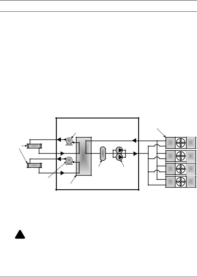
The Liebert XDC™ (X-treme Density Chiller) is self-contained refrigeration distribution unit designed to cool rooms with high heat producing equipment. There are two distinct circuits, each utilizing different refrigerants and mechanical parts. The R-134a circuit is the “pumped” circuit containing redundant circulating pumps, a brazed plate heat exchanger along with valves and piping. The R-407C circuit is the dual direct expansion circuit containing scroll compressors, expansion valves, brazed plate heat exchanger, and piping. Heat removal is accomplished by using condensers connected to the dual direct expansion circuit. Heat rejection is available in two options: an outdoor aircooled condenser and a water/glycol condenser. See Figure 1 below.
The Liebert XDC monitors room conditions and prevents coil condensation by maintaining the refrigerant being pumped to the cooling modules at a temperature above the room dew point. All functions, such as temperature control, switching pumps (if necessary), etc., are automatic.
The Liebert XDC’s minimum recommended operating load is 40% of system nominal capacity. For example, a Liebert XDC160 60Hz system’s minimum load would be 64kW. Loading below this value can unfavorably affect system operation. Consult factory for any loading below this recommendation.
See Table 26 for the Liebert XDC160 rated cooling capacity.
Figure 1 Liebert XDC components
Liebert XDC |
Liebert XD |
|
Cooling Modules |
Compressor |
|
Condenser |
|
Units |
|
Receiver |
Pumps |
Compressor |
|
Heat Exchanger |
|
1.2Equipment Inspection
When the unit is delivered, inspect all items for visible and concealed damage. Damage should be immediately reported to the carrier and a damage claim filed with a copy sent to Liebert or to your sales representative.
1.3Equipment Handling
! WARNING
Risk of unit falling over. Can cause death, injury and equipment damage.
The Liebert XDC is top-heavy. Use extreme caution and care when moving and installing this unit.
1
Product Description
1.3.1Handling With Skid
•Always keep the unit upright, indoors and protected from damage.
•If possible transport the unit using a forklift truck; otherwise use a crane with belts or cables. When using a crane, apply spreader bars to avoiding pressing on the top edges of the packaging.
•Personnel should be properly certified and trained to move and rig equipment.
•If using a forklift truck, make sure that the forks (if adjustable) are spread to the widest allowable distance that will fit under the skid.
•When moving the skidded unit with a forklift truck, do not lift the unit any higher than
6" (152mm) off the ground. If circumstances require the unit to be lifted higher than 6" (152mm), great care must be exercised, and all personnel not directly involved in raising the unit must be no closer than 20 feet (5m) from the lift point of the unit.
! CAUTION
Risk of structural interference. Can cause equipment or building damage.
While on the skid, the unit is too tall (83" [2108mm] overall height) to fit through a standard doorway. Any attempt to move the unit, while skidded, through a standard doorway will cause damage to the unit and to the building.
1.3.2Removal of Skid
For skid removal, Emerson Network Power recommends using pallet jack or similar operation. This is to ensure that both ends of the unit are firmly secure, and provides a good means of unit mobility.
Always keep the unit upright, indoors and protected from damage.
1.Remove the exterior packaging.
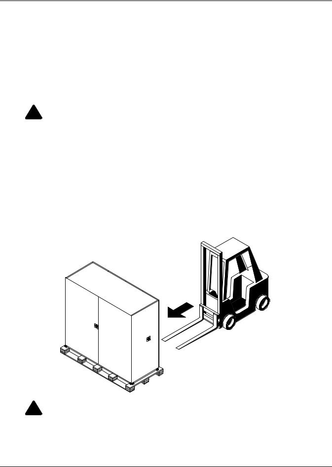
2.Align forklift with either the front or rear of the unit. Ensure the forks are locked at the widest position that will fit under pallet (see Figure 2).
Figure 2 Moving Liebert XDC with forklift
Spread forks as far apart as possible and drive forklift against the Liebert XDC
! CAUTION
Risk of unit damage. Ensure the forklift tines are level and not angled in an upward direction. Improper positioning may cause damage to the bottom of the unit. Ensure the forks are positioned in a manner as to have the Center of Gravity label, located on the unit, centered between the tines. Ensure the tines extend beyond the opposite side of the unit.
3. Drive the forklift forward, sliding the forks under the base of the unit (see Figure 2).
2
Product Description
4. Move the Liebert XDC to its installation location.
! WARNING
Risk of unit falling over. Can cause death, injury and equipment damage.
The Liebert XDC is top-heavy. Use extreme caution and care when moving and installing this unit.
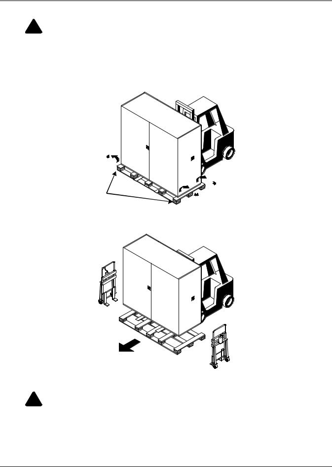
5.Remove all lag bolts from the four (4) corner tie-down brackets. Remove the tie-down brackets from the unit. (see Figure 3).
Figure 3 Remove tie-down brackets
Unscrew lag bolts and remove brackets to release the XDC from the pallet. There are four brackets, one bracket on each corner.
6. Lift the Liebert XDC about an inch and remove the shipping pallet.
Figure 4 Remove pallet, insert piano jacks
7.Place piano jacks at either end of the Liebert XDC and lower it until it is supported by the piano jacks. Secure the Liebert XDC to the jacks (see Figure 4 for arrangement).
! CAUTION
Risk of overtightening securing strips. Can cause damage to panels.
Place a protective material between the straps of the piano jacks and the unit. Ensure that the straps are not tightened to a point of damaging panels.
8.Back the forklift away from the Liebert XDC until the forks are no longer under the unit.
9.Using the piano jacks, maneuver the Liebert XDC into its installation position—this requires at least two people.
3
Product Description
1.3.3Removing Piano Jacks
Once the unit has been moved to the installation location, Emerson Network Power recommends using the following method to remove the piano jacks.
1.Lower the unit as far as the piano jacks will allow.
2.Undo all strapping holding the piano jacks to the unit.
3.Remove all cushioning material that might have been used to protect the unit panels from the strapping and/or the piano jacks.
4.Use a pry bar or similar device on one side of the unit, lift unit just enough to allow for the removal of the piano jack.
5.Repeat the previous step to remove the piano jack on the opposite side.
6.Remove the plastic bag.
1.4Mechanical Considerations
1.4.1Positioning the Liebert XDC
Install the Liebert XDC according to the site specific documentation and secure the unit to the floor.
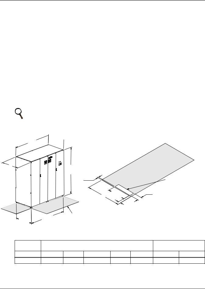
The Liebert XDC can be installed near a wall or another Liebert XDC. However, there must be at least 3 feet (92cm) clearance in front of the Liebert XDC as service access for components in the unit.
NOTE
During installation of the Liebert XDC, the top, bottom, front and left side of the unit must be accessible.
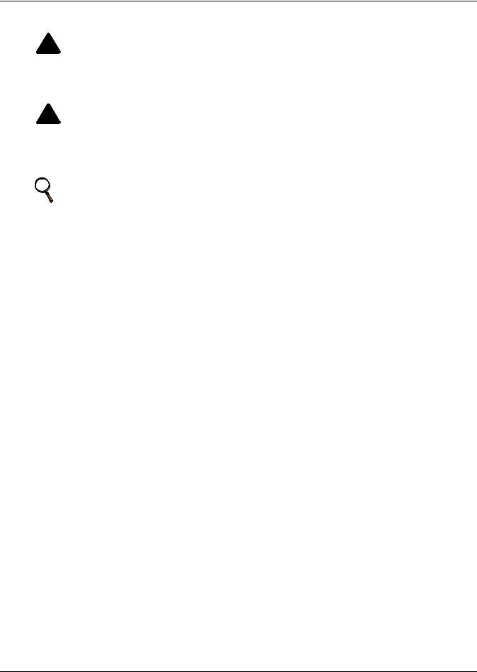
Figure 5 Dimensional data
 B
B
A Overall
Overall
C |
|
78" |
|
|
|
|
|
|
|
|
|
|
|
|
|
|
|
|
|
1981mm |
|
|
|
|
|
|
|
|
|
1" |
|
|
|
Recommended |
|
|
|
(25.4mm) |
|
|
|
Minimum Hot Gas |
||
|
|
|
|
17" |
|
|
Supply & Liquid Return |
|
|
|
|
|
|
5" |
Piping Opening |
||
|
|
|
D |
(432mm) |
|
|
|
|
|
|
|
(127mm) |
|
||||
|
|
|
|
|
|
|||
|
|
|
|
2" |
|
|
|
|
|
|
|
|
(51mm) |
Floor Cutout Dimensions |
|||
D |
E |
Shaded areas indicate a |
|
|
|
|
|
|
Unit |
Unit Base |
recommended clearance |
|
|
|
DPN000768 |
||
Base |
|
of 34" (864mm) for |
|
|
|
Pg. 2, Rev. 6 |
||
Unit Dimensional Data |
|
|
|
|||||
component access. |
|
|
|
|
|
|||
Table 1 |
Liebert XDC dimensions, weight |
|
|
|
|
|
||
Air-Cooled |
|
|
|
|
|
|
|
|
Model |
|
Dimensional Data, inches (mm) |
|
|
Shipping Weight, lb (kg) |
|||
50/60Hz |
A |
B * |
C |
D |
E |
|
Domestic |
Export |
XDC160 |
74 (1880) |
34 (864) |
33-1/8 (841) |
33 (838) |
72 (1829) |
1945 (882) |
2093 (949) |
|
* Dimension does not include the bezel of the disconnect switch.
4
Product Description
Figure 6 Piping locations
** To first cooling module |
|
|
or bypass flow controller |
Install replaceable filter dryer |
|
|
|
|
|
|
assembly in liquid supply line G |
|
|
* Orientation determined |
F - Return From Cooling Units |
by installer. |
|
|
||
47" |
|
G - Supply to Cooling Units |
44" |
|
|
(1193.8mm) |
|
|
(1117.6mm) |
|
|
6" (152mm) 


23" 
 (584.2mm)
Dimensions are approximate and subject to change without notice.
A - Hot Gas |
|
|
|
|
|
|
|
|
|
|
|
|
|
B - Liquid |
|
|
|
|
|
|
|
|
|
|
|
|
|
||
Refrigerant Lines |
|
|||||||||||||
|
Refrigerant Lines |
|||||||||||||
* Allow 8" (204mm) of clearance for filter replacement |
|
|||||||||||||
|
|
|||||||||||||
** To ensure all refrigerant flow is filtered, install the filter dryer assembly |
|
DPN000768 |
|||||||||||
between the discharge line of the Liebert XDC and the first bypass |
|
||||||||||||
flow controller or the first cooling module. |
|
|
|
|
|
Pg. 3, Rev. 6 |
|||||||
|
Table 2 |
Liebert XDC piping connection sizes |
|
|
|
|
|
|
|
||||
|
|
|
|
|
|
|
|
|
|
|
|||
|
Air-Cooled Model |
|
Piping Outlet Connection Sizes, OD Cu, inches |
|
|
|
|||||||
|
|
|
|
|
|
|
|
|
|
|
|
|
|
|
50/60Hz |
A |
B |
|
C |
D |
E |
|
F |
|
G |
|
|
|
|
|
|
|
|
|
|
|
|
|
|
|
|
|
XDC160 |
1-3/8 |
7/8 |
|
- |
- |
- |
|
2-1/8 |
|
1-1/8 |
|
|
|
|
|
|
|
|
|
|
|
|
|
|
|
|
5
Product Description
1.4.2Placing the Liebert XDC on a Floor Stand
! WARNING
Risk of top-heavy unit falling over. Improper handling can cause equipment damage, injury or death.
Read all of the following instructions before attempting to move, lift, remove packaging from or preparing unit for installation.
! CAUTION
Only properly trained and qualified personnel wearing appropriate safety headgear, gloves, shoes and glasses should attempt to move, lift, remove packaging from or prepare unit for installation.
The water/glycol floor stand can be located beneath the Liebert XDC unit or can be installed nearby.
NOTE
Consult the factory if the Liebert XDC is not installed on the water/glycol condenser floor
stand to prevent exceeding maximum the piping distances.
Refer to the floor stand installation sheet shipped inside the water regulating valve package.
1.Move the floor stand assembly to its installation area and uncrate the unit.
2.Position the floor stand in its final location.
3.Insert leveler pads into each floor stand leg.
4.Level the top of the floor stand to the specified height with the flanged adjusting nut.
5.Tighten jam nuts on all legs against flanged adjusting nuts.
6.Using an appropriate lifting device or method, raise the Liebert XDC and move it above the floor stand.
7.Align the welded tabs on top of the floor stand with the inside of the unit frame base (see Detail A in Figure 7).
8.Maintaining the alignment of the Liebert XDC and the floor stand, lower the Liebert XDC onto the floor stand.
9.Connect the hot gas refrigerant lines from the Liebert XDC to the floor stand with 1-3/8" tubing (see Figures 7 and 8).
10.Connect the liquid refrigerant lines as shown from the Liebert XDC unit to the floor stand with 7/8" tubing (see Figures 7 and 8).
11.Connect the water lines as shown with the provided valving (see Figures 7 and 8).
12.Connect capillary lines from each water regulating valve to condensers in the floor stand (see
Figures 7 and 8).
Capillary length is limited to 48" (1219mm).
13.Check the pipes for leaks and evacuate air from all pipes.
14.Insulate all water/glycol lines.
15.Charge each condenser loop with R-407C (see Table 18).
6

Product Description
Figure 7 Water/glycol Liebert XDC on a floor stand—positioning and piping connections
|
44" |
47" |
(1118mm) |
(1194mm)
6"
(153mm)
 23" (584mm)
C - Hot Gas
Refrigerant Lines
D - Liquid
Refrigerant Lines
E - Threaded


Female
Connections
Customer 
Water
Return
A - Return from
Cooling Units
B - Supply to
Cooling Units
Welded Tab
A
DETAIL A
Customer
Water

 Supply
 F - Cup Fitting
Capillary Lines are 48" (1220mm) Limit Valve Distance from Condensers
Customer Provided Piping |
DPN001419 |
|
Pg. 1, Rev. 1 |
Table 3 |
Liebert XDC water/glycol piping connection Sizes |
||||||
Model |
Piping Outlet Connection Sizes, OD Cu, inches |
|
|||||
|
|
|
|
|
|
|
|
50/60Hz |
A |
B |
C |
D |
E* |
F** |
|
|
|
|
|
|
|
|
|
XDC160 |
2-1/8 |
1-1/8 |
1-3/8 |
7/8 |
2-1/2 |
2-1/8 or 2-5/8 |
|
|
|
|
|
|
|
|
|
*Threaded female connection
**2-1/8" for 1" WRV, 2-5/8" for 1-1/4" WRV
7
Product Description
Figure 8 Piping locations—floor stand and valve assembly
72" |
33" |
(838mm) |
(1828mm)
24" Nominal |
(609mm) |
Water-Regulating
Valve Assembly
Capillary Tubes
TOP VIEW OF FLOOR STAND |
|
Shaded areas indicate a recommended |
|
Hot Gas 1 |
Liquid 1 |
clearance of 36" (915mm) for component |
|
access and water/glycol piping. |
|||
Hot Gas 2 |
Liquid 2 |
33" (838mm) |
|
Outlet |
|
|
|
|
|
|
20-1/4" |
|
|
|
(514mm) |
|
|
|
10-1/2" |
|
|
|
(267mm) |
|
|
|
6-1/2" |
|
|
(165mm) |
|
|
|
12-5/16" |
2-1/4" - 5-1/4" |
Circuit 1 |
Circuit 2 |
(313mm) |
(57 - 133 mm) |
26-15/16" (684mm) |
|
||
|
|
DPN001419 |
|
Inlet |
|
LEFT SIDE OF CABINET |
|
FLOOR STAND CONNECTIONS |
|
Pg. 2, Rev. 1 |
|
|
|
||
8
Product Description
1.4.3Positioning the Liebert XDC with Floor Stand
Install the Liebert XDC according to the site-specific documentation and secure the unit to the floor.
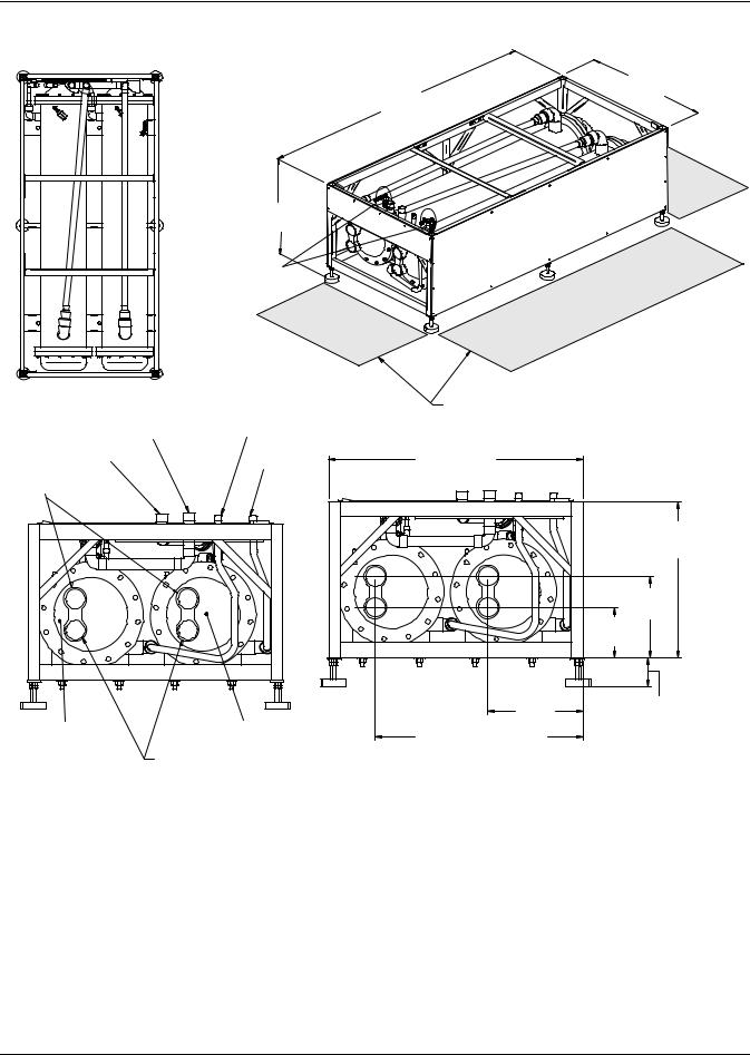
The Liebert XDC can be installed near a wall or another Liebert XDC. There must be at least 3 feet (914mm) clearance in front of the Liebert XDC for service access. When the Liebert XDC is combined with the optional water/glycol floor stand, Liebert recommends leaving 3 feet (914mm) of clearance on the left side of the unit.
A Liebert XDC on a floor stand is 102 inches (2591 mm) high (see Figure 9). The unit can be raised or lowered 1.5 inches (38.1 mm) with the leveling feet.
Figure 9 Dimensions and clearances for Liebert XDC on floor stand
78"
(1981mm)
102"
(2591mm)
 24" Nominal
610 mm
Shaded areas indicate a recommended clearance of 36" (914mm) for component access and water/glycol piping.
9
Product Description
1.5High Voltage Connections
Make sure the actual supply voltage and frequency correspond to the voltage and frequency indicated on the Liebert XDC’s rating plate.
Connect cables for high voltage supply to the electrical box in the Liebert XDC according to Figures 5, 11 and 12 and make sure that the phases are correctly connected.
! WARNING
Risk of electric shock. Can cause death or injury.
Disconnect all local and electric remote power supplies before working within.
! CAUTION
Risk of sharp edges and heavy parts. May cause personal injury or equipment damage. Wear gloves to prevent injury to hands.
Damage to wiring or components can make unit unsafe to operate.
Use caution when installing wiring to prevent damage to factory wiring. Install protective bushings in wiring knockouts as required
Do not disturb factory wiring or route field-installed wiring over electrical terminals. Use NEC Class 1 wiring for all hazardous voltage electrical power supplies.
Check and retighten all wiring connections before starting the unit.
NOTE
Before beginning to install the Liebert XDC, read all instructions, verify that all the parts are included and check the nameplate to be sure the Liebert XDC voltage matches available utility power.
Follow all local codes.
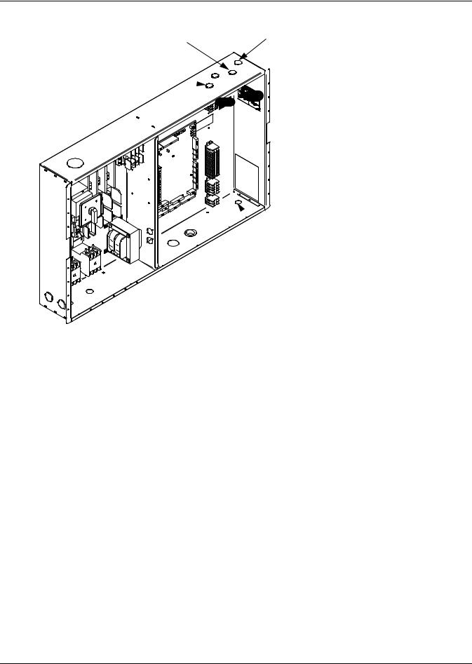
1.5.1Connecting High-Voltage Cables
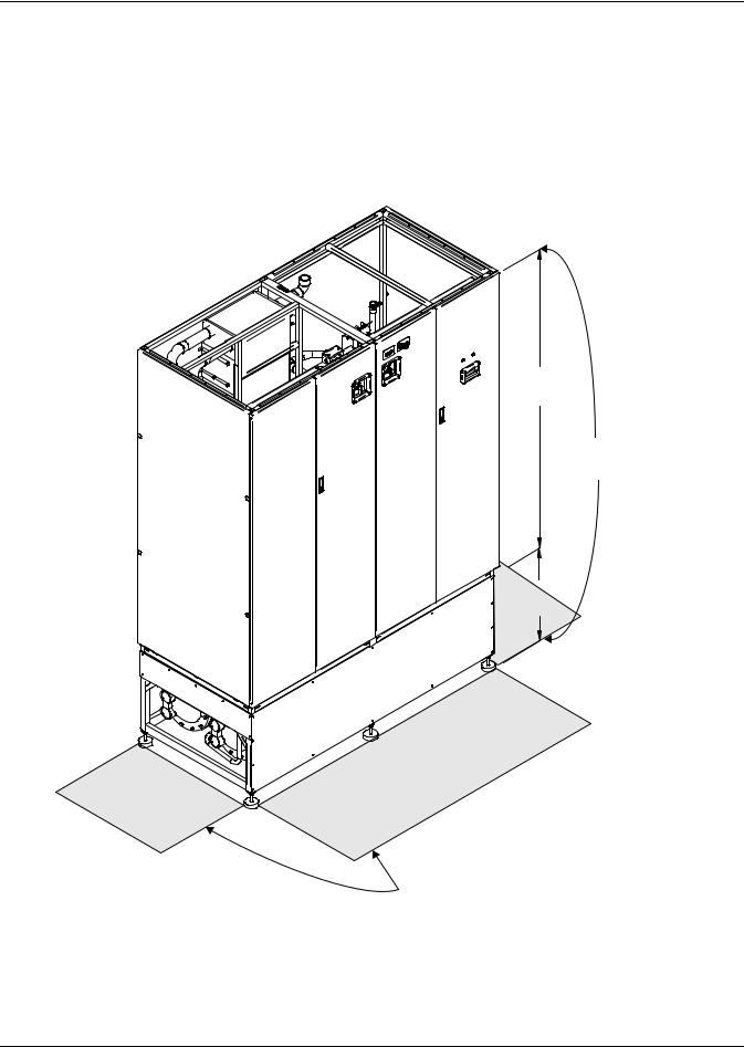
1.Turn the Liebert XDC’s primary disconnect switch to the Off position (see Figure 10). Open the front doors and push down on the enclosure cover latch to open the hazardous voltage enclosure cover.
Figure 10 Front view of Liebert XDC and electrical enclosures
Primary Disconnect |
Secondary Disconnect |
Switch |
Switch |
|
Status Lamps |
|
User Interface |
Enclosure Cover
Latch
Enclosure Cover
Latches
Hazardous Voltage |
Hazardous Voltage |
Enclosure Cover |
Enclosure Cover |
PRIMARY |
SECONDARY |
ELECTRICAL ENCLOSURE |
ELECTRICAL ENCLOSURE |
COMPRESSOR SECTION |
PUMP SECTION |
10

Product Description
2.Determine which knockouts in the electrical enclosure will be used and remove them (see
Figure 11).
Figure 11 Electrical enclosure knockout locations for field wiring
Knockout for
Input Power
Enclosure Cover
Not Shown for Clarity
3.Route the input hazardous voltage electrical power wiring through the top right knockout on the primary electrical enclosure (see Figure 11) to the disconnect switch L1, L2 and L3 (see Figure 12). Observe proper phasing.
4.Connect the ground wire to the ground lug (see Figures 12 and 14 for 60Hz models and Figures 13 and 15 for 50Hz models).
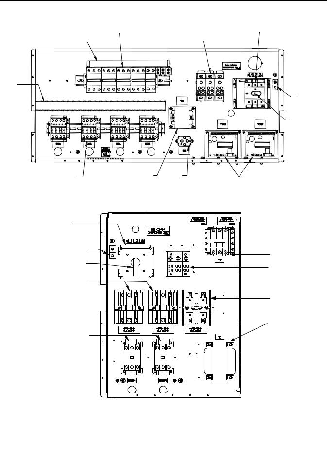
Figure 12 60Hz models, high voltage connections—primary disconnect switch
Transformer Fuse Block |
Customer Power Connection |
||
Compressor Fuse Blocks |
Primary Power Block |
|
|
|
|||
|
|
|
Ground |
|
|
|
|
Lug |
|
|
|
|
Primary |
|
|
|
|
Disconnect |
|
|
|
|
Switch |
|
Compressor Contactors |
Transformer 3 |
Relay |
Electronic Hot Gas |
|
Bypass Controllers |
||||
|
|
|
11
Product Description
Figure 13 50Hz models high voltage connections—primary disconnect switch
Compressor |
|
|
|
Customer |
|||
Circuit Breakers |
|
|
|
Power |
|
||
|
|
|
|
||||
|
|
||||||
Busbar |
|
|
|
Primary Power Block |
|
Connection |
|
|
|
||||||
|
|
|
|||||
Wire
Raceway
Ground
Lug
Primary
Disconnect
Switch
Compressor |
Transformer 3 |
Relay |
Electronic Hot Gas |
Contactors |
|
|
Bypass Controllers |
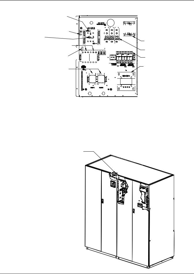
Figure 14 60Hz models high voltage connections—secondary disconnect switch
Power Connection |
|
|
From Primary |
|
|
Power Block |
|
|
Ground Lug |
Transformer 2 |
|
Secondary Disconnect |
||
Secondary |
||
Switch |
||
Power Block |
||
Pump Fuse |
||
|
||
Blocks |
Transformer |
|
|
||
|
Fuse Block |
|
|
Transformer 1 |
|
Pump Contactors |
|
12
Product Description
Figure 15 50Hz models high voltage connections—secondary disconnect switch
|
Power Connection |
|
|
|
From Primary |
|
|
|
Power Block |
|
|
|
Ground Lug |
|
|
Secondary |
|
||
Disconnect |
Transformer 2 |
||
Switch |
Pump Circuit |
||
|
|||
|
Power Block |
||
|
Breakers |
||
|
Busbar |
Fuse Blocks |
|
Pump Contactors |
Transformer 1 |
||
|
|||
1.6Extra Low Voltage Connections
Extra Low Voltage (ELV) power output is 30V and 100VA or less.
1.Turn off all unit power before connecting cables or wires. Failure to do so may damage this equipment.
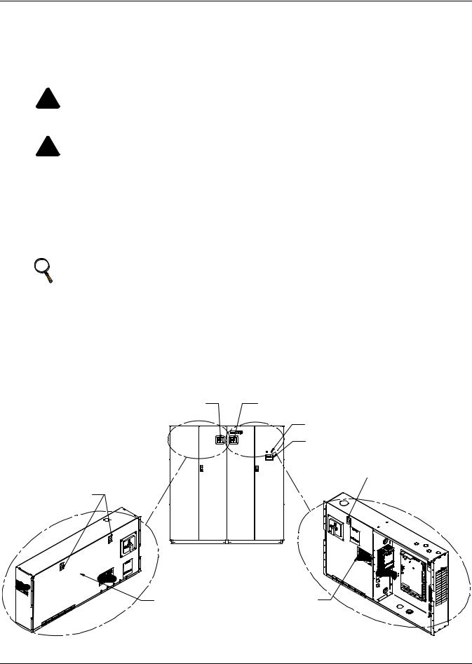
2.Route low voltage electrical connections through the appropriate knockouts as shown in
Figure 17.
3.User interface and temperature/humidity sensor wire is NEC Class 2. All electrical installation must comply with all national, state and local requirements.
Figure 16 Liebert XDC heat rejection connection points
HEAT REJECTION CONNECTION
Field-supplied 24V. Class 1 wiring
to interlock heat rejection from pigtails: 70A and 71A - Compressor 1 circuit 70B and 71B - Compressor 2 circuit
Electrical handy box,  factory-installed with cover
13
Product Description
Figure 17 Electrical enclosure knockout locations for Extra Low Voltage connections
User Interface
(Wall Box) Wiring
Temperature/Humidity
Sensor Wiring 
Liebert XD Module Condensate Connections (optional; depends on features

 supplied with Liebert XD Module)
 Alternate Knockout
for Temperature/Humidity
Sensor Wiring
Enclosure Cover Not Shown for Clarity
Field Connections—All Units
•Connect the control display panel cable to terminal block TB3 terminals 1 through 4 on the Liebert XDC control board as shown (refer to Figure 18). The display panel must always be installed in the conditioned space. The display panel may be mounted on the Liebert XDC’s front right door if the Liebert XDC is located in the area that it conditions.
•Place the sensor in the higher-temperature portion of the cold aisle where the Liebert XD modules
are located. Alternatively, it may be placed on the return air side of the primary air mover (e.g., Liebert DS™) in the room if it represents the conditions where all the Liebert XD cooling modules are located. Do not install the sensor where ambient air might cause false readings, for example, near unsealed doors, windows and similar areas.
Field Connections—Optional for All Units
•Connect optional field wiring from remote devices to Remote Alarm Device, Common Alarm Output, IGM and Remote Shutdown, if applicable. See terminal strip descriptions in Figure 18.
Field Connections—Air-Cooled Units only
Connect field wiring to heat rejection connection terminals on the handy box as shown in Figure 16.
14
Loading...