


Emerson Fisher 249, Fisher 249P, Fisher 249VS, Fisher 249W, Fisher 249BP Instruction Manual
...Instruction Manual Supplement |
249 Sensors |
D103066X012 |
March 2014 |
|
|
Simulation of Process Conditions for Calibration of Fisherr Level Controllers and Transmitters—Supplement to 249 Sensor Instruction Manuals
Displacer / torque tube sensors are transducers that convert a buoyancy change into a shaft rotation. The change in buoyancy is proportional to the volume of fluid displaced, and the density of the fluid. The change in rotation is proportional to the change in buoyancy, the moment arm of the displacer about the torque tube, and the torque rate. The torque rate itself is a function of the torque tube material, the temperature of the material, the wall thickness, and the length. If the density of the process fluid, process temperature, and torque tube material of the sensor are known, simulation of process conditions may be accomplished by one of the following means(1):
1. Weight or Force Method:
The interface application is the most general case. The level application can be considered an interface with the upper fluid SG = 0, and the density application can be considered as a variable SG application with the interface at the top of the displacer. The buoyancy for a given interface level on the displacer is given by:
FB = ρw* VD * [ SGU)Hdisp * (SGL - SGU ) ] |
(1) |
Figure 1. Cutaway View of Fisher 249 Displacer |
|
||
|
Sensor |
Where: |
|
|
FB |
= |
buoyant force |
ρw |
= density of water at 4_C, 1 |
|
|
|
atmosphere = 1.0000 Kg/liter |
|
|
(0.03613 lb/in3) |
VD |
= |
displacer volume |
Hdisp |
= height of interface on displacer, |
|
|
|
normalized to displacer length |
SGU |
= specific gravity of upper fluid |
|
|
|
(0.0 for Level) |
SGL |
= specific gravity of lower fluid |
|
DRIVER ROD
 TORQUE TUBE

 SUSPENSION ROD
 LIQUID DISPLACER
W2141-1
1. Note that this document does not consider the effects of the thermal expansion of the moment arm, or the thermal expansion of displacer volume.
www.Fisher.com
249 Sensors |
|
Instruction Manual Supplement |
March 2014 |
|
D103066X012 |
|
|
|
|
|
|
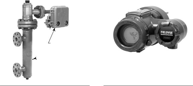
Figure 2. Fisher 2500 or 2503 Level Controller |
|
Figure 3. FIELDVUE™ DLC3010 Digital Level |
Transmitter on Caged 249 Sensor |
|
Controller |
2500 OR 2503 CONTROLLER/ TRANSMITTER
 249 SENSOR
W7977
W8334
For the density application, Hdisp = 1.0, SGu = lowest expected density, and SGL becomes the independent variable, the actual process density.
The net load on the driver rod is then computed from the equation:
(2)
Wnet = WD - FB
= net load on driver rod = weight of displacer
To simplify equations in the following discussion, let us define a few intermediate terms:
The minimum buoyancy, developed when the interface level is at the bottom of the displacer, is given by:
(3)
FBmin = ρw * VD * SGU
The change in buoyant force as the normalized interface level rises on the displacer is:
(4)
FB = ρw * VD * (SGL - SGU) * Hdisp
The maximum change in buoyancy, developed when the interface level is at the top of the displacer is:
(5)
(ΔFB)max = ρw * VD * (SGL - SGU)
2

Instruction Manual Supplement |
249 Sensors |
D103066X012 |
March 2014 |
|
|
Temperature Effect
As process temperature increases, the torque rate decreases due to the change in modulus of rigidity. This effect can be represented by normalizing the modulus vs. temperature curve for a given material to the room temperature value, and using it as a scale factor on the torque rate. See figure 4 and table 1 or 2.
Because we can simulate the rotation of a more compliant torque tube by increasing the load, the weight value may be divided by the same scale factor to simulate the process condition:
Wnet_test
Where:
Wnet_test
(6)
=WD - FB
Gnorm
=net load adjusted to simulate process temperature effect
Gnorm |
= normalized modulus of torque |
|
tube material, a function of |
|
temperature. |
Displacer Rise Effect
Note that equation 6 simulates the process level on the displacer. The actual level in the cage or vessel will be different, due to the rise of the displacer as the torque tube load is decreased by the increasing buoyancy.
On a 14 inch displacer, or on a 249VS with a long driver rod, the displacer rise can become a significant fraction of the span. If the torque tube rate and driver rod length are known, change in rotation can be computed by dividing the torque change by the rate.
(7)
Angle = |
FB |
* Driver |
* |
( π /180_ ) |
|
Ramb |
* Gnorm |
||||
|
|
|
|||
Where: |
|
|
|
|
|
Angle |
= resulting change in torque tube |
||||
|
angle in radians |
|
|||
Driver |
= driver rod length |
|
|||
Ramb |
= Torque rate (torque per |
||||
|
_rotation) at ambient |
||||
temperature
3

249 Sensors |
Instruction Manual Supplement |
March 2014 |
D103066X012 |
|
|
Figure 4. “Gnorm”: Theoretical Temperature Effect on Torque Rate for Most Commonly Used Materials
TORQUE RATE REDUCTION
(NORMALIZED MODULUS OF RIGIDITY)
Gnorm
1.00 |
|
|
|
|
|
|
|
|
|
|
|
|
|
|
|
|
|
|
|
|
0.98 |
|
|
|
|
|
|
|
|
|
|
|
|
|
|
|
|
|
|
|
|
0.96 |
|
|
|
|
|
|
|
|
|
|
|
|
|
|
|
|
|
|
|
|
0.94 |
|
|
|
|
|
|
|
|
|
|
|
|
|
|
|
|
|
|
|
|
0.92 |
|
|
|
|
|
|
|
|
|
|
|
|
|
|
|
|
|
|
|
N05500 |
|
|
|
|
|
|
|
|
|
|
|
|
|
|
|
|
|
|
|
|
N06600 |
0.90 |
|
|
|
|
|
|
|
|
|
|
|
|
|
|
|
|
|
|
|
|
|
|
|
|
|
|
|
|
|
|
|
|
|
|
|
|
|
|
|
|
N10276 |
0.88 |
|
|
|
|
|
|
|
|
|
|
|
|
|
|
|
|
|
|
|
|
0.86 |
|
|
|
|
|
|
|
|
|
|
|
|
|
|
|
|
|
|
|
|
0.84 |
|
|
|
|
|
|
|
|
|
|
|
|
|
|
|
|
|
|
|
|
0.82 |
|
|
|
|
|
|
|
|
|
|
|
|
|
|
|
|
|
|
|
|
0.80 |
|
|
|
|
|
|
|
|
|
|
|
|
|
|
|
|
|
|
|
S31600 |
|
|
|
|
|
|
|
|
|
|
|
|
|
|
|
|
|
|
|
|
|
20 |
40 |
60 |
80 |
100 |
120 |
140 |
160 |
180 |
200 |
220 |
240 |
260 |
280 |
300 |
320 |
340 |
360 |
380 |
400 |
420 |
TEMPERATURE (_C)
TORQUE RATE REDUCTION
(NORMALIZED MODULUS OF RIGIDITY)
Gnorm
1.00 |
|
|
|
|
|
|
|
|
|
|
|
|
|
|
|
0.98 |
|
|
|
|
|
|
|
|
|
|
|
|
|
|
|
0.96 |
|
|
|
|
|
|
|
|
|
|
|
|
|
|
|
0.94 |
|
|
|
|
|
|
|
|
|
|
|
|
|
|
|
0.92 |
|
|
|
|
|
|
|
|
|
|
|
|
|
|
N05500 |
|
|
|
|
|
|
|
|
|
|
|
|
|
|
|
|
|
|
|
|
|
|
|
|
|
|
|
|
|
|
|
N06600 |
0.90 |
|
|
|
|
|
|
|
|
|
|
|
|
|
|
|
|
|
|
|
|
|
|
|
|
|
|
|
|
|
|
N10276 |
0.88 |
|
|
|
|
|
|
|
|
|
|
|
|
|
|
|
0.86 |
|
|
|
|
|
|
|
|
|
|
|
|
|
|
|
0.84 |
|
|
|
|
|
|
|
|
|
|
|
|
|
|
|
0.82 |
|
|
|
|
|
|
|
|
|
|
|
|
|
|
|
0.80 |
|
|
|
|
|
|
|
|
|
|
|
|
|
|
S31600 |
50 |
100 |
150 |
200 |
250 |
300 |
350 |
400 |
450 |
500 |
550 |
600 |
650 |
700 |
750 |
800 |
TEMPERATURE (_F)
NOTE: THIS CHART DEPICTS THE REVERSIBLE CHANGE ONLY. THE IRREVERSIBLE DRIFT IS A FUNCTION OF THE NET LOAD, THE ALLOY, AND THE LEVEL OF STRESS EQUALIZATION ACHIEVED IN MANUFACTURING. (THE IRREVERSIBLE EFFECT CAN ONLY BE COMPENSATED BY PERIODIC ZERO TRIM.) N05500 IS AN APPROPRIATE SPRING MATERIAL FOR TEMPERATURES BELOW AMBIENT AND UP TO 232_C (450_F). ABOVE 260_C (500_F), THE INDUSTRY DOES NOT RECOMMEND USING IT AS A SPRING MATERIAL. N06600 IS CONSIDERED ACCEPTABLE TO APPROXIMATELY 399_C (750_F) WITH PROPER STRESS EQUALIZATION.
4
 Loading...