


FTA1100-J
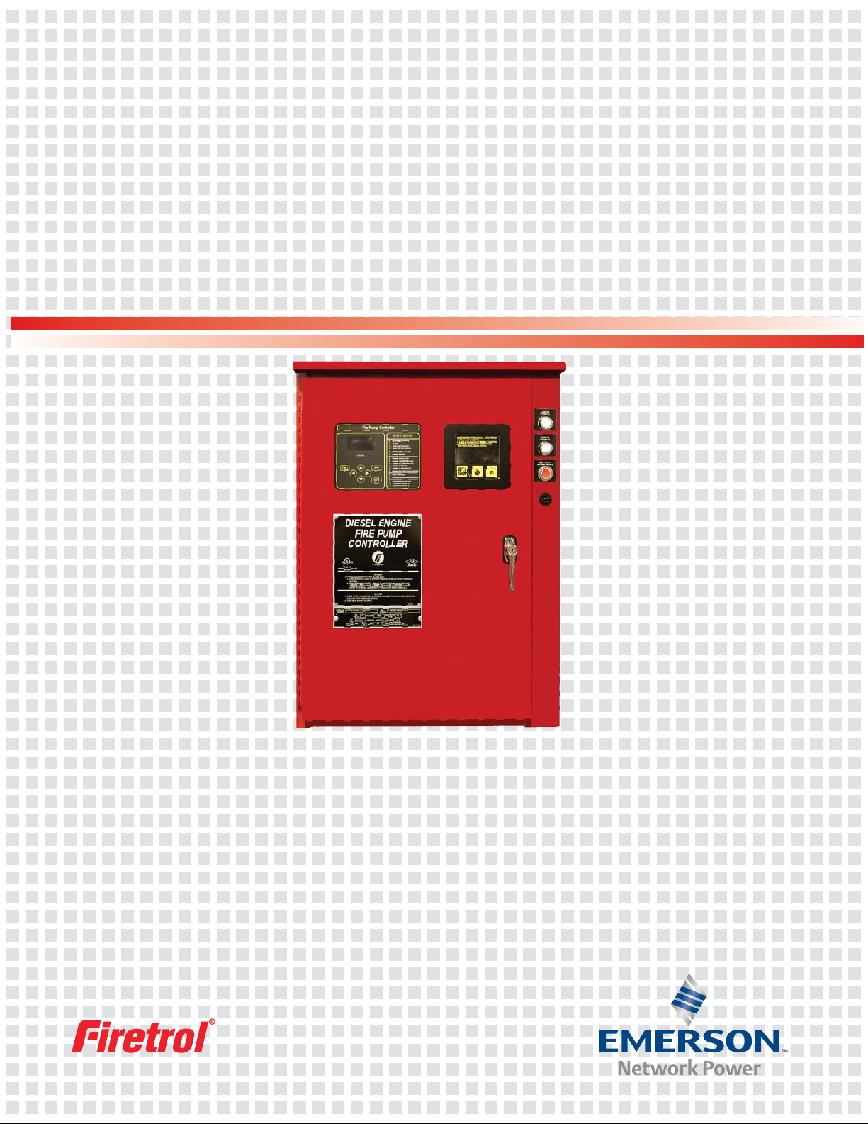
Diesel Engine Fire Pump Controllers
Compatible with mechanical and
electronic engine types.
Firetrol
®
combined automatic and manual Mark
IIXG based diesel engine fi re pump controllers
are intended for starting and monitoring fi re
pump diesel engines. The controller monitors,
displays and records fi re pump system informa-
tion. Diesel engine fi re pump controllers are
available in 12 or 24 volts, work with lead acid
or Nickel-Cadmium batteries and are designed
to operate seamlessly with either mechanical
or electronic engine types.
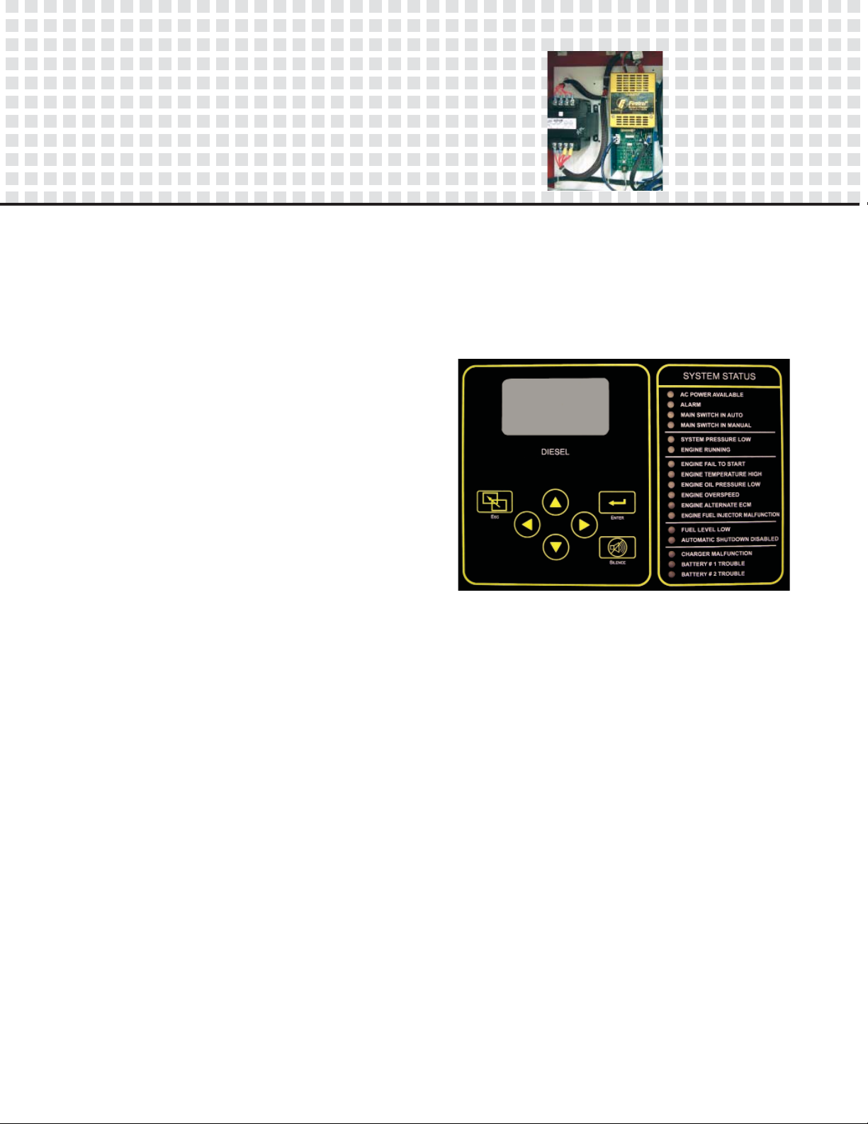
Operator Interface
The fi re pump controllers feature an opera-
tor interface with user keypad. The interface
monitors and displays motor operating condi-
tions, including all alarms, events, and pressure
conditions. All alarms, events, and pressure
conditions are displayed with a time and date
stamp. The display is a 128x64 Backlit LCD ca-
pable of customized graphics and Cyrillic type
character display. The display and interface are
NEMA rated for Type 2, 3R, 4, 4X, and 12 pro-
tection and is fully accessible without opening
the controller door. The user interface utilizes
multiple levels of password protection for sys-
tem security. A minimum of 3 password levels
are provided.
Approvals
Firetrol fi re pump controllers are listed by Un-
derwriters’ Laboratories, Inc., in accordance
with UL218, Standard for Fire Pump Controllers,
CSA, Standard for Industrial Control Equipment,
and approved by Factory Mutual. They are built
to meet or exceed the requirements of the ap-
proving authorities as well as NEMA and
Firetrol designed 4-stage
battery charger.
Battery Chargers
The controllers are supplied with two fully au-
tomatic, 200 amp hour, 4 step battery chargers.
The chargers feature Switching Technology and
10Adc Pulse-Width Modulated Output Current.
The 4 step charging cycle is as follows:
Step 1 - Qualifi cation Stage
During this stage, the battery charger
checks the batteries to insure they can
accept a fast charge. It also checks
for missing or defective batteries. If
a missing or defective battery is de-
tected, a fault will be given.
Step 2 - Fast Charge Stage
Charges the batteries until they reach
peak voltage.
Step 3 - Bulk Charge Stage
Charges the batteries at a constant
potential of peak voltage until current
reaches 500mA.
Step 4 - Float Charge Stage
Trickle charges the batteries to main-
tain peak potential.
 Loading...