


 Loading...
PROPANE/LP GAS LIGHT HEATER
OWNER’S MANUAL
Models
TD100, TD102, TD104
AND TD110
Adjustable Temperature
Settings:
Low - 20,000 Btu
High - 36,500 Btu
 WARNING: For
Outdoor Use Only
 WARNING: Read and understand this manual before assembling, starting, or servicing heater. Improper use of heater can cause serious injury, property damage, or death. Keep this manual for future reference.
INSTALLER: Leave this manual with the appliance. CONSUMER: Retain this manual for future reference.
FOR YOUR SAFETY
Do not store or use gasoline or other flammable vapors and liquids in the vicinity of this or any other appliance.
FOR YOUR SAFETY If you smell gas:
1.Shut off gas to the appliance.
2.Extinguish any open flame.
3.If odor continues, immediately call your gas supplier.
Fill In For Your Records
Model No. _____________________
(Located on side panel)
Serial No._____________________
(Located on side panel)
Date of Purchase_______________
For more information, visit www.desatech.com
Table of Contents
Safety Information................................................ |
2 |
Wiring Diagram.................................................... |
9 |
Product Identification............................................ |
4 |
Illustrated Parts Breakdown and Parts List........ |
10 |
Unpacking Heater................................................ |
4 |
Troubleshooting................................................. |
14 |
Assembly.............................................................. |
5 |
Replacement Parts............................................. |
15 |
Operation............................................................. |
7 |
Technical Service............................................... |
15 |
Storage................................................................. |
8 |
Accessory........................................................... |
15 |
Maintenance......................................................... |
9 |
Warranty Information.......................................... |
16 |
Specifications....................................................... |
9 |
|
|
Safety Information
 WARNING: This product containsand/orgenerateschemicals knowntothestateofCaliforniato cause cancer or birth defects, or other reproductive harm.
 WARNING: Fire, burn, inhalation, and explosion hazard. Keep solid combustibles, such as building materials, wood, vinyl siding,paperorcardboard,asafe distance away from the heater as recommended by the instructions. Never use the heater in spaces which do or may contain volatileorairbornecombustibles, orproductssuchasgasoline,solvents,paintthinner,dustparticles or unknown chemicals.
 WARNING: Improper installation, adjustment, alteration, serviceormaintenancecancause injury,propertydamage,ordeath. Read the installation, operating, and maintenance instructions thoroughly before installing or servicing this equipment.
 WARNING: For use only outdoors in a well ventilated space.
Do not use heater indoors or in a building or garage or any unventilated or enclosed areas.
The heater is designed for use as an infrared patio heater in accordance with the applicable requirements CSA 5.90 U.S Infrared Patio Heaters, CAN 1-2.23 Portable Infra Red Heaters for Canada. Other standards govern the
use of fuel gases and heating products for specific uses. Your local authority can advise you about these. The primary purpose of outdoor patio heaters is to provide heating of residential and nonresidential spaces. Properly used, the heater provides safe economical heating.
We cannot foresee every use which may be made of our heaters. Check with your local fire safety authority if you have questions about heater use.
Carbon Monoxide Poisoning: Some people are more affected by carbon monoxide than others. Early signs of carbon monoxide poisoning resemble the flu, with headaches, dizziness and/or nausea. If you have these signs, the heater may not be working properly. Get fresh air at once! Have heater serviced.
Propane/LP Gas: Propane/LP gas is odorless. An odor-making agent is added to propane/LP gas. The odor helps you detect a propane/LP gas leak. However, the odor added to propane/LP gas may fade. Propane/LP gas may be present even though no odor exists.
Make certain you read and understand all warnings. Keep this manual for reference. It is your guide to safe and proper operation of this heater.
1.Install and use heater with care. Follow all local ordinances and codes. In the absence of local ordinances and codes, refer to the Standard for Storage and Handling of Liquefied Petroleum Gas, ANSI/NFPA 58, CSA/-B149 Installation CODE. This instructs on the safe storage and handling of propane/LP gases.
2.Use only propane/LP gas set up for vapor withdrawal in a 20 lb. cylinder. Cylinder must be constructed and marked in accordance with specifications for propane/LP cylinders of the U.S. Department of Transportation (DOT) or the National Standard of Canada CAN/CSA-B339. The cylinder must be provided with a shutoff valve terminating in a propane/LP supply cylinder valve outlet. The valve must have external threads and marked “Use with Type 1” and
|
www.desatech.com |
118994-01G |
SAFETY INFORMATION
Continued
a safety relief device having a direct communication with the vapor space of the cylinder. The cylinder used must include a collar to protect the cylinder valve. The cylinder must be equipped with a listed over filling protection device.
3.Keep appliance area clear and free from combustible materials, gasoline, paint thinner and other flammable vapors and liquids. Dust is combustible. Do not use heater in areas with high dust content.
4.Minimum heater clearances from combustibles: Back 4" (10.2 cm), Sides 12" (30.5 cm); Front 42" (1.07 m); Top 16" (40.6 cm) (see Figure 1).
5.Before each use, check heater for leaks. Never use an open flame to check for a leak. Apply a mixture of liquid soap and water to all joints. Bubbles forming show a leak. Correct all leaks at once.
6.Keep propane/LP cylinder below 100° F (38° C).
7.Use only the hose and factory preset regulator provided with the heater. Do not adjust regulator as gas leaks may occur.
8.Locate hose properly, keeping it out of pathways where people may trip over it or in areas where the hose may be subjected to accidental damage.
9.Check hose before each use of heater. Disconnect hose with 9/16" wrench. Check for tears and abrasions in hose and on regulator. If highly worn or cut, replace with hose specified by manufacturer before using heater.
10.Do not alter heater. Keep heater in its original state. Do not use heater if altered.
11.Locate heater on stable and level surface.
12.Do not operate heater while sleeping or leave heater unattended.
13.Never move, handle or service a hot or operating heater. Severe burns may result. You must wait 20 minutes after turning heater off.
14.To prevent injury, wear gloves when handling heater.
15.Turn off heater valve and gas supply to heater when not in use.
16.Use only original replacement parts. This heater must use design-specific parts. Do not substitute or use generic parts. Improper replacement parts could cause serious or fatal injuries.
17.Certain materials or items, when stored in front of heater, will be subjected to radiant heat and could be seriously damaged.
18.Shut heater off immediately if flashback occurs (flame inside burner tube). Have heater serviced.
19.Never attempt to use heater or any components that have been damaged or exposed to accidental fire.
20.If you smell gas or suspect a leak, shut off propane/LP cylinder valve at once. Ventilate area. Do not strike a match or create any flame or electric spark. Find and correct leak before attempting to light any appliance.
21.Do not block intake air openings.
Any guard or other protective device removed for servicing must be replaced prior to operating the heater.
Surface temperatures become very hot when operating heater. Children andadultsshouldstayawaytoavoid burns or clothing ignition.
Young children should be carefully supervisedwhentheyareinthearea of the heater.
16" (40.6 cm)
12" |
4" |
|
(30.5 cm) |
(10.2 cm) |
|
42" |
12" |
|
(30.5 cm) |
||
(1.07 m) |
||
|
Figure 1 - Clearances from Combustibles
118994-01G |
www.desatech.com |
SAFETY INFORMATION |
Product |
Continued |
Identification |
Clothing or other flammable materials should not be hung from the heater or placed on or near heater.
Installation and repair should be done by a qualified service person. Heater should be inspected before use and at least annually by a qualified service person. More frequent cleaning may be required as necessary. It is imperative that controlcompartments,burners,and circulating air passageways of the heater be kept clean.
 CAUTION: The gas pressure regulator provided with this appliance must be used. This regulator is set for an output pressure of 28" W.C. (1 P.S.I.).
22.If replacement is required, use only regulator with same setting. See Parts List page 13.
23.Use correct pressure specifications, see page 9.
24.Propane/LP gas cylinder is not provided. Use a 20 lb. propane/LP gas cylinder marked propane. The cylinder supply system must be arranged for vapor withdrawal. The cylinder used must include a collar to protect the cylinder valve. The cylinder must be provided with a shutoff valve terminating in a propane/LP gas supply cylinder valve outlet specified, as applicable, for connection no. 600 in the Compressed Gas Association’s Limited Standard Cylinder Valve Outlet Connection for Propane Small Valve Series.
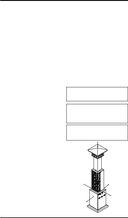
Gas Light
(Inside Deco
Shroud)
Burner
(Behind Grill)
Control
Knob
On/Off |
Electronic |
|
Ignitor |
||
Switch |
||
|
Cabinet
Base
Assembly
Figure 2 - Outdoor Patio Heater with Light
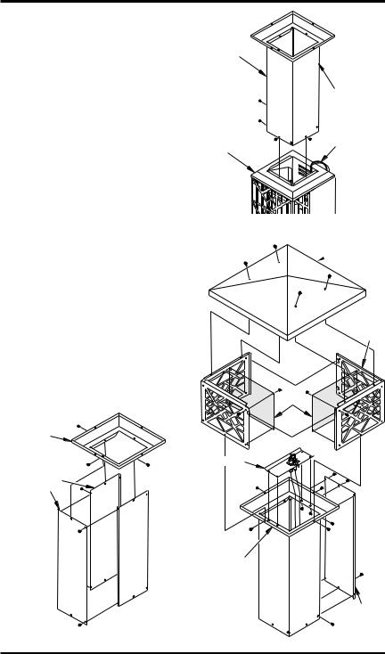
Unpacking Heater
Check all items for shipping damage. If heater is damaged, promptly inform dealer where you bought heater.
1.Remove base and weight from box.
2.Remove top cap, 2 deco light shrouds, top and packaging materials from box. Set parts aside in a safe location.
3.Remove burner assembly from box, leaving packaging materials on bottom of assembly. Set aside in the upright position.
4.Remove lightpost pieces, cabinet base and tank door from box. Set aside.
www.desatech.com |
118994-01G |
Assembly
Estimated assembly time: 45 minutes Tools required:
•#2 Phillips screwdriver
•9/16" and 5/16" Open end wrenches
Hardware packet provided with heater may contain more parts than needed for heater assembly.
Hardware packet contains the following items shown on pages 10 through 13:
Electronic Ignitor (1), Ignitor Wire (1), Ground Wire (1), Valve Knob (1), Propane Tank RetentionChain(1),RetentionHook(2),DBatteries(2) and AA Battery (1).
Parts are referenced by designated letter throughout assembly instructions. Hardware packet contains the following (quantity used in parenthesis):
Description |
|
|
Part No. |
A 1 1/2" Screw (8) |
|
|
119619-01 |
B 7 mm Washer (8) |
|
119600-04 |
|
C 5/8" Screw (9) |
|
|
119619-03 |
D 5 mm Washer (9) |
|
119600-02 |
|
E Hex Nut No. 10 (9) |
|
NPC-3C |
|
F 3/8" Screw (20) |
|
|
119619-06 |
G Hex Nut (20) |
|
|
NPC-1C |
H 3/8" Self tapping screw (34) |
119620-02 |
||
I 2 1/4" Hex Bolt (2) |
|
|
HC4-18C |
J 5/16" Hex Nut (2) |
|
NPC-5C |
|
B |
E |
|
|
A |
F |
I |
J |
C |
|||
G 
D |
H |
|
|
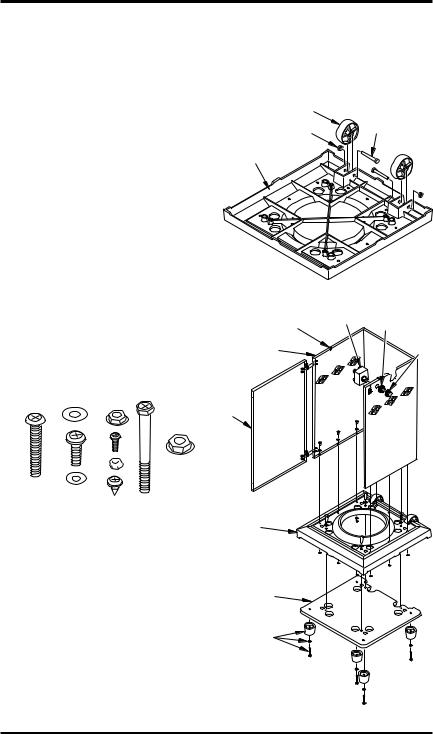
Base Assembly |
|
1.Turn base upside down. Attach 2 wheels, 2 axles (I) and 2 nuts (J) as shown in Figure 3. Do not overtighten.
2.Attach 4 base feet to base weight with 4 washers (B) and 4 screws (A) as shown in Figure 4. Feet will install over raised areas underneath base weight.
3.Being careful not to scratch paint, lay cabinet base onto back side (use foam packaging block to support rear top of cabinet base). Align holes in bottom edges of cabinet base with holes in base as shown in Figure 4. Attach with 1 screw (C), 1 washer (D) and 1 nut (E) for each of the 9 holes (see Figure 4). Set assembly upright.
4.Attach base to weight with 4 screws (A) and 4 washers (B) as shown in Figure 4.
5.Install chain retainers (“S” hooks) to upper edges of cabinet base as shown in Figure 4.
6.Install electronic ignitor through cabinet wall as shown in Figure 4. Hand tighten.
7.Attach tank door to cabinet with 4 screws
(F) and 4 nuts (G) as shown in Figure 4. Set entire assembly aside.
Wheel |
|
Nut |
Axle |
|
Base
Figure 3 - Attaching Wheels to Base
Chain |
Ignitor |
Retainer |
|
Retainer |
Ring |
||
|
|||
|
|
Ignitor |
|
Cabinet |
|
Cap |
|
|
|
||
Base |
|
|
Tank
Door
Base
Base
Weight
Base Foot,
Washer and
Hex Bolt
Figure 4 - Cabinet Base Assembly
118994-01G |
www.desatech.com |
Assembly
Continued
Burner and lightpost assembly
1.Locate 4 lightpost panels that are packaged together. Assemble 3 of the pieces with 4 screws (H) as shown in Figure 5.
2.Place lightpost top over panel assembly aligning screw holes. Attach with 3 screws
(H) as shown in Figure 5.
3.Pilot light and wiring has been placed inside top of burner assembly for shipping. Carefully remove pilot from inside assembly and let wiring and pilot hang down back of assembly.
4.Place lightpost panels and top assembly on top of burner assembly aligning back side of each assembly. See Figure 6. Attach with 3 screws (H).
5.Place pilot assembly on top of lightpost top as shown in Figure 7. Attach with 4 screws (H). Check wire connections before proceeding.
6.Attach 4 light shroud screens to light shrouds with 4 screws (F) and 4 nuts (G) each as shown in Figure 7. Only 2 of the 4 screens are shown.
7.Place deco light shrouds on top of lightpost top (see Figure 7). Make sure fanges are on top. Slide shroud tabs together. Attach to lightpost top with 4 screws (H) through holes in bottom of shroud pieces (see Figure 7). Tighten all screws.
8.Attach lightpost top cap to shroud assembly with 4 screws (H) as shown in Figure 7.
Lightpost |
|
Assembly |
Open Side |
|
|
|
of Panel |
|
Assembly |
|
to Back of |
|
Heater |
Burner |
Pilot Light |
Assembly |
Wiring to |
|
Back of |
|
Heater |
Figure 6 - Connecting Lightpost and
Burner Assembly
Lightpost
 Top Cap
Deco
Light
Shroud
Screen |
Lightpost |
|
Top |
Pilot |
|
|
|
Assembly |
Lightpost
Panels
|
Lightpost |
|
Top |
|
Fourth |
|
Lightpost |
Figure 5 - Lightpost Panels and Top |
Panel |
Assembly |
Figure 7 - Attaching Pilot and Shroud |
www.desatech.com |
118994-01G |
Assembly
Continued
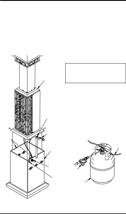
Heater assembly
Note: If needed, acquire assistance lifting assembly.
1.Place entire lightpost assembly on top of cabinet base assembly. Attach with 4 screws (H) as shown in Figure 8. Install 2 screws (H) into holes on each side of control valve. Attach control valve nut and control knob to control valve.
2.Connect 2 brown wires to ON/OFF switch.
3.Connect white ground wire attached to cabinet to right post on electronic ignitor. Remove wire tie. Connect black ignitor wire to left post on electronic ignitor. Install battery in ignitor as shown on page 12.
4.Install batteries in battery holder as shown on page 12. Do not mix batteries.
5.Connect regulator to gas cylinder, see Operation. Gas cylinder will sit inside of cabinet assembly.
6.Check for leaks. See Checking for Leaks page 8.
7.Attach fourth lightpost panel to assembly with 6 screws (H) as shown in Figure 7, page 6.
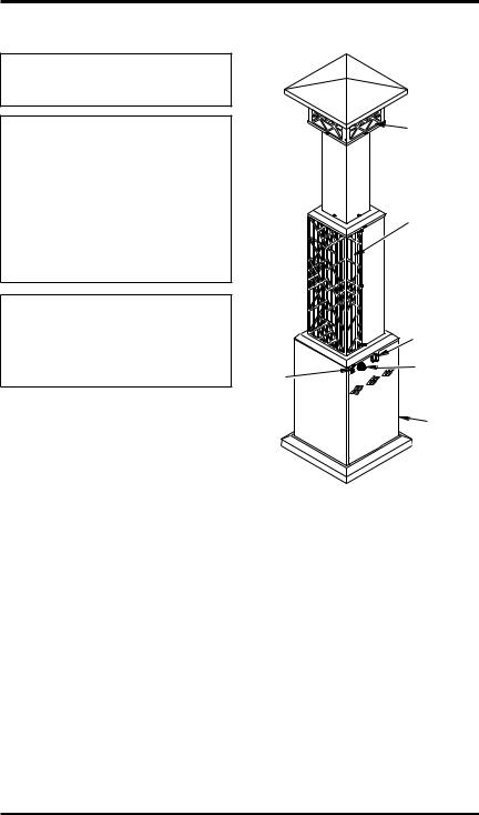
Operation
Lightpost/
Burner
Assembly
|
Control |
|
Valve |
|
Control |
|
Valve Nut |
Chain |
and Control |
Retainer |
Knob |
|
Cabinet |
|
Assembly |
|
Ignitor |
|
ON/OFF |
|
Switch |
Figure 8 - Attaching Lightpost/Burner
Assembly to Cabinet Assembly
 CAUTION: Do not stand in front of heater while lighting.
Stand at the side when lighting the heater.
Use only a 20 lb. propane/LP cylinder (not included). See safety information for proper cylinder selection. Connect the hose/regulator assembly to the cylinder (see Figure 9). The hose should already be connected to the heater. Connect hose to the valve inlet (see
Figure 9). Tighten firmly using a wrench.
Route retention chain through at least one of the handles of the propane/LP tank (see Figure 9). Make sure to route chain through handle on tank and NOT around tank valve. Chain must not interfere with valve. Attach hooks on both ends of chains to chain retainers installed on cabinet base (see Figure 8).
|
Retention |
Valve Inlet |
Chain |
|
Hose/Regulator
Assembly
20 lb.
Propane/LP
Cylinder
Figure 9 - Connecting Hose/Regulator
Assembly to Propane/LP Cylinder
118994-01G |
www.desatech.com |
Operation
Continued
Checking for leaks
1.Turn heater valve to OFF position.
2.Turn cylinder supply valve fully counter clockwise to OPEN position.
3.Use a noncorrosive leak detection solution to check the connection for leaks before attempting to light heater. If leak is found, turn cylinder valve to CLOSE and do not use until all leaks are corrected.
Lighting instructions
Gas Light
1.Press power switch to ON, gas light will automatically light.
2.Press power switch to OFF to turn gas light off.
3.To turn off gas supply to gas light, turn knob on manual shutoff valve to OFF. Manual shutoff valve is located on gas train assembly inside of heater cabinet.
Note: Be sure manual shutoff valve is in the ON position to operate gas light.
Main Burner
1.Push heater control knob in and turn counter clockwise to the START position.
2.Push control knob in and press ignitor button. Repeat until heater is lit.
3.Continue holding knob in for approximately 30 seconds. Heater should remain lit in the LOW heat setting.
4.For more heat, press knob and rotate counterclockwise to HIGH setting.
5.If RELIGHTING, wait 5 minutes for heater to cool and gas to clear, then follow steps 1 through 3.
|
ON |
|
|
|
|
|
|
|
|
OFF |
|
|
OFF |
|
|
||
|
|
|
|
||
|
|
|
|
|
|
GAS LIGHT |
IGNITOR |
|
|||
POWER SWITCH |
START-LOW |
||||
|
|||||
HIGH
Figure 10 - Gas Light Heater Controls
Shutdown Instructions
1.Press control knob and rotate clockwise to OFF position.
2.Close propane/LP cylinder valve (rotate knob clockwise).
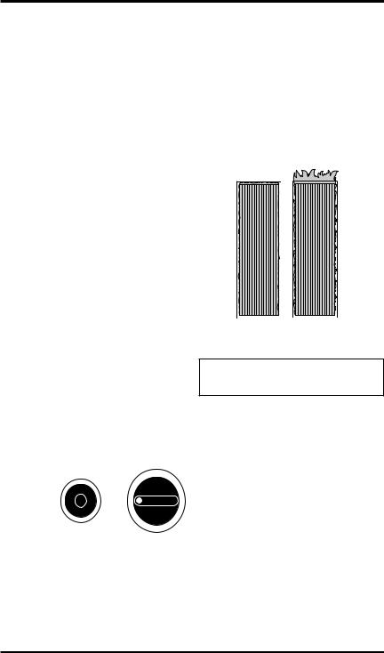
BURNER OPERATION
Visually inspect burner for proper operation. The burner should glow red with a minimum amount of fame lap after initial firing. If fame lap on burner is excessive, have heater serviced. Pressure may be too high or nozzle/ burner may be damaged.
Correct |
Incorrect |
Flame |
Flame |
Pattern |
Pattern |
Figure 11 - Burner Operation
Storage
 CAUTION: Disconnect heater from propane/LP supply cylinder.
1.Do not store heater while attached to propane/LP cylinder. Close cylinder valve. Remove the hose/regulator assembly from the propane/LP cylinder by turning the fuel gas connector nut clockwise.
2.Storage of heater inside is permissible only if the cylinder is disconnected and removed from the appliance.
3.Store propane/LP cylinder in safe manner. Refer to Chapter 5 of Standard for Storage andHandlingofLiquefiedPetroleumGases,
ANSI/NFPA 58. Follow all local codes. Cylinders must be stored outdoors in a well-ventilated area out of reach of children. Disconnected cylinders must have threaded valve plugs tightly installed, and must not be stored in a building, garage or any other enclosed area. Never store cylinders near high heat, open flame, or where temperatures exceed 100° F (38° C).
4.Store in a dry, clean, and safe place.
www.desatech.com |
118994-01G |
Maintenance
 WARNING: Never attempt to service heater while it is connectedtopropane/LPsupply, operating, or hot. Severe burns can occur. Any guard or other protective device removed for servicing must be replaced prior to operating the heater.
Specifications
•Rating: High - 36,500 Btu/Hr (10.7 kw) Low - 20,000 Btu/Hr (5.86 kw)
•Fuel: Propane Vapor Only
•Fuel Consumption/Hour: Min. 0.22 gal (0.83 liter), Max. 0.39 gal (1.48 liter)
Min. 0.93 lb (0.42 kg), Max 1.67 lb (0.76 kg)
•Supply Pressure (To Regulator): Maximum - 200 psi (1,379 Kpa) Minimum, for input adjustment - 5 psi (34.5 Kpa)
1.Keep heater clean. Remove any debris from ventilation openings.
2.Inspect heater before each use. Check connections for leaks. Apply mixture of liquid soap and water to connections. Bubbles forming show a leak that must be corrected. Correct all leaks at once.
3.Inspect hose/regulator assembly before each use. If hose is highly worn or cut, replace it immediately. At least annually, remove hose/regulator assembly from heater to inspect entire length of hose. Replacement hose must be same type as supplied with unit.
4.Spiders and insects can create a dangerous condition that may damage heater or make it unsafe. Keep burner area clean of all spiders, webs, or insects.
5.Have heater inspected yearly by a qualified service person.
•Manifold Pressure: High - 1 psi (6.89 kPa), Low - 0.98 psi (6.77 kPa)
•Ignitor Gap: 0.120"
•Minimum Temperature: -20°F (29°C) Surrounding Air Temperature
•Heater Size (L x W x H):
18" x 17.125" x 82" (0.45 x 0.43 x 2.1 m)
•Carton Size (L x W x H):
38.625" x 18.125" x 18" (0.98 x 0.46 x 0.45 m)
•Heater Weight: 96 lb (43.5 kg)
•Shipping Weight: 110 lb (49.9 kg)
Wiring Diagram
Electronic
Ignitor
|
|
|
|
|
|
|
|
|
|
|
|
|
|
|
|
|
|
|
|
|
|
|
|
|
|
|
|
|
|
|
|
|
|
|
|
Brown |
|
|
|
White |
|
|
|
|
|
|
|
|
|||||||||||
Ignitor Electrode |
|
|
|
|
|
|
|
|
|
|
|
|
|
|
|
|
Thermocouple |
|
|
||||||||||
|
|
|
|
|
|
|
|
|
|
|
|
|
Ground |
|
Brown |
|
|||||||||||||
|
|
|
|
|
|
|
|
|
|
|
|
|
|
|
|||||||||||||||
|
|
|
|
|
|
|
|
|
|
|
|
|
|
|
|
|
|
|
|
|
|
|
|
||||||
|
|
Gas Light |
|
|
|
|
|
|
|
|
|
|
|
|
|
|
|
|
|
||||||||||
|
|
|
|
|
|
|
|
|
|
|
|
|
|
|
|
|
|
|
|
|
|
|
|
|
|
||||
|
|
|
Burner |
|
|
|
|
|
|
|
|
Ground |
|
|
|
|
|
|
|
|
|||||||||
|
|
|
|
|
|
|
|
|
|
|
|
|
|
|
Gas Valve |
|
|||||||||||||
White |
|
|
White |
|
|
|
|
|
|
|
|
|
|
|
|
|
|
|
|
|
|||||||||
|
|
|
|
|
|
|
|
|
|
|
|
|
Black |
|
|
|
|
|
|
|
|
|
|||||||
|
|
I |
S |
|
|
|
Orange |
|
|
Control |
|
|
|
ON/OFF |
|||||||||||||||
|
|
|
|
|
|
|
|
|
|
|
|
|
|
|
Valve |
|
|
|
|
||||||||||
|
|
|
|
|
|
|
|
|
|
|
|
|
|
|
|
|
|||||||||||||
|
|
|
|
|
|
|
|
|
|
|
|
|
|
|
|
|
|
|
|
|
|
|
|
|
|
|
Switch |
||
|
|
|
|
|
|
|
|
|
|
|
|
|
|
|
|
|
|
|
|
|
|
|
|
|
|
|
|
|
|
|
|
|
|
|
|
|
|
|
|
|
|
|
Brown |
|
|
|
|
|
|
|
|||||||||
|
|
|
|
|
|
|
|
|
|
|
|
|
|
|
|
|
|
|
|
|
|||||||||
|
|
|
|
|
|
|
|
|
|
|
|
|
Brown |
|
|
|
|
|
|
|
|
||||||||
|
|
Control Module |
|
|
|
Red |
|
|
|
|
|
|
|
|
|||||||||||||||
|
|
|
|
|
Black |
|
|
Battery |
|
||||||||||||||||||||
|
|
|
|
|
|
|
|
|
|
|
|
|
|
|
|
|
|
|
|
|
|
|
|
Holder |
|
||||
|
|
|
|
|
|
|
|
|
|
|
|
|
|
|
|
|
|
|
|
|
|
|
|||||||
|
|
|
|
|
|
|
|
|
|
|
|
|
|
|
|
|
|
|
|
|
|
|
|
|
|
|
|
|
|
118994-01G |
www.desatech.com |

Illustrated Parts Breakdown
Cabinet assembly
Models TD100, TD102, TD104 AND TD110
1 |
6 |
2
2 7
9
18
8
3
10
4
4
11
4
4
5
14
19
12 |
13 |
|
15
16
17
10 |
www.desatech.com |
118994-01G |
Parts List
Cabinet assembly
Models TD100, TD102, TD104 AND TD110
This list contains replaceable parts used in your heater. When ordering parts, follow the instructions listed under Replacement Parts, page 15.
|
|
|
TD100, |
TD110 |
TD102 |
KEY |
|
|
|
||
|
|
|
|
|
|
NO. PART NO. |
DESCRIPTION |
|
|
|
|
1 |
118890-01 |
Lightpost Top Cap |
|
• |
|
|
118890-02 |
Lightpost Top Cap |
• |
|
|
2 |
118891-01 |
Deco Light Shroud Assembly, Mission |
• |
• |
|
|
118891-02 |
Deco Light Shroud Assembly, Ornate |
|
|
|
3 |
118892-01 |
Lightpost Top |
|
• |
|
|
118892-02 |
Lightpost Top |
• |
|
|
4 |
118885-01 |
Lightpost Panel |
|
• |
|
|
118885-02 |
Lightpost Panel |
• |
|
|
5 |
118884-01 |
Lower Burner Housing Top |
|
• |
|
|
118884-02 |
Lower Burner Housing Top |
• |
|
|
6 |
118887-01 |
Refector Right/Left |
• |
• |
|
7 |
118888-01 |
Refector Top |
• |
• |
|
8 |
118889-01 |
Refector Bottom |
• |
• |
|
9 |
118883-01 |
Lower Burner Housing |
|
• |
|
|
118883-02 |
Lower Burner Housing |
• |
|
|
10 |
118882-01 |
Cabinet Base Top |
|
• |
|
|
118882-02 |
Cabinet Base Top |
• |
|
|
11 |
119004-01 |
Lower Screen |
• |
• |
|
12 |
118900-01 |
Front Lower Burner Grate, Mission |
• |
• |
|
|
118900-02 |
Front Lower Burner Grate, Ornate |
|
|
|
13 |
118905-01 |
Base Cabinet Door |
|
• |
|
|
118905-02 |
Base Cabinet Door |
• |
|
|
14 |
118881-01 |
Cabinet Base |
|
• |
|
|
118881-02 |
Cabinet Base |
• |
|
|
15 |
118899-01 |
Lightpost Base |
• |
• |
|
16 |
118901-01 |
Lightpost Base Weight |
• |
• |
|
17 |
118902-01 |
Base Foot |
• |
• |
|
18 |
119005-01 |
Upper Screen |
• |
• |
|
19 |
118849-01 |
Wheel |
• |
• |
|
* |
119423-01 |
Accessory Cover (not shown) |
|
|
|
* Available as accessory for models TD100, TD102 and TD110.
TD104
•
•
•
•
•
•
•
•
•
•
•
•
•
•
•
•
•
•
•
•
QTY.
1
1
2
2
1
1
4
4
1
1
2
1
1
1
1
1
1
1
1
1
1
1
1
1
1
1
4
4
2
1
118994-01G |
www.desatech.com |
11 |
Illustrated Parts Breakdown
Gas components
Models TD100, TD102, TD104 AND TD110
1
Do not mix old and new batteries. Do not mix alkaline, standard (carbon - zinc) or rechargeable (nickel - cadmium) batteries.
D Batteries
6
7
8
9
2
3
5 21
4
10
18
2
17
11
13
AA
Battery
Positive
UP
20
19
12
16
15
14
12 |
www.desatech.com |
118994-01G |

Parts List
Gas components
Models TD100, TD102, TD104 AND TD110
This list contains replaceable parts used in your heater. When ordering parts, follow the instructions listed under Replacement Parts, page 15.
KEY |
|
|
|
|
|
NO. |
PART NO. |
DESCRIPTION |
QTY. |
||
1 |
118893-01 |
Light Post Burner Bracket |
1 |
||
2 |
120373-01 |
Top Light Burner Assembly |
1 |
||
3 |
118904-01 |
Lightpost Burner Flex Line |
1 |
||
4 |
120570-01 |
Ignitor Electrode Kit |
1 |
||
5 |
118906-02 |
Thermocouple |
1 |
||
6 |
119091-01 |
Lightpost Main Burner |
1 |
||
7 |
118911-01 |
Main Burner Orifice |
1 |
||
8 |
119472-01 |
Orifice Nut |
1 |
||
9 |
118913-01 |
Main Burner Tube |
1 |
||
10 |
098271-11 |
Radiant Ignitor Wire |
1 |
||
11 |
118868-02 |
Main Burner Control Valve |
1 |
||
12 |
113793-01 |
Manual Shutoff Valve |
1 |
||
13 |
118914-01 |
Valve Flex Line |
1 |
||
14 |
099393-02 |
Valve Knob |
1 |
||
15 |
098508-01 |
Control Nut |
1 |
||
16 |
119293-01 |
Outlet Fitting |
1 |
||
17 |
118907-01 |
Outlet T Fitting |
1 |
||
18 |
111435-01 |
Electronic Ignitor |
1 |
||
19 |
118909-01 |
Outlet Elbow |
1 |
||
20 |
118896-01 |
Lightpost Component Plate |
1 |
||
21 |
100898-01 |
Thermocouple Nut |
2 |
||
|
|
|
PARTS AVAILABLE - NOT SHOWN |
|
|
|
|
|
|
|
|
|
119111-01 |
|
Hardware Blister Pack |
1 |
|
|
119093-01 |
Regulator and Hose Assembly |
1 |
||
|
103158-01 |
Magnetic Door Catch |
2 |
||
|
119110-01 |
Propane Tank Retention Chain |
1 |
||
|
120574-01 |
Retention Hook |
2 |
||
|
118990-02 |
Control Position Decal, English |
1 |
||
|
118990-03 |
Control Position Decal, Spanish/French |
1 |
||
|
118990-04 |
Control Position Decal, Eng/Spn/Frn |
1 |
||
|
118988-02 |
Warning Decal |
1 |
||
|
118989-02 |
|
Model Data Decal |
1 |
|
|
100639-13 |
|
Caution Decal |
1 |
|
|
119297-01 |
|
Regulator Label |
1 |
|
118994-01G |
www.desatech.com |
13 |

Troubleshooting
 WARNING: Never attempt to service heater while it is connected to propane/LP supply, operating, or hot. Severe burns can occur.
SYMPTOM |
POSSIBLE CAUSE |
REMEDY |
||
|
|
|
|
|
Burner fails to light |
1. Propane/LP supply valve |
1. |
Open propane/LP supply |
|
|
|
closed on propane/LP cyl- |
|
valve slowly |
|
|
inder |
|
|
|
2. |
Blockage in burner/orifice |
2. |
Cleanburner/replaceorifice |
|
|
elbow/hose and regulator |
|
elbow/hose and regulator |
|
|
assembly |
|
assembly |
|
3. |
Battery not installed, battery |
3. |
Install new alkaline battery |
|
|
power low or battery not |
|
in electronic ignitor. Verify |
|
|
installed correctly |
|
battery is installed correctly. |
|
|
|
|
See page 12 |
|
|
|
|
|
Burner lights but goes out |
1. Not enough warm-up time |
1. |
Relight, hold automatic |
|
when automatic control valve |
|
|
|
control valve button in 30 |
button is released |
|
|
|
seconds |
|
2. |
Low gas pressure |
2. |
Check propane/LP cylinder |
|
|
|
|
for proper gas supply |
|
3. |
Thermocouple loose or |
3. |
Tighten connection or re- |
|
|
needs to be replaced |
|
place thermocouple |
|
4. |
Automatic control valve |
4. |
Replace automatic control |
|
|
needs to be replaced |
|
valve assembly |
|
5. |
Thermocouple gap is too |
5. |
Tip of thermocouple should |
|
|
great |
|
just touch the emitter mate- |
|
|
|
|
rial. Loosen bracket screws |
|
|
|
|
to move thermocouple clos- |
|
|
|
|
er to burner. Be careful not |
|
|
|
|
to allow ignitor to touch. |
|
|
|
|
Maintain 0.20" |
|
|
|
|
|
Maximum burn rate is low |
1. Low gas pressure |
1. |
Check gas supply; check |
|
|
|
|
|
regulator output |
|
2. |
Low fuel supply |
2. |
Consult propane/LP gas |
|
|
|
|
supplier |
|
3. |
Restriction in burner/orifice |
3. |
Cleanburner/replaceorifice |
|
|
elbow/hose and regulator |
|
elbow/hose and regulator |
|
|
assembly |
|
assembly |
14 |
www.desatech.com |
118994-01G |

Replacement Parts
 WARNING: Use only original replacement parts. This heater must use design-specific parts.
Do not substitute or use generic parts. Improper replacement parts could cause serious or fatal injuries. This will also protect yourwarrantycoverageforparts replaced under warranty.
Parts Under Warranty
Contact authorized dealers of this product. If they can’t supply original replacement part(s), either contact your nearest Parts Central or call DESA Heating Products’ Technical Service Department at 1-866-672-6040.
When calling DESA Heating Products, have ready
•your name
•your address
•model and serial numbers of your heater
•purchase date
•how heater was malfunctioning
In most cases, we will ask you to return the part to the factory.
Parts Not Under Warranty
Contact authorized dealers of this product. If they can’t supply original replacement part(s), either contact your nearest Parts Central listed in the Authorized Service Center booklet supplied with heater or call DESA Heating Products (US) at 1-866-672-6040 or DESA Industries (CAN) at 1-415-255-5677 for referral information.
When calling DESA Heating Products, have ready
•model and serial number of your heater
•the replacement part number
Technical Service
You may have further questions about installation, operation, or troubleshooting. If so, contact DESA Heating Products’ Technical Service Department at 1-866-672-6040. When calling please have your model and serial numbers of your heater ready.
You can also visit DESAHeating Products’ technical service web site at www.desatech.com.
Accessory
Purchase accessories and parts from your nearest dealer or service center. If your dealer or service center can not supply an accessory or part, either contact your nearest Parts
Central (listed in the separate Authorized
Service Center booklet) or call DESA Heating Products (US) at 1-866-672-6040 or DESA Industries (CAN) at 1-415-255-5677 for referral information. You can also write to the address listed on the back page of this manual.
Patio Heater Cover - 119423-01
A heater cover accessory may be purchased to protect your patio heater. Made of black polyester material with Outdoor Leisure logo.
Patio heater cover accessory may be ordered through this website:
www.aboutoutdoorleisure.com
Click “Online Outlet”.
Click “Patio Heaters”.
Click “Accessories”.
118994-01G |
www.desatech.com |
15 |
Warranty Information
LIMITED WARRANTY
DESA Heating, LLC warrants this product and any parts thereof, to be free from defects in materials and workmanship for one (1) year for residential home owner usage or 90 days for commercial/industrial usage from the date of first purchase when operated and maintained in accordance with instructions. This warranty is extended only to the original retail purchaser, when proof of purchase is provided.
This warranty covers only the cost of parts and labor required to restore the product to proper operating condition. Transportation and incidental costs associated with warranty repairs are not reimbursable under this warranty.
Warranty service is available only through authorized dealers and service centers.
This warranty does not cover defects resulting from misuse, abuse, negligence, accidents, lack of proper maintenance, normal wear, alteration, modification, tampering, contaminated fuels, repair using improper parts, or repair by anyone other than an authorized dealer or service center. Routine maintenance is the responsibility of the owner.
THIS EXPRESS WARRANTY IS GIVEN IN LIEU OF ANY OTHER WARRANTY EITHER EXPRESSED OR IMPLIED, INCLUDING WARRANTIES OF MERCHANTABILITY AND FITNESS FOR A PARTICULAR PURPOSE.
DESA Heating, LLC assumes no responsibility for indirect, incidental or consequential damages. Some states do not allow the exclusion or limitation of incidental or consequential damages or limitations or exclusions may not apply to you. This Limited Warranty gives you specific legal rights and you may also have other rights which vary from state to state.
This warranty does not cover discoloration due to operation of heater. The only warranty applicable is our standard written warranty. We make no other warranty, expressed or implied.
WARRANTY SERVICE
Should your heater require service, return it to your nearest authorized service center. Proof of purchase must be presented with the heater. The heater will be inspected. A defect may be caused by faulty materials or workmanship. If so, DESA Heating, LLC will repair or replace the heater without charge.
REPAIR SERVICE
Return the heater to your nearest authorized service center. Each Service Center is independently owned and operated. Repairs not covered by the warranty will be billed at standard prices.
For information about this warranty write:
DESA Heating, LLC |
|
|
|
|
|
|
|
||
82 Akron Road |
||||
2701 Industrial Drive |
||||
P.O. Box 90004 |
Toronto, Ontario |
|||
Bowling Green, KY 42102-9004 |
M8W 1T2 |
|||
www.desatech.com |
416-255-5333 |
|||
|
www.desatech.com |
|||
118994-01 Rev. G 03/07
Loading...