How it Works
Log In / Sign Up
0
My Files
0
My Downloads
329194
History
Account Settings
Log Out
Buy Points
How it Works
FAQ
Contact Us
Questions and Suggestions
Users
Desa
Loading...
T
TD120
TD120A
Td125
TT30 10
U
UNVENTED GAS LOG HEATER
UNVENTED NATURAL GAS FIREPLACE
UNVENTED PROPANE GAS LOG HEATER
Unvented Propane Gas Log Heater Split Oak
V
V3612ST
V368ST
V36EN-A
V36EP-A
V36NR-B
V42N-A
V50S
VB36
VC36H
VC36NE
VC42P
VC42PE
VCB36NE
VCBK4L
VCD36RN
VCD36RNE
VDCFTNA
VDCFTPA
VDDVF36STN-STP
VDVC42BH
VDVF36
VDVF36PN-PP
VDVF36TCLPE
VE36LBHB
Vent-Free Gas and Electric Hearth
VESBL
VF-18N-EMU
VF-18P-BTB
VF-24N-BTB
VF-24N-MHD
VF-24N-PDG
VF-24P-PJD
VF-30P-PJD
VF48HiR
VFN18R
VFN24MV
VFP18MV
VFP18R
VFRMV18PA
VFRMV24NB
VG36H
VG42H-50H
VGC18NR
VGC18PR
VGC30PR
VGL24NR
VGL30PRA
VGL450N
VgM36h
VGMRN
VGN30B
VI33NR
VI33NRA
VI33NRB
VJM50
VK36EN
VK42N
VK42P
VKC36N
VKC42N
VKC42P
VKC42PE
VM36E
VM36P
VM42E
Vm42eP
VM42P
VM42PB-H
VMH10TP
VMH10TPA
VMH26PR8
VMH26TNC
VMH3000TNA
VML27NR
VML27PR
VN10
VN1000BTA
VN10TA
VN20BT
VN20BTA
VN2550ITA
VN2800BTA
VN2800BTB
VN2800BTC
VN2800BTD
VN3000C
VN30TA
VP1000BA
VP1000BTA
VP10A
VP10T
VP11
Loading...
Loading...
Nothing found
VGC18NR
User Manual
36 pgs
2.46 Mb
0
Owner's Operation And Installation Manual
36 pgs
2.53 Mb
0
Owner's Operation And Installation Manual
36 pgs
2.72 Mb
0
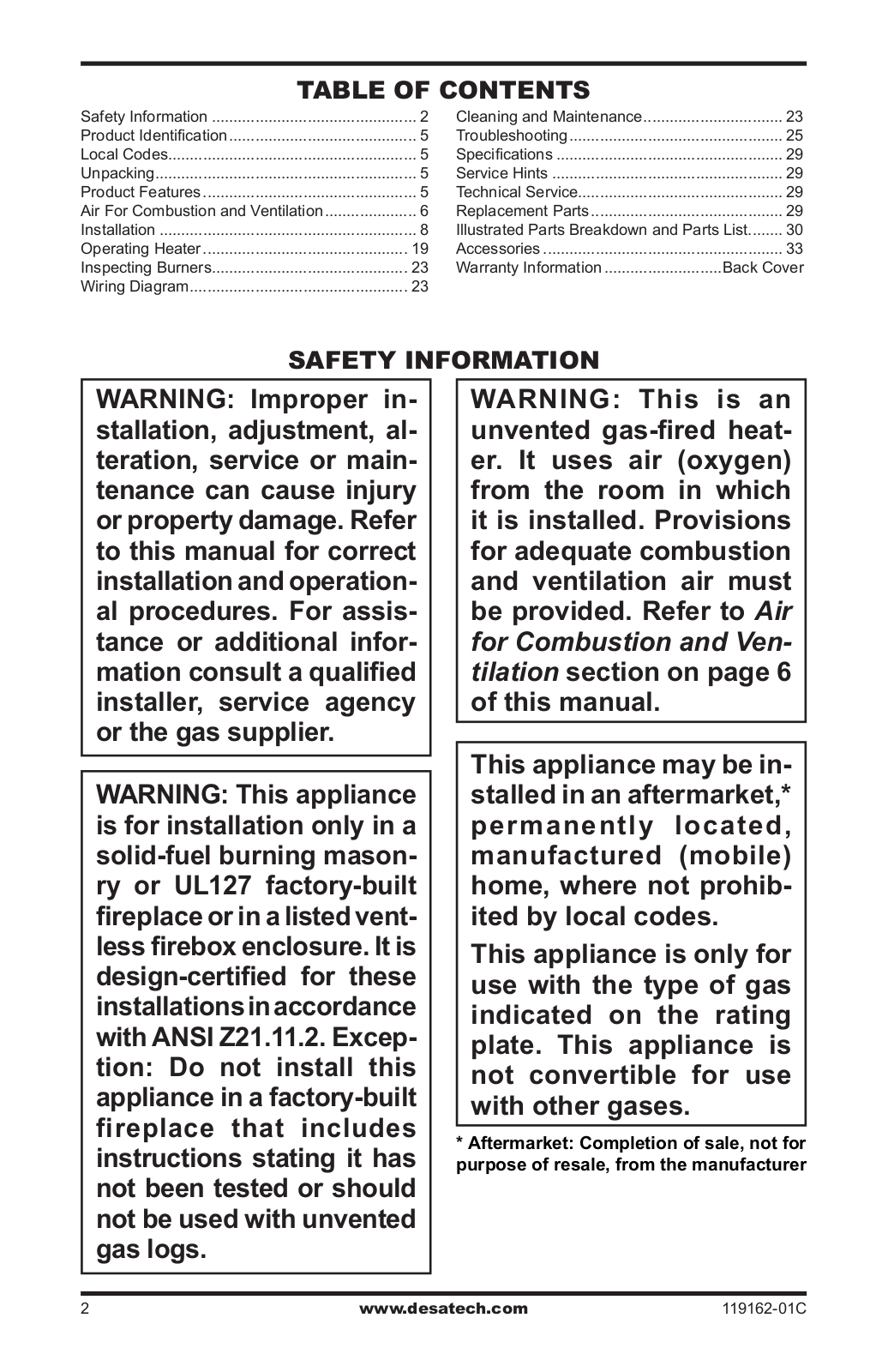
Table of contents
Loading...
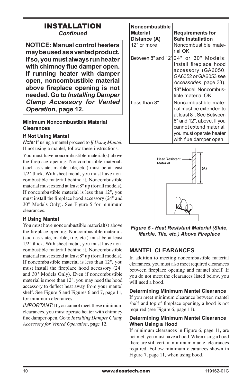
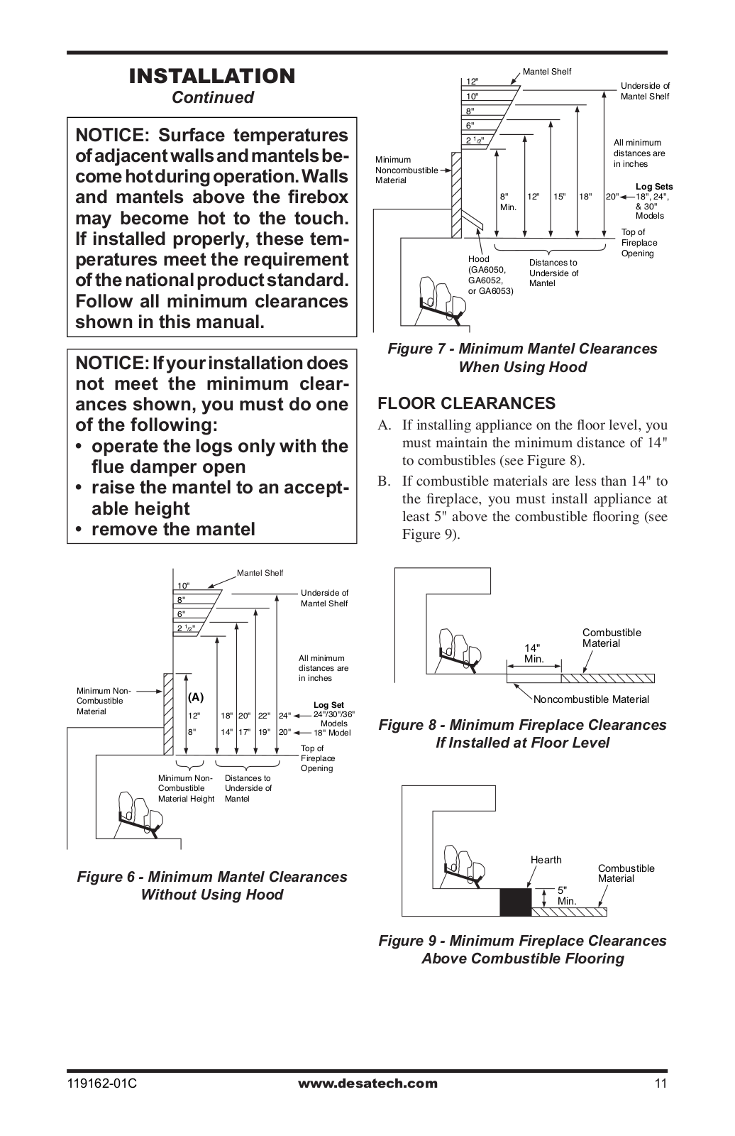
Desa VGC18NR, VGC24NR, VGC30NR User Manual
...
Desa User Manual
Download
Loading...
+
25
hidden pages
Unhide
You need points to download manuals.
1 point = 1 manual.
You can buy points or you can get point for every manual you upload.
Buy points
Upload your manuals
 Loading...