

VENT-FREE BLUE FLAME
GAS HEATER
SAFETY INFORMATION AND
INSTALLATION MANUAL
For more information, visit www.desatech.com
For more information, visit www.desatech.com
CR94-001 UNVENTED
ROOM HEATER
GCN20T, GCP20T
WARNING: If the information in this manual is
not followed exactly, a fire or explosion may
result causing property damage, personal injury, or loss of life.
— Do not store or use gasoline or other
flammable vapors and liquids in the vicinity
of this or any other appliance.
— WHAT TO DO IF YOU SMELL GAS
• Do not try to light any appliance.
• Do not touch any electrical switch; do not
use any phone in your building.
• Immediately call your gas supplier from a
neighbor’s phone. Follow the gas
supplier’s instructions.
• If you cannot reach your gas supplier, call
the fire department.
— Installation and service must be performed
by a qualified installer, service agency, or
the gas supplier.
GCN6, GCP6
GCN10T, GCP10T
Unvented room heaters are for installation in SINGLE FAMILY TYPE RESIDENCES ONLY, and the installation is
limited to ONE (1) unit per residence.
WARNING: Improper installation, adjustment, alteration, service, or maintenance
can cause injury or property damage.
Refer to this manual for correct installation and operational procedures. For assistance or additional information consult a qualified installer, service agency,
or the gas supplier.
WARNING: This is an unvented gas-fired
heater. It uses air (oxygen) from the room
in which it is installed. Provisions for adequate combustion and ventilation air must
be provided. Refer to
and Ventilation
on page 4 of this manual.
Air For Combustion
This appliance is only for use with the type of gas indicated on the rating plate. This appliance is not
convertible for use with other gases.
*Aftermarket: Completion of sale, not for purpose of resale, from the manufacturer
Save this manual for future reference.
Save this manual for future reference.
TABLE OF CONTENTS
SAFETY INFORMATION
2
TABLE OF CONTENTS
SAFETY INFORMATION ............................................................ 2
UNPACKING............................................................................... 3
PRODUCT IDENTIFICATION ..................................................... 3
PRODUCT FEATURES .............................................................. 3
LOCAL CODES........................................................................... 4
AIR FOR COMBUSTION AND VENTILATION ........................... 4
INSTALLATION ........................................................................... 6
OPERATING HEATER.............................................................. 14
INSPECTING BURNER ............................................................ 15
CLEANING AND MAINTENANCE ............................................ 16
TROUBLESHOOTING .............................................................. 17
SAFETY INFORMATION
WARNINGS
IMPORTANT: Read this owner’s manual carefully and
completely before trying to assemble, operate, or service this heater. Improper use of this heater can cause
serious injury or death from burns, fire, explosion,
electrical shock, and carbon monoxide poisoning.
DANGER: Carbon monoxide poisoning may lead
to death!
Carbon Monoxide Poisoning: Early signs of carbon monoxide
poisoning resemble the flu, with headaches, dizziness, or nausea. If
you have these signs, the heater may not be working properly. Get
fresh air at once! Have heater serviced. Some people are more
affected by carbon monoxide than others. These include pregnant
women, persons with heart or lung disease or anemia, those under
the influence of alcohol, and those at high altitudes.
Natural and Propane/LP Gas: Natural and propane/LP gases are
fuel gases. Fuel gases are odorless. An odor-making agent is added
to fuel gases. The odor helps you detect a fuel gas leak. However,
the odor added to fuel gas can fade. Fuel gas may be present even
though no odor exists.
Make certain you read and understand all warnings. Keep this
manual for reference. It is your guide to safe and proper operation
of this heater.
ILLUSTRATED PARTS BREAKDOWN AND PARTS LIST ....... 20
SPECIFICATIONS..................................................................... 26
SERVICE CENTER/P ARTS CENTRAL .................................... 26
OWNER’S REGISTRA TION FORM .......................................... 27
REPLACEMENT PARTS .......................................................... 29
SERVICE HINTS....................................................................... 29
TECHNICAL SERVICE ............................................................. 29
SERVICE PUBLICATIONS ....................................................... 29
ACCESSORIES ........................................................................ 29
WARRANTY INFORMATION...................................... Back Cover
WARNING: Do not use a blower insert, heat
exchanger insert or other accessory not approved for
use with this heater.
Children and adults should be alerted to the hazard of
high surface temperature and should stay away to
avoid burns or clothing ignition.
Surface of heater becomes very hot when running
heater. Heater will remain hot for a time after shutdown. Allow surface to cool before touching.
Any safety screen or guard removed for servicing the
appliance must be replaced prior to operation the heater.
Due to high temperatures, the appliance should be
located out of traffic and away from furniture and
draperies.
Do not place clothing or other flammable material on or
near the appliance. Never place any objects on the heater.
Carefully supervise young children when they are in
the same room with heater.
WARNING: Any change to this heater or its
controls can be dangerous.
WARNING: Do not use any accessory not ap-
proved for use with this heater.
For more information, visit www.desatech.com
For more information, visit www.desatech.com
Make sure grill guard is in place before running
heater.
Keep the appliance area clear and free from combustible materials, gasoline, and other flammable vapors
and liquids.
112157-01A
SAFETY INFORMATION
Continued
SAFETY INFORMATION
UNPACKING
PRODUCT IDENTIFICATION
PRODUCT FEATURES
3
3
Installation and repair should be done by a qualified
service person. The appliance should be inspected
and serviced before use and at least annually by a
professional service person. More frequent cleaning
may be required due to excessive lint from carpeting,
etc. It is imperative that control compartments, burners and circulating air passageways of the appliance
be kept clean.
1. This appliance is only for use with the type of gas indicated on
the rating plate. This appliance is not convertible for use with
other gases.
2. Do not place propane/LP supply tank(s) inside any structure.
Locate propane/LP supply tank(s) outdoors.
3. Do not install in a bedroom or a bathroom.
4. If you smell gas
• Shut off gas supply
• Do not try to light any appliance
• Do not touch any electrical switch; do not use any phone in
your building
• Immediately call your gas supplier from a neighbor’s phone.
Follow the gas supplier’s instructions
• If you cannot reach your gas supplier, call the fire department
5. This heater needs fresh, outside air ventilation to run properly.
This heater has an Oxygen Depletion Sensing (ODS) safety
shutoff system. The ODS shuts down the heater if not enough
fresh air is available. See Air for Combustion and Ventilation,
pages 4 through 6.
6. Keep all air openings in the front and bottom of heater clear and
free of debris. This will insure enough air for proper combustion.
7. If heater and pilot shuts off unexpectedly, do not relight the
pilot until you provide fresh, outside air. If heater keeps shutting off, have it serviced.
8. Do not run heater
• where flammable liquids or vapors are used or stored
• under dusty conditions
9. Before using furniture polish, wax, carpet cleaner, or similar
products, turn heater off. If heated, the vapors from these products may create a white powder residue within burner box or
on adjacent walls or furniture.
10. Do not use heater if any part has been under water. Immediately call a qualified service technician to inspect the room
heater and to replace any part of the control system and any
gas control which has been under water.
11. Turn off heater and let cool before servicing. Only a qualified
service person should service and repair heater.
12. Operating heater above elevations of 4,500 feet (1 370 m) could
cause pilot outage due to lower levels of oxygen in the air.
13. T o prevent performance problems, do not use propane/LP fuel
tank of less than 100 lbs. (45 kg) capacity.
14. Provide adequate clearances around air openings.
15. Before using the heater, provide adequate ventilation. An area
of 10 square inches (65 cm2) of opening of a window or roof
vent is needed for adequate combustion and ventilation air.
UNPACKING
1. Remove heater from carton.
2. Remove all protective packaging applied to heater for shipment.
3. Check heater for any shipping damage. If heater is damaged,
promptly inform dealer where you bought heater.
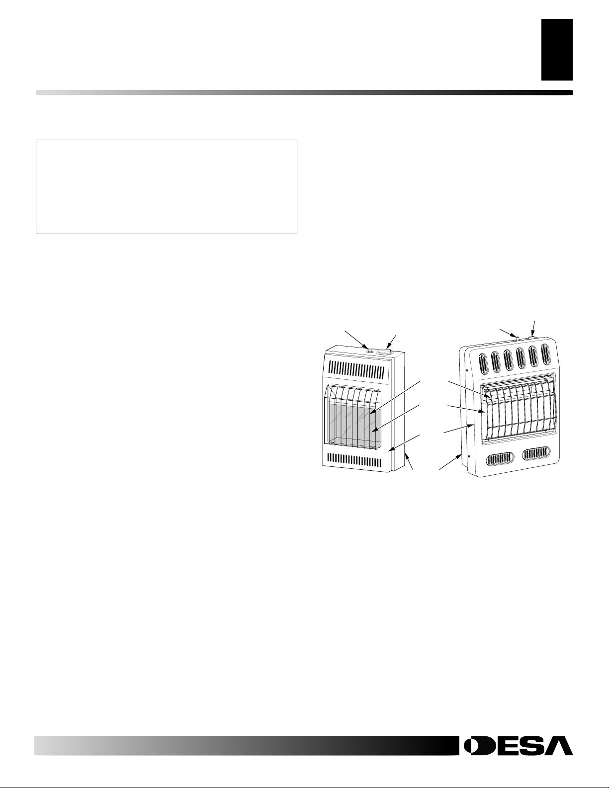
PRODUCT IDENTIFICATION
Piezo Ignitor
Button
6,000/10,000 Btu/Hr
Figure 1 - Vent-Free Gas Heater
Control Knob
Grill
Guard
Glass
Panel
Front
Panel
Heater
Cabinet
Piezo Ignitor
Button
Control Knob
20,000 Btu/Hr
PRODUCT FEATURES
SAFETY DEVICE
This heater has a pilot with an Oxygen Depletion Sensing (ODS)
safety shutoff system. The ODS/pilot is a required feature for ventfree room heaters. The ODS/pilot shuts off the heater if there is not
enough fresh air.
PIEZO IGNITION SYSTEM
This heater has a piezo ignitor. This system requires no matches,
batteries, or other sources to light heater.
THERMOSTATIC HEAT CONTROL
Thermostat models have a thermostat sensing bulb and a control
valve. This results in the greatest heater comfort. This can also result
in lower gas bills.
112157-01A
For more information, visit www.desatech.com
For more information, visit www.desatech.com
LOCAL CODES
AIR FOR COMBUSTION AND VENTILATION
4
Providing Adequate Ventilation
LOCAL CODES
Install and use heater with care. Follow all local codes. In the absence of
local codes, use the latest edition of CAN/CGA B149.1 Natural Gas
Installation Code or CAN/CGA B149.2 Propane Installation Code*.
*Available from www.csa.ca or 1-800-463-6727 (call your local
gas company for your local codes).
AIR FOR COMBUSTION AND
VENTILATION
WARNING: This heater shall not be installed in a
confined space or unusually tight construction unless provisions are provided for adequate combustion and ventilation air. Read the following instructions to insure proper fresh air for this and other fuelburning appliances in your home.
Today’s homes are built more energy efficient than ever. New materials, increased insulation, and new construction methods help reduce
heat loss in homes. Home owners weather strip and caulk around
windows and doors to keep the cold air out and the warm air in. During
heating months, home owners want their homes as airtight as possible.
While it is good to make your home energy efficient, your home
needs to breathe. Fresh air must enter your home. All fuel-burning
appliances need fresh air for proper combustion and ventilation.
Exhaust fans, fireplaces, clothes dryers, and fuel burning appliances
draw air from the house to operate. You must provide adequate fresh
air for these appliances. This will insure proper venting of vented
fuel-burning appliances.
PROVIDING ADEQUATE VENTILATION
The following are excerpts from CAN/CGA B149.1 Natural Gas
Installation Code or CAN/CGA B149.2 Propane Installation Code.
All spaces in homes fall into one of the three following ventilation
classifications:
1. Unusually Tight Construction
2. Unconfined Space
3. Confined Space
The information on pages 4 through 6 will help you classify your
space and provide adequate ventilation.
Unusually Tight Construction
The air that leaks around doors and windows may provide enough
fresh air for combustion and ventilation. However, in buildings of
unusually tight construction, you must provide additional fresh air.
Unusually tight construction is defined as construction
where:
a. walls and ceilings exposed to the outside atmosphere
have a continuous water vapor retarder with a rating of
one perm (6 x 10
ings gasketed or sealed
b. weather stripping has been added on openable windows
and doors
c. caulking or sealants are applied to areas such as joints
around window and door frames, between sole plates
and floors, between wall-ceiling joints, between wall panels, at penetrations for plumbing, electrical, and gas
lines, and at other openings.
If your home meets all of the three criteria above, you must
provide additional fresh air. See
doors
, page 6
If your home does not meet all of the three criteria above,
proceed to
page 5.
Determining Fresh-Air Flow For Heater Location,
and
.
-11
kg per pa-sec-m2) or less with open-
and
Ventilation Air From Out-
Confined and Unconfined Space
The Canadian Gas Association Certification Requirement, CGA
CR94-001 REV. 2 states that when combustion air supply is for the
unvented room heater only, it shall be sized at the rate of one (1)
square inch per 5000 BTU/HR (1.5 KW) from outdoors or the
manufacturer’s specification (whichever is greater). However, combustion air is acceptable when available from the principal heat
source and sized to the current CAN/CGA-B149.1 or .2 requirements. Where unvented equipment is installed in an area separated
from a combustion air supply by a door, then permanent openings,
grills or louvers shall be provided. One shall be within 18 inches (46
cm) from the ceiling and one 18 inches (46 cm) from the floor, sized
to one (1) square inch per 1000 BTU/HR (0.29 KW) to allow free
movement of air with the source of combustion air supply.
For more information, visit www.desatech.com
For more information, visit www.desatech.com
112157-01A
AIR FOR COMBUSTION AND
VENTILATION
Continued
AIR FOR COMBUSTION AND VENTILATION
Determining Fresh-Air Flow For Heater Location
5
5
DETERMINING FRESH-AIR FLOW FOR
HEATER LOCATION
Determining if You Have a Confined or
Unconfined Space
Use this work sheet to determine if you have a confined or unconfined space.
Space: Includes the room in which you will install heater plus any adjoining
rooms with doorless passageways or ventilation grills between the rooms.
1. Determine the volume of the space (length x width x height).
Length x Width x Height =___________ cu. ft. (m
space)
Example:
8 ft. (2.44 m) (ceiling height) = 2560 cu. ft. (72.6m3) (volume of space)
If additional ventilation to adjoining room is supplied with grills or open-
ings, add the volume of these rooms to the total volume of the space.
2. Multiply the space volume by 20 to determine the maximum Btu/Hr
(kW) the space can support.
__________ (volume of space) x 20 = [Maximum Btu/Hr (kW) the
Example:
[maximum Btu/Hr (kW) the space can support]
3. Add the Btu/Hr of all fuel burning appliances in the space.
* Do not include direct-vent gas appliances. Direct-vent draws combustion air from the outdoors and vents to the outdoors.
4. Compare the maximum Btu/Hr the space can support with the actual
amount of Btu/Hr used.
__________________
__________________ Btu/Hr (kW) (actual amount of Btu/Hr used)
Example:
Space size 20 ft. (6.1 m) (length) x 16 ft. (4.88 m) (width) x
space can support]
2560 cu. ft. (72.6m3) (volume of space) x 20 = 51,200
Vent-free heater _____________ Btu/Hr (kW)
Gas water heater* _____________ Btu/Hr (kW)
Gas furnace _____________ Btu/Hr (kW)
Vented gas heater _____________ Btu/Hr (kW)
Gas fireplace logs _____________ Btu/Hr (kW)
Other gas appliances* + _____________ Btu/Hr (kW)
Total = _____________ Btu/Hr (kW)
Example:
Gas water heater _____________ Btu/Hr (kW)
Vent-free heater + _____________ Btu/Hr (kW)
Total = _____________ Btu/Hr (kW)
51,200 Btu/Hr (15kW) (maximum the space can support)
60,000 Btu/Hr (17.6kW) [actual amount of Btu/Hr (kW)
used]
40,000 (11.7)
20,000 (5.9)
60,000 (17.6)
Btu/Hr (kW) (maximum the space can support)
3
) (volume of
The space in the above example is a confined space because the actual Btu/Hr
(kW) used is more than the maximum Btu/Hr (kW) the space can support.
You must provide additional fresh air. Your options are as follows:
A. Rework worksheet, adding the space of an adjoining room. If the
extra space provides an unconfined space, remove door to adjoining
room or add ventilation grills between rooms. See V entilation Air Fr om
Inside Building, page 6.
B. Vent room directly to the outdoors. See Ventilation Air From Out-
doors, page 6.
C. Install a lower Btu/Hr (kW) heater, if lower Btu/Hr (kW) size makes
room unconfined.
If the actual Btu/Hr used is less than the maximum Btu/Hr (kW) the space
can support, the space is an unconfined space. You will need no additional
fresh air ventilation.
WARNING: If the area in which the heater may be
operated is smaller than that defined as an unconfined
space or if the building is of unusually tight construction, provide adequate combustion and ventilation air
by one of the methods described in
Natural Gas Installation Code
Propane Installation Code
or applicable local code.
CAN/CGA B149.1
or
CAN/CGA B149.2
112157-01A
For more information, visit www.desatech.com
For more information, visit www.desatech.com
AIR FOR COMBUSTION AND VENTILATION
6
Ventilation Air
INSTALLATION
Check Gas Type
AIR FOR COMBUSTION AND
VENTILATION
Continued
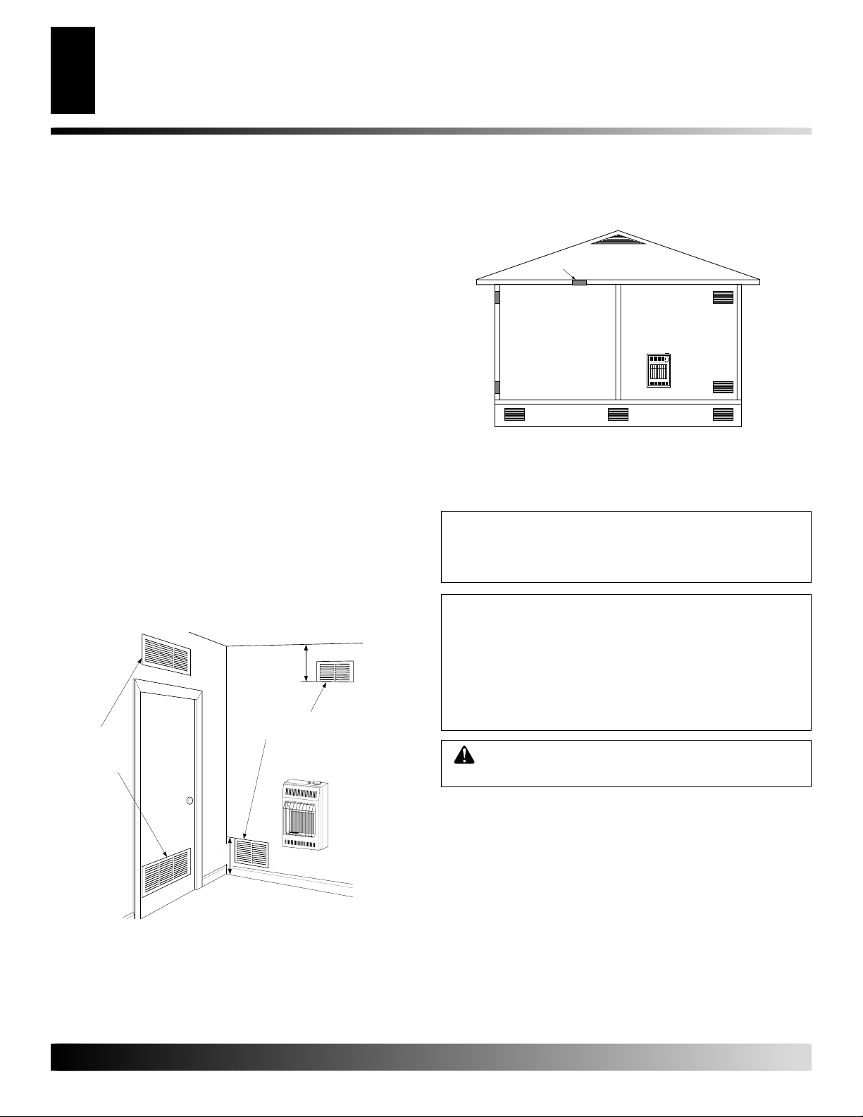
VENTILATION AIR
Ventilation Air From Inside Building
This fresh air would come from an adjoining unconfined space.
When ventilating to an adjoining unconfined space, you must
provide two permanent openings: one within 18" (45 cm) of the
ceiling and one within 18" (45 cm) of the floor on the wall
connecting the two spaces (see options 1 and 2, Figure 2). You can
also remove door into adjoining room (see option 3, Figure 2).
Follow CAN/CGA B149.1 Natural Gas Installation Code or CAN/
CGA B149.2 Propane Installation Code for required size of ventilation grills or ducts.
Ventilation Air From Outdoors
Provide extra fresh air by using ventilation grills or ducts. You must
provide two permanent openings: one within 18" (45 cm) of the
ceiling and one within 18" (45 cm) of the floor. Connect these items
directly to the outdoors or spaces open to the outdoors. These spaces
include attics and crawl spaces. Follow CAN/CGA B149.1 Natural
Gas Installation Code or CAN/CGA B149.2 Propane Installation
Code for required size of ventilation grills or ducts.
IMPORTANT:
attic if attic has a thermostat-controlled power vent. Heated air
entering the attic will activate the power vent.
Ventilation
Grills
into Adjoining
Room,
Option 1
Do not provide openings for inlet or outlet air into
18"
12"
(45 cm)
Ventilation Grills
Into Adjoining Room,
Or
Remove
Door into
Adjoining
Room,
Option 3
Option 2
Ventilated
Attic
Crawl Space
Ventilated
To Attic
To
Crawl
Space
Outlet
Air
Inlet
Air
Outlet
Air
Inlet Air
Figure 3 - Ventilation Air from Outdoors
INSTALLATION
Installation must conform with local codes or, in the
absence of local codes, with the current standard
CAN/CGA B149.1 Natural Gas Installation Code
CAN/CGA B149.2 Propane Installation Code
NOTICE: This heater is intended for use as supplemental heat. Use this heater along with your primary
heating system. Do not install this heater as your
primary heat source. If you have a central heating
system, you may run system’s circulating blower
while using heater. This will help circulate the heat
throughout the house. In the event of a power outage,
you can use this heater as your primary heat source.
WARNING: A qualified service person must in-
stall heater. Follow all local codes.
CHECK GAS TYPE
or
18"
12"
(45 cm)
Figure 2 - Ventilation Air from Inside Building
For more information, visit www.desatech.com
For more information, visit www.desatech.com
Use only the correct type of gas (natural or propane/LP). If your gas
supply is not the correct gas type, do not install heater. Call dealer
where you bought heater for proper type heater.
112157-01A
)
INSTALLATION
Continued
INSTALLATION
Installation Items
Locating Heater
7
7
INSTALLATION ITEMS
Before installing heater, make sure you have the items listed below.
• for propane/LP gas, external regulator (supplied by installer)
• piping (check local codes)
• sealant (resistant to propane/LP gas)
• equipment shutoff valve *
• ground joint union
• sediment trap
• tee joint
• pipe wrench
• for natural gas, test gauge connection*
* A CSA design-certified equipment shutoff valve with 1/8" NPT
tap is an acceptable alternative to test gauge connection. Purchase
the optional CSA design-certified equipment shutoff valve from
your dealer. See Accessories, page 29.
LOCATING HEATER
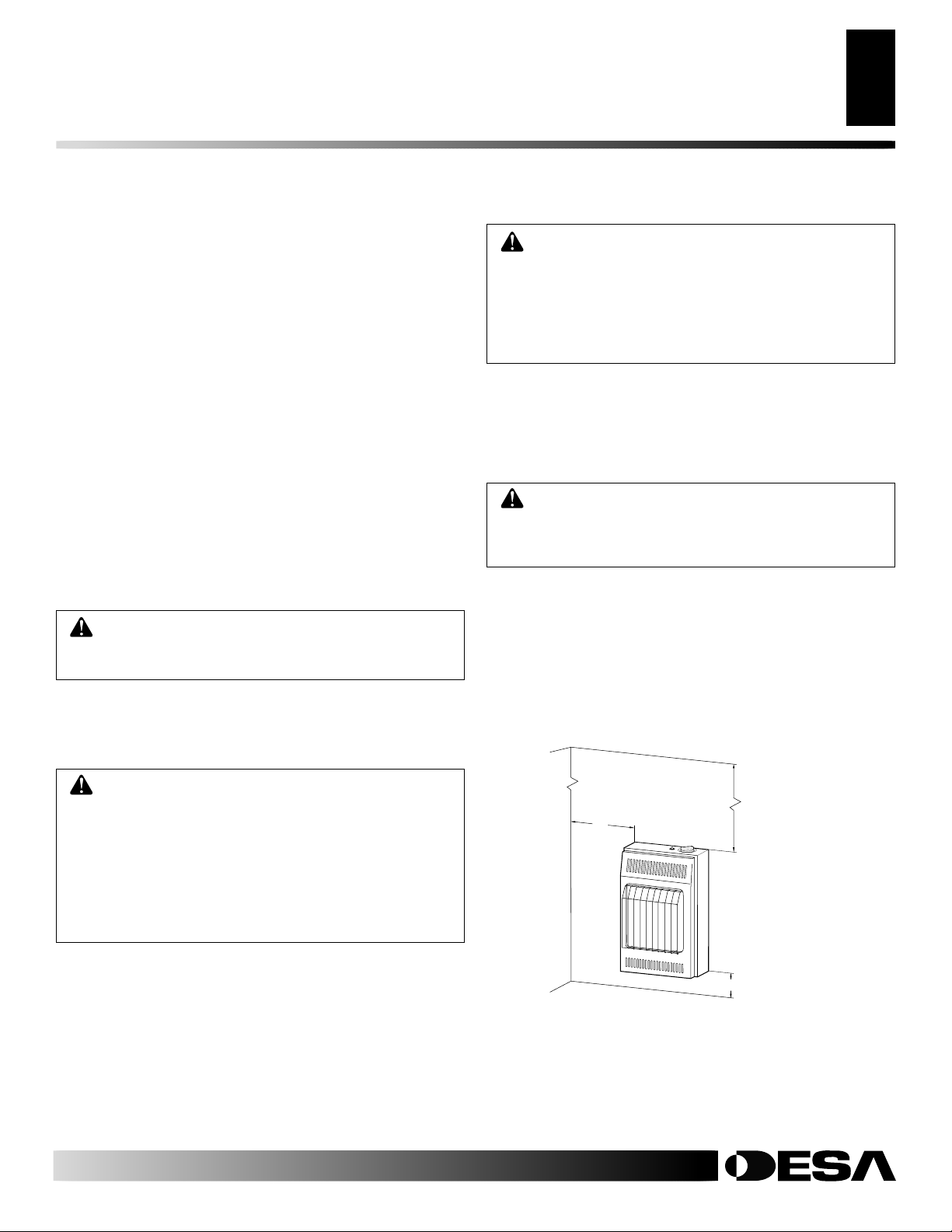
This heater is designed to be mounted on a wall.
WARNING: Maintain the minimum clearances
shown in Figure 4. If you can, provide greater clearances from floor, ceiling, and joining wall.
Models GCN20T and GCP20T only: You can locate heater on
floor, away from a wall. An optional floor mounting stand is needed.
Purchase the floor mounting stand from your dealer. See Accesso-
ries, page 29.
CAUTION: This heater creates warm air currents.
These currents move heat to wall surfaces next to
heater. Installing heater next to vinyl or cloth wall
coverings or operating heater where impurities (such
as but not limited to, tobacco smoke, aromatic candles,
cleaning fluids, oil or kerosene lamps, etc.) in the air
exist, may discolor walls or cause odors.
IMPORTANT:
Vent-free heaters add moisture to the air. Although
this is beneficial, installing heater in rooms without enough ventilation air may cause mildew to form from too much moisture. See
Air for Combustion and Ventilation, pages 4 through 6. If high
humidity is experienced, a dehumidifier may be used to help lower
the water vapor content in the air.
CAUTION: If you install the heater in a home garage
• heater pilot and burner must be at least 18 inches
(46 cm) above floor
• locate heater where moving vehicle will not hit it
For convenience and efficiency, install heater
• where there is easy access for operation, inspection, and service
• in coldest part of room
For 20,000 Btu/hr (5.9 kW) models, an optional fan kit is available
from your dealer. See Accessories, page 29. If planning to use fan,
locate heater near a grounded electrical outlet. Outlet must be
grounded in accordance with local codes, with the current Canadian
Electrical Code Part 1 CSA C22.1.
CEILING
WARNING: Never install the heater
• in a bedroom or bathroom
• in a recreational vehicle
• where curtains, furniture, clothing, or other flam-
mable objects are less than 36 inches (92 cm) from
the front, top, or sides of the heater
• as a fireplace insert
• in high traffic areas
• in windy or drafty areas
For more information, visit www.desatech.com
For more information, visit www.desatech.com
112157-01A
6"
(15.3 cm)
Minimum
From
Sides Of
Heater
Left
Side
Figure 4 - Mounting Clearances As Viewed From Front of Heater
36" (91.5 cm
Minimum
6,000 Btu/Hr
(1.8 kW)
Model Shown
Right
Side
Minimum To Top Surface
Of Carpeting, Tile Or Other
Combustible Material
3" (7.7 cm)
INSTALLATION
8
Thermostat Sensing Bulb (Thermostat Models Only)
Installing Heater To Wall 6,000 and 10,000 Btu/Hr Models (1.8 and 2.9 kW)
INSTALLATION
Continued
THERMOSTAT SENSING BULB
(Thermostat Models Only)
The thermostat sensing bulb has been placed inside the heater for
protection during shipping.
Locating Thermostat Sensing Bulb (for thermostat
applications)
1. Remove front panel of heater [for 10,000 Btu/Hr (2.9 KW) heater,
see Figure 11 page 9 or for 20,000 Btu/Hr (5.9 KW) heater see
Figure 14, page 10].
2. Locate thermostat sensing bulb just under burner assembly.
IMPORTANT:
Attach thermostat sensing bulb to back of heater for
proper operation.
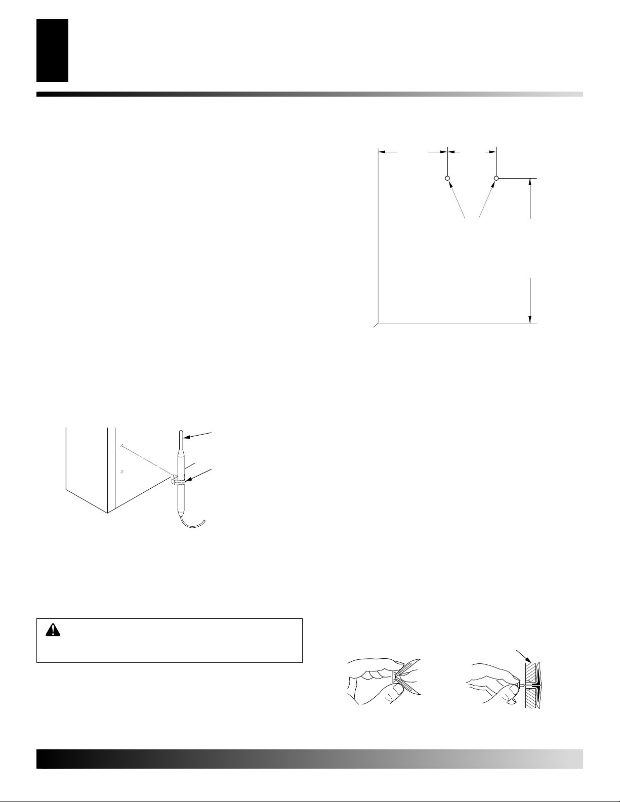
Attaching Thermostat Sensing Bulb
1. Remove thermostat sensing bulb from holders inside heater.
Route through slot opening in bottom of heater.
2. Place clamp on thermostat sensing bulb as shown in Figure 5.
Clamp is provided in hardware package.
3. Snap clamp into upper mounting hole as shown in Figure 5.
Mounting hole is located on lower left edge on back of heater.
Make sure the thermostat sensing bulb is pointing up.
Thermostat
Sensing Bulb
Clamp
Figure 5 - Attaching Thermostat Sensing Bulb
INSTALLING HEATER TO WALL 6,000 AND
10,000 BTU/HR MODELS (1.8 AND 2.9 KW)
Marking Screw Locations
1. Determine where you will locate heater.
WARNING: Maintain minimum clearances shown
in Figure 6. If you can, provide greater clearances
from floor and joining wall.
7
/8"
8
(22.5 cm)
Blue Flame
Minimum To
Maintain 6"
Clearance
From Wall
JOINING WALL
FLOOR
Figure 6 - Mounting Screw Locations
3
/4"
7
(19.7 cm)
Mounting
Screw
Locations
1
/4" (51.4 cm)
20
Minimum To
Maintain 3" (7.6
cm) Clearance
From Floor
Installing Two Mounting Screws
Note:
Wall anchors and mounting screws are in hardware package.
The hardware package is provided with heater.
Attaching to wall stud method
For attaching mounting screw to wall stud
1. Drill hole at marked location using 9/64" drill bit.
2. Insert mounting screw into wall stud.
3. Tighten screw until 1/16" (1.6 mm) space (thickness of penny)
is between screwhead and wall.
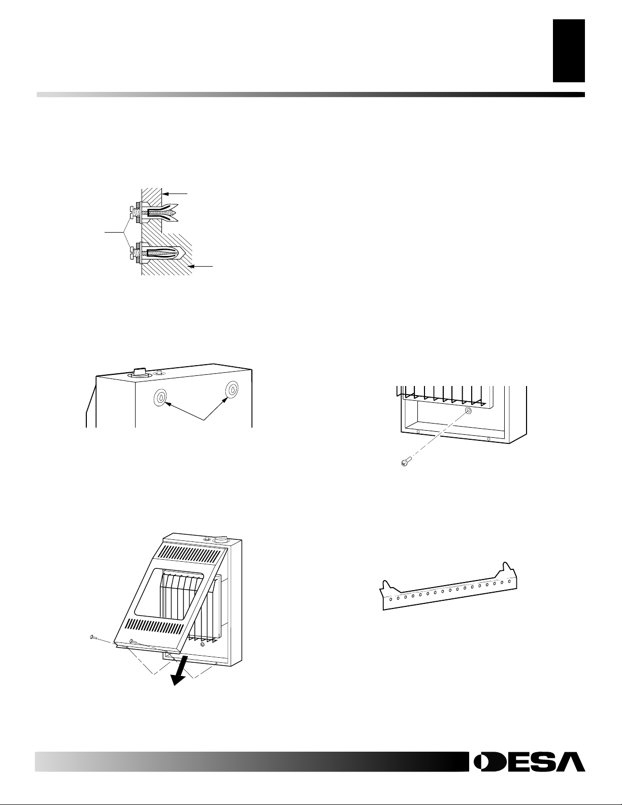
Attaching to wall anchor method
Follow instructions below to attach mounting screws to hollow walls
(wall areas between studs) or solid walls (concrete or masonry).
1. Drill holes at marked locations using 5/16" drill bit. For solid
walls (concrete or masonry), drill at least 1 1/4" (3.2 cm) deep.
2. Fold wall anchor (see Figure 7).
3. Insert wall anchor (wings first) into hole. Tap anchor flush
to wall.
4.
For thin walls [1/2" (1.27 cm ) or less], insert red key into wall
anchor. Push red key to “pop” open anchor wings (see Figure 8).
IMPORTANT:
(1.27 cm) thick] or solid walls, do not pop open wings.
Do not hammer key! For thick walls [over 1 /2"
Thin Walls (1/4" to 1/2" thick)
(1.6 to 1.2 cm)
2. Mark two mounting screw locations on wall (see Figure 6).
For more information, visit www.desatech.com
For more information, visit www.desatech.com
Figure 7 - Folding Anchor
Figure 8 - Popping Open Anchor
Wings For Thin Walls
112157-01A
INSTALLATION
Continued
Installing Heater To Wall 6,000 and 10,000 Btu/Hr Models (1.8 and 2.9 kW) (Cont.)
INSTALLATION
Installing Heater To Wall 20,000 Btu/Hr Models (5.9 kW)
9
9
5. Tighten two screws until 1/16" (1.6 mm) space (thickness of
penny) is between screwheads and wall (see Figure 9).
Thin or
Thick Wall
(thick wall
shown)
1/16"
Space
(1.6 mm)
Solid
Wall
Figure 9 - Tightening Anchors
Placing Heater On Mounting Screws
1. Locate two keyhole slots on back panel of heater (see Figure 10).
2. Place large openings of slots over screwheads. Slide heater
down until screws are in small portion of slots.
Keyhole Slots
Installing Bottom Mounting Screw
1. Locate bottom mounting hole. This hole is near bottom on back
panel of heater (see Figure 12).
2. Mark screw location on wall.
3. Remove heater from wall.
4. If installing bottom mounting screw into hollow or solid wall,
install wall anchor. Follow steps 1 through 5 under Attaching T o
Wall Anchor Method, page 10. If installing bottom mounting
screw into wall stud, drill hole at marked location using 9/64"
drill bit.
5. Replace heater on wall.
6. Insert bottom anchor screw through back panel into bottom
anchor or drilled hole (see Figure 12).
7. Tighten screw until heater is firmly secured to wall. Do not
over tighten.
Note:
Do not replace front panel at this time. Replace front
panel after making gas connections and checking for leaks (see
pages 11 and 12).
Figure 10 - Location Of Keyhole Slots On Back Panel Of Heater
Removing Front Panel Of Heater
1. Remove two screws near bottom corners of front panel.
2. Lift straight up on grill guard until it stops. Grill guard will slide
up about 1/4" (6 mm).
3. Pull bottom of front panel forward, then down.
Figure 11 - Removing Front Panel Of Heater
Figure 12 - Installing Bottom Mounting Screw
INSTALLING HEATER TO WALL
20,000 BTU/HR MODELS (5.9 KW)
Mounting Bracket
Locate mounting bracket in heater carton. Remove mounting bracket
from heater carton.
Figure 13 - Mounting Bracket
112157-01A
For more information, visit www.desatech.com
For more information, visit www.desatech.com
INSTALLATION
10
Installing Heater To Wall 20,000 Btu/Hr Models (5.9 kW) (Cont.)
INSTALLATION
Continued
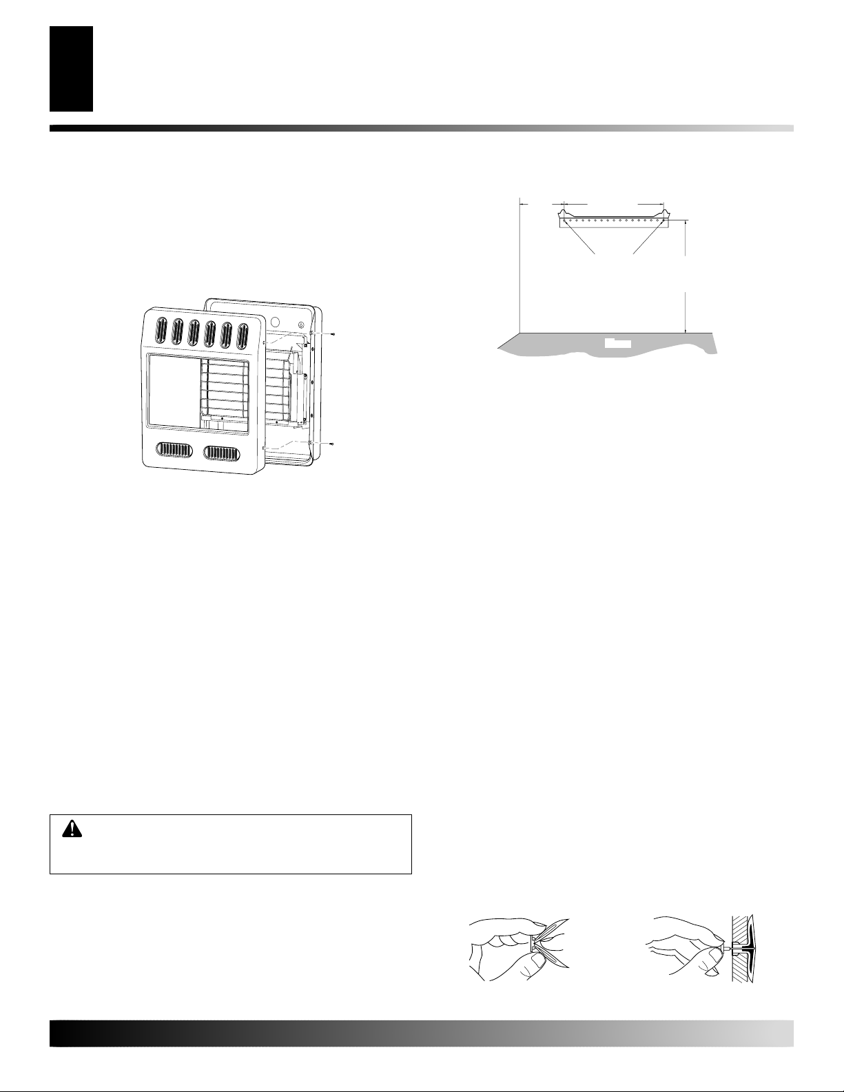
Removing Front Panel Of Heater (20,000 Btu/Hr
Models Only) (5.9 kW)
1. Remove the four painted screws, two on each side of front panel.
2. Pull bottom of front panel forward, then out.
3. Remove any remaining packaging materials.
8"
(20.3 cm)
Min.
Only Insert Mounting
Screws Through Last
Hole On Each End
Adjoining Wall
Figure 15 - Mounting Bracket Clearances
14"
(35.6 cm)
18 3/4"
(47.7 cm)
Min.
Floor
Attaching Mounting Bracket To Wall
Note:
Wall anchors, mounting screws, and spacers are in hardware
package. The hardware package is provided with heater.
Figure 14 - Removing Front Panel Of Heater
Methods For Attaching Mounting Bracket To Wall
Only use last hole on each end of mounting bracket to attach bracket
to wall. These two holes are 14 inches (35.5 cm) apart from their
centers. Attach mounting bracket to wall in one of two ways:
1. Attaching to wall stud
2. Attaching to wall anchor
Attaching to Wall Stud: This method provides the strongest hold.
Insert mounting screws through mounting bracket and into wall studs.
Attaching to Wall Anchor: This method allows you to attach
mounting bracket to hollow walls (wall areas between studs) or to
solid walls (concrete or masonry).
Decide which method better suits your needs. Either method will
provide a secure hold for the mounting bracket.
Marking Screw Locations
1. Tape mounting bracket to wall where heater will be located.
Make sure mounting bracket is level.
WARNING: Maintain minimum clearances shown
in Figure 15. If you can, provide greater clearances
from floor and joining wall.
2. Mark screw locations on wall (see Figure 15).
Note:
Only mark last hole on each end of mounting bracket.
Insert mounting screws through these holes only.
3. Remove tape and mounting bracket from wall.
Attaching To Wall Stud Method
For attaching mounting bracket to wall studs
1. Drill holes at marked locations using 9/64" drill bit.
2. Place mounting bracket onto wall. Line up last hole on each
end of bracket with holes drilled in wall.
3. Insert mounting screws through bracket and into wall studs.
4. Tighten screws until mounting bracket is firmly fastened to
wall studs.
Attaching To Wall Anchor Method
For attaching mounting bracket to hollow walls (wall areas between studs) or solid walls (concrete or masonry)
1. Drill holes at marked locations using 5/16" drill bit. For solid
walls (concrete or masonry), drill at least 1" (2.5 cm) deep.
2. Fold wall anchor as shown in Figure 16.
3. Insert wall anchor (wings first) into hole. Tap anchor flush
to wall.
4. For thin walls [1/2" (1.27 cm) or less ], insert red key into wall
anchor. Push red key to “pop” open anchor wings.
IMPORTANT:
Do not hammer key!
For thick walls [over 1/2" (1.27 cm) thick] or solid walls, do
not pop open wings.
5. Place mounting bracket onto wall. Line up last hole on each
end of bracket with wall anchors.
6. Insert mounting screws through bracket and into wall anchors.
7. Tighten screws until mounting bracket is firmly fastened to wall.
Figure 16 - Folding Anchor
For more information, visit www.desatech.com
For more information, visit www.desatech.com
Figure 17- Popping Open
Anchor Wings For Thin Walls
112157-01A
INSTALLATION
Continued
Installing Heater To Wall 20,000 Btu/Hr Models (5.9 kW) (Cont.)
INSTALLATION
Mounting Heater To Floor With Optional Floor Kit [20,000 Btu/Hr (5.9 kW) Only]
11
11
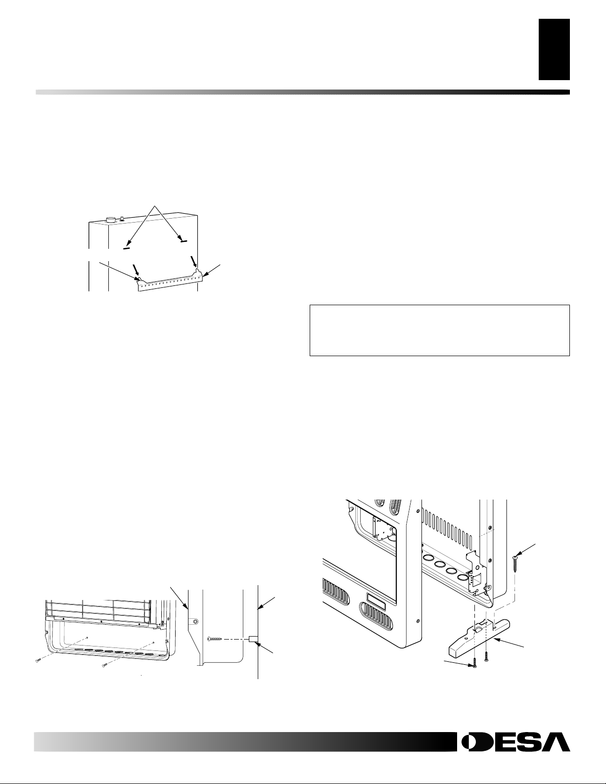
Placing Heater On Mounting Bracket
1. Locate two horizontal slots on back panel of heater.
2. Place heater onto mounting bracket. Slide horizontal slots onto
stand-out tabs on mounting bracket.
Horizontal Slots
Stand-Out Tab
Figure 18 - Mounting Heater Onto Mounting Bracket
Mounting Bracket
(attached to wall)
Installing Bottom Mounting Screws
1. Locate two bottom mounting holes. These holes are near bottom on back panel of heater (see Figure 19).
2. Mark screw locations on wall.
3. Remove heater from mounting bracket.
4. If installing bottom mounting screws into hollow or solid wall,
install wall anchors. Follow steps 1 through 4 under Attaching T o
W all Anc hor Method, page 10.
If installing bottom mounting screw into wall stud, drill holes
at marked locations using 9/64" drill bit.
5. Replace heater onto mounting bracket.
6. Place spacers between bottom mounting holes and wall anchor
or drilled hole.
7. Hold spacer in place with one hand. With other hand, insert
mounting screw through bottom mounting hole and spacer.
Place tip of screw in opening of wall anchor or drilled hole.
8. Tighten both screws until heater is firmly secured to wall. Do
not over tighten.
Note:
Do not replace front panel at this time. Replace front
panel after making gas connections and checking for leaks (see
pages 11 and 12).
Heater
Wall
MOUNTING HEATER TO FLOOR WITH OPTIONAL
FLOOR KIT [20,000 BTU/HR (5.9 KW) ONLY]
Mounting Base Feet to Heater
1. Lay heater cabinet on its back on a table with the heater bottom overhanging the table edge.
2. Align holes in base foot with mounting holes on bottom of
cabinet (see Figure 20).
3. Secure base foot to heater using sheet metal screws.
4. Repeat for other side.
Mounting Base Feet to Floor (Where required by
local code)
If heater is being installed directly on carpeting, tile or
other combustible material (other than wood flooring),
the heater shall be installed on a metal or wood panel
extending the full width and depth of the appliance.
1. Remove front cover (see Removing Front Panel of Heater,
page 10).
2. Position heater with base feet in desired location. Mark holes
for drilling. Remove heater with base.
3. If mounting base to a wood floor, drill 1/8 inch diameter hole,
3/4 inch (2 cm) deep. (Do not use anchors in wood floors).
If mounting base to a concrete floor, drill with 1/4 inch diameter concrete drill bit, 13/8 inches (3.5 cm) into floor. Insert
anchors completely into holes.
4. Reposition heater with base feet over holes. Secure base to floor
with wood screws. See Figure 20.
Wood
Screw
Front View
Figure 19 - Installing Bottom Mounting Screws
For more information, visit www.desatech.com
For more information, visit www.desatech.com
112157-01A
Side View
Spacer
Base Foot
Sheet Metal Screw
Figure 20 - Installing Base Feet (Heater may vary from illustration)
INSTALLATION
12
Connecting To Gas Supply
INSTALLATION
Continued
CONNECTING TO GAS SUPPLY
WARNING: This appliance requires a 3/8" NPT
(National Pipe Thread) inlet connection to the pressure regulator.
WARNING: A qualified service person must connect heater to gas supply. Follow all local codes.
WARNING: For natural gas, never connect heater to
private (non-utility) gas wells. This gas is commonly
known as wellhead gas.
IMPORTANT
connecting heater to gas line. Gas line pressure must be no greater than
10.5 inches (26.6 cm) of water. If gas line pressure is higher, heater
regulator damage could occur.
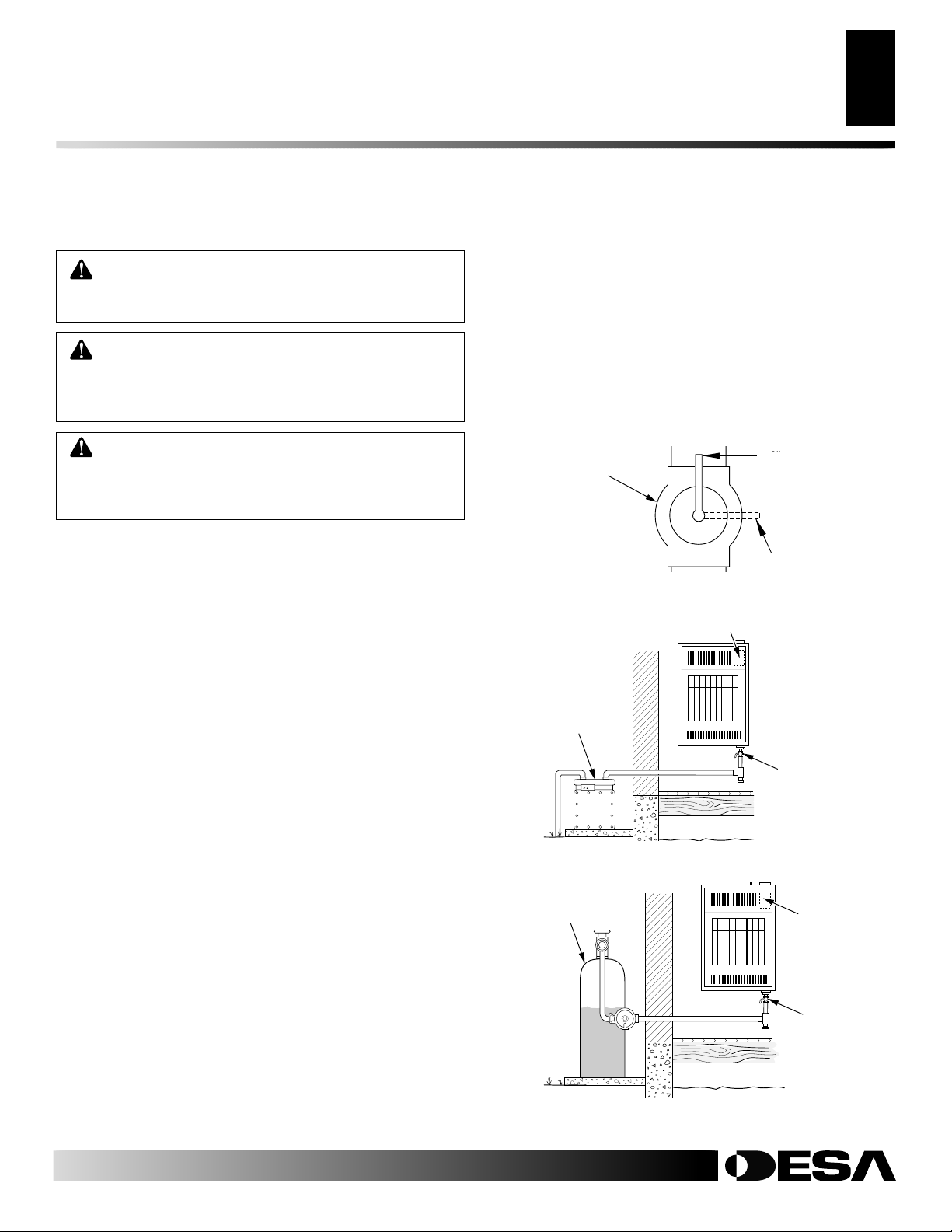
CAUTION: For propane/LP gas, never connect
heater directly to the propane/LP supply. This heater
requires an external regulator (not supplied). Install
the external regulator between the heater and propane/LP supply.
For propane/LP gas, the installer must supply an external regulator. The
external regulator will reduce incoming gas pressure. You must reduce
incoming gas pressure to between 11 and 14 inches (28 and 35.5 cm)
of water. If you do not reduce incoming gas pressure, heater regulator
damage could occur. Install external regulator with the vent pointing
down as shown in Figure 21. Pointing the vent down protects it from
freezing rain or sleet.
CAUTION: Use only new, black iron or steel pipe.
Internally-tinned copper tubing may be used in certain areas. Check your local codes. Use pipe of large
enough diameter to allow proper gas volume to heater.
If pipe is too small, undue loss of volume will occur.
Typical inlet pipe diameter for 20,000 btu/hr (5.9 kW) models - 3/8"
or greater.
: For natural gas, check gas line pressure before
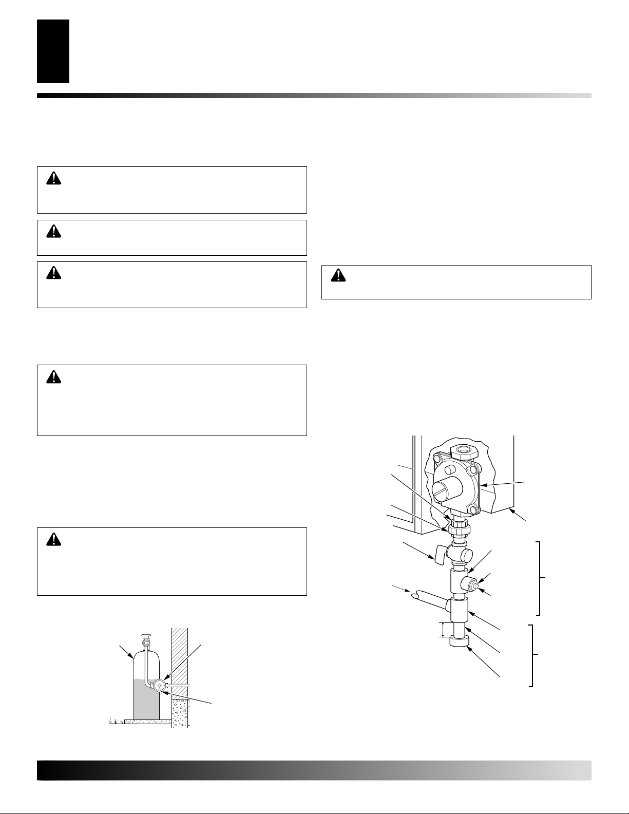
Propane/LP
Supply Tank
External Regulator
Installation must include equipment shutoff valve, union, and plugged
1/8" NPT tap. Locate NPT tap within reach for test gauge hook up.
NPT tap must be upstream from heater (see Figure 22).
IMPORTANT:
Install an equipment shutoff valve in an accessible
location. The equipment shutoff valve is for turning on or shutting
off the gas to the appliance.
Apply pipe joint sealant lightly to male NPT threads. This will
prevent excess sealant from going into pipe. Excess sealant in pipe
could result in clogged heater valves.
WARNING: Use pipe joint sealant that is resistant
to liquid petroleum (LP) gas.
We recommend that you install sediment trap in supply line as
shown in Figure 22. Locate sediment trap where it is within reach for
cleaning. Install in piping system between fuel supply and heater.
Locate sediment trap where trapped matter is not likely to freeze. A
sediment trap traps moisture and contaminants. This keeps them
from going into heater controls. If sediment trap is not installed or
is installed wrong, heater may not run properly.
IMPORTANT:
Hold pressure regulator with wrench when connecting it to gas piping and/or fittings. Do not over tighten pipe
connection to regulator. The regulator body could be damaged.
3/8" NPT
Pipe Nipple
Ground
Joint Union
Equipment
Shutoff Valve*
Natural Gas
From Gas Meter
[
6/10,000 Btu/Hr (1.8/2.9 kW)
4" (10 cm) W.C. to
10.5" (26.7 cm) W.C.
Pressure]
20,000 Btu/Hr (5.9 kW)
5" (12.7 cm) W.C. to 10.5"
(26.7 cm) W.C. Pressure]
Propane/LP
From External Regulator
(11" (27.9 cm) W.C. to
14" (35.6 cm) W.C. Pressure)
3"
7.7 cm)
Minimum
Tee Joint
Reducer
Bushing to
1/8" NPT
1/8" NPT
Plug Tap
Tee
Joint
Pipe
Nipple
Cap
Pressure
Regulator
Heater
Cabinet
Test
Gauge
Connection*
Sediment
Trap
Vent Pointing Down
Figure 21 - External Regulator With Vent Pointing Down
(Propane/LP Systems Only)
For more information, visit www.desatech.com
For more information, visit www.desatech.com
Figure 22 - Gas Connection
* A CSA design-certified equipment shutoff valve with 1/8" NPT
tap is an acceptable alternative to test gauge connection. Purchase
the optional CSA design-certified equipment shutoff valve from
your dealer. See Accessories, page 29.
112157-01A
ON
POSITIO
OF
POSI
INSTALLATION
Continued
Checking Gas Connections
INSTALLATION
13
13
CHECKING GAS CONNECTIONS
WARNING: Test all gas piping and connections
for leaks after installing or servicing. Correct all leaks
at once.
WARNING: Never use an open flame to check for
a leak. Apply a noncorrosive leak detection fluid to all
joints. Bubbles forming show a leak. Correct all leaks
at once.
CAUTION: For propane/LP gas, make sure external regulator has been installed between propane/LP
supply and heater. See guidelines under
to Gas Supply
, page 12.
Pressure Testing Gas Supply Piping System
Test Pressures In Excess Of 1/2 PSIG (3.5 kPa)
1. Disconnect appliance with its appliance main gas valve (control valve) and equipment shutoff valve from gas supply piping system. Pressures in excess of 1/2 psig (3.5 kPa) will damage heater regulator.
2. Cap off open end of gas pipe where equipment shutoff valve
was connected.
3. Pressurize supply piping system by either opening propane/LP
supply tank valve for propane/LP gas or opening main gas valve
located on or near gas meter for natural gas, or using compressed air.
4. Check all joints of gas supply piping system. Apply a noncorrosive
leak detection fluid to all joints. Bubbles forming show a leak.
5. Correct all leaks at once.
6. Reconnect heater and equipment shutoff valve to gas supply.
Check reconnected fittings for leaks.
Test Pressures Equal To or Less Than 1/2 PSIG (3.5 kPa)
1. Close equipment shutoff valve (see Figure 23).
2. Pressurize supply piping system by either opening propane/
LP supply tank valve for propane/LP gas or opening main gas
valve located on or near gas meter for natural gas, or using
compressed air.
3. Check all joints from gas meter for natural gas (see Figure 24)
or propane/LP supply tank for propane/LP gas, to equipment
shutoff valve (see Figure 25). Apply a noncorrosive leak detection fluid to all joints. Bubbles forming show a leak.
4. Correct all leaks at once.
Connecting
2. Open main gas valve located on or near gas meter for natural
gas or open propane/LP supply tank valve.
3. Make sure control knob of heater is in the OFF position.
4. Check all joints from equipment shutoff valve to control valve
(see Fig ures 24 and 25 ). Apply a noncorrosive leak detection
fluid to all joints. Bubbles forming show a leak.
5. Correct all leaks at once.
6. Light heater (see Operating Heater pages 14 and 15). Check
the rest of the internal joints for leaks.
7. Turn off heater (see To Turn Off Gas to Appliance, page 15).
8. Replace front panel.
Equipment
Shutoff Valve
Figure 23 - Equipment Shutoff Valve
Control Valve Location
Gas
Meter
Figure 24 - Checking Gas Joints for Natural Gas [6, 000 Btu/Hr
Model (1.8 kW) Shown]
Propane/LP
Supply Tank
Open
Closed
Equipment
Shutoff Valve
Control
Valve Location
Equipment
Shutoff Valve
Pressure Testing Heater Gas Connections
1. Open equipment shutoff valve (see Figure 23).
112157-01A
For more information, visit www.desatech.com
For more information, visit www.desatech.com
Figure 25 - Checking Gas Joints for Propane/LP Gas [6,000
Btu/Hr Model (1.8 kW) Shown]
OPERATING HEATER
14
For Your Safety Read Before Lighting
Lighting Instructions
OPERATING HEATER
FOR YOUR SAFETY READ
BEFORE LIGHTING
WARNING: If you do not follow these instructions
exactly, a fire or explosion may result causing property damage, personal injury or loss of life.
A. This appliance has a pilot which must be lighted by hand.
When lighting the pilot, follow these instructions exactly.
B. BEFORE LIGHTING smell all around the appliance area
for gas. Be sure to smell next to the floor because some gas
is heavier than air and will settle on the floor.
WHAT TO DO IF YOU SMELL GAS
• Do not try to light any appliance.
• Do not touch any electric switch; do not use any phone in
your building.
• Immediately call your gas supplier from a neighbor’s
phone. Follow the gas supplier’s instructions.
• If you cannot reach your gas supplier, call the fire department.
C. Use only your hand to push in or turn the gas control knob.
Never use tools. If the knob will not push in or turn by
hand, don’t try to repair it, call a qualified service technician or gas supplier. Force or attempted r epair may result
in a fire or explosion.
D. Do not use this appliance if any part has been under water.
Immediately call a qualified service technician to inspect the
appliance and to replace any part of the control system and
any gas control which has been under water.
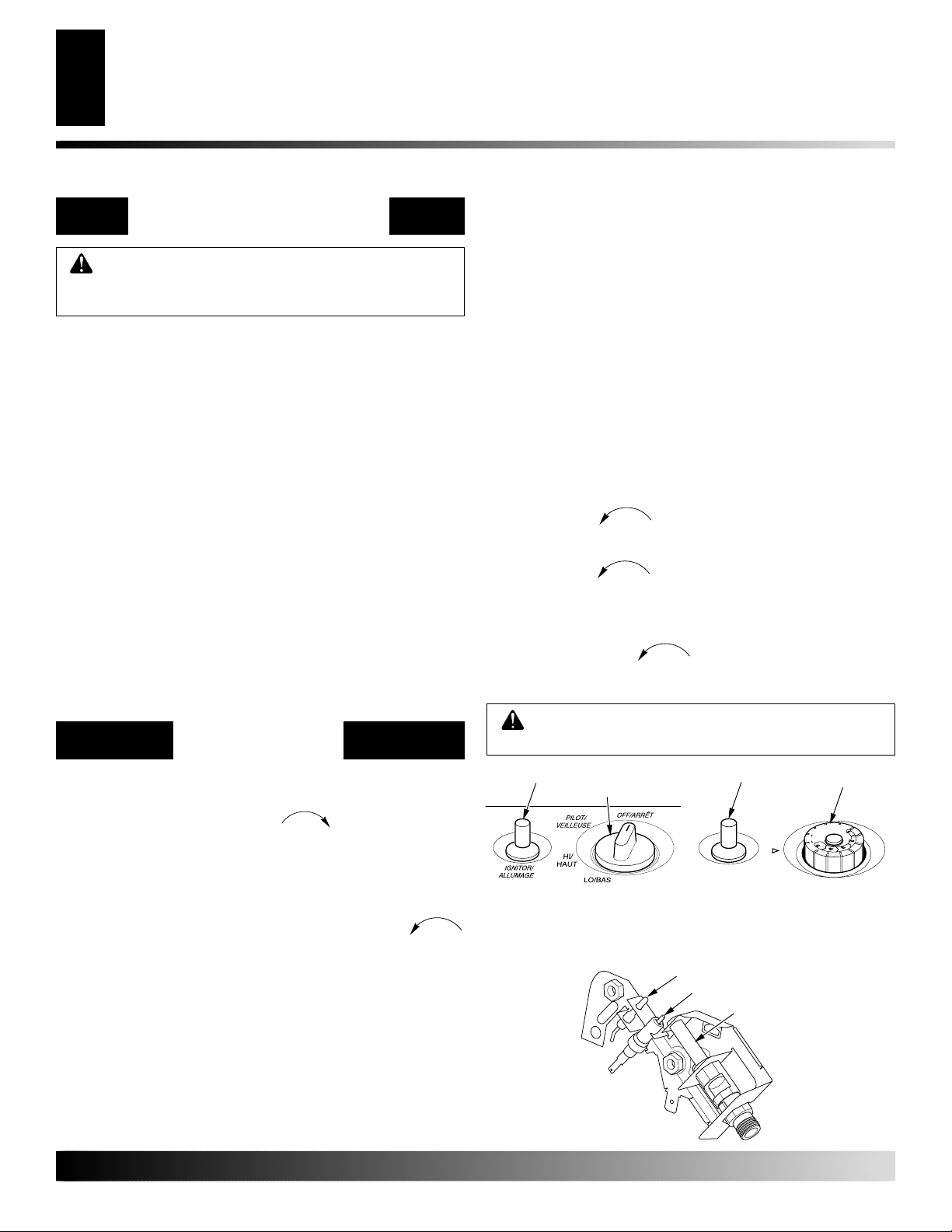
LIGHTING
INSTRUCTIONS
1. STOP! Read the safety information above.
2. Make sure equipment shutoff valve is fully open.
3. Turn control knob clockwise
(see Figure 26 or 27).
4. Wait five (5) minutes to clear out any gas. Then smell for
gas, including near the floor. If you smell gas, STOP! Follow “B” in the safety information, abov e. If you don’t smell
gas, go to the next step.
5. Press in control knob and turn counterclockwise
to the PILOT position. Keep control knob pressed in for
five (5) seconds (see Figure 26 or 27).
Note:
You may be running this heater for the first time
after hooking up to gas supply . If so, the control knob may
need to be pressed in for 30 seconds or more. This will allow air to bleed from the gas system.
• If control knob does not pop up when released, contact a
qualified service person or gas supplier for repairs.
to the OFF position
Clockwise
C-clockwise
6. With control knob pressed in, push down and release ignitor button. This will light pilot. The pilot is attached to the
front of burner. The pilot can be seen through the glass panel.
If needed, keep pressing ignitor button until pilot lights.
Note:
If pilot does not stay lit, refer to Troubleshooting,
pages 18 through 20. Also contact a qualified service person or gas supplier for repairs. Until r epairs are made, light
pilot with a match. To light pilot with amatch, see Manual
Lighting Procedure, page 15.
7. Keep control knob pressed in for 30 seconds after lighting
pilot. After 30 seconds, release control knob.
• If control knob does not pop up when released, contact a
qualified service person or gas supplier for repairs.
Note:
If pilot goes out, repeat steps 3 through 7. Thermostat model heaters have a safety interlock system. W ait one
(1) minute before lighting pilot again.
8. Manual Controlled Models Only T urn control knob coun-
terclockwise
C-clockwise
to the HI position. The main burner
should light. Set control knob to HI or LO. To turn control
knob from HI to LO, press in the control knob and turn counterclockwise
Note:
Both HI and LO are locked positions. Y ou must pr ess
C-clockwise
.
in control knob before turning it from these positions.
9. Thermostat Controlled Models Only T urn control knob
counterclockwise
C-clockwise
to desired heating level. The
main burner should light. Set control knob to any heat le vel
between 1 and 5.
CAUTION: Do not try to adjust heating levels by
using the equipment shutoff valve.
Ignitor Button
Control Knob
Figure 26 - Control Knob In
The OFF Position (Manual
Controlled Models)
Ignitor Button
Control Knob
T
O
L
I
P
F
F
O
Figure 27 - Control Knob In
The OFF Position (Thermostat
Controlled Models)
Thermocouple
Ignitor Electrode
Pilot Burner
Figure 28 - Pilot
For more information, visit www.desatech.com
For more information, visit www.desatech.com
112157-01A
To Turn Off Gas To Appliance
OPERATING HEATER
Thermostat Control Operation (Thermostat Models Only)
Manual Lighting Procedure
INSPECTING BURNER
Pilot Flame Pattern
Burner Flame Pattern
15
15
OPERATING HEATER
Continued
TO TURN OFF GAS
TO APPLIANCE
Shutting Off Heater
1. Press in and turn control knob clockwise
position.
2. Turn off all electric power to the appliance if service is to
be performed.
Shutting Off Burner Only (pilot stays lit)
Turn control knob clockwise
to the PILOT position.
Clockwise
THERMOSTAT CONTROL
OPERATION (THERMOSTAT
MODELS ONLY)
The thermostatic control used on these models differs from
standard thermostats. Standard thermostats simply turn on and
off the burner. The thermostat used on this heater senses the
room temperature. The thermostat adjusts the amount of gas
flow to the burner. This increases or decreases the burner flame
height. At times the room may exceed the set temperature. If so,
the burner will shut off. The burner will cycle back on when room
temperature drops below the set temperature. The control knob
can be set to any heat level between 1 and 5.
Note:
The thermostat sensing bulb measures the temperature of
air near the heater cabinet. This may not always agree with room
temperature (depending on housing construction, installation
location, room size, open air temperatures, etc.). Frequent use of
your heater will let you determine your own comfort levels.
MANUAL LIGHTING
PROCEDURE
1. Remove front panel [for 6,000 (1.8 kW) and 10,000 (2.9 kW)
Btu/Hr heater see Figure 11, page 9, for 20,000 Btu/Hr (5.9
kW) heater, see Figure 14 page 10].
2. Follow steps 1 through 5 under Lighting Instructions,
page 14.
3. With control knob pressed in, strik e match. Hold match to
pilot until pilot lights.
4. Keep control knob pressed in for 30 seconds after pilot is
lit. After 30 seconds, release control knob. Follow step 8
under Lighting Instructions, page 14.
5. Replace front panel.
Clockwise
to the OFF
INSPECTING BURNER
Check pilot flame pattern and burner flame pattern often.
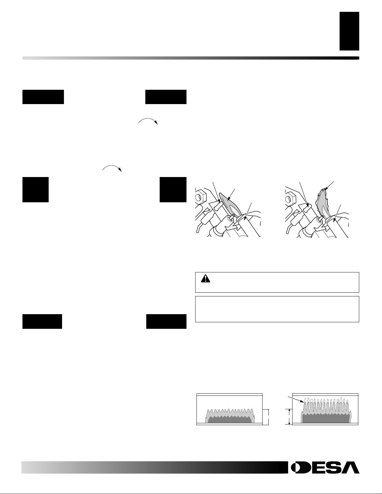
PILOT FLAME PATTERN
Figure 29 shows a correct pilot flame pattern. Figure 30 shows an
incorrect pilot flame pattern. The incorrect pilot flame is not
touching the thermocouple. This will cause the thermocouple to
cool. When the thermocouple cools, the heater will shut down.
If pilot flame pattern is incorrect, as shown in Figure 30
• turn heater off (see To Turn Off Gas to Appliance, column 1)
• see Troubleshooting, pages 18 through 20
Note:
The pilot flame on natural gas units will have a slight curve,
but flame should be blue and have no yellow or orange color.
Thermocouple
Blue Flame
Pilot Burner
Figure 29 - Correct Pilot
Flame Pattern
BURNER FLAME PATTERN
WARNING: If yellow tipping occurs, your heater
could produce increased levels of carbon monoxide.
NOTICE: Do not mistake orange flames with yellow
tipping. Dust or other fine particles enter the heater
and burn causing brief patches of orange flame.
Figure 31 shows a correct burner flame pattern. Figure 32 shows an
incorrect burner flame pattern. The incorrect burner flame pattern
shows yellow tipping of the flame. It also shows the flame higher
than 1/2 the glass panel height.
If burner flame pattern is incorrect, as shown in Figure 32
• turn heater off (see To Turn Off Gas to Appliance, column 1)
• see Troubleshooting, pages 18 through 20
Thermocouple
Figure 30 - Incorrect Pilot Flame
Pattern
Yellow
Tipping
1/2 GLASS HEIGHT
Yellow Flame
Pilot
Burner
112157-01A
(Models GCN6 and GCP6 will be
lower due to lower input rating)
Figure 31 - Correct Burner
Flame Pattern
For more information, visit www.desatech.com
For more information, visit www.desatech.com
Figure 32 - Incorrect Burner
Flame Pattern
CLEANING AND MAINTENANCE
16
ODS/Pilot and Burner Orifice
Burner Pilot Air Inlet Hole
Cabinet
CLEANING AND
MAINTENANCE
WARNING: Turn off heater and let cool before
cleaning.
CAUTION: You must keep control areas, burner,
and circulating air passageways of heater clean. Inspect these areas of heater before each use. Have
heater inspected yearly by a qualified service person.
Heater may need more frequent cleaning due to excessive lint from carpeting, bedding material, pet hair, etc.
WARNING: Failure to keep the primary air
opening(s) of the burner(s) clean may result in sooting and property damage.
ODS/PILOT AND BURNER ORIFICE
• Use a vacuum cleaner, pressurized air, or small, soft bristled
brush to clean.
BURNER PILOT AIR INLET HOLE
The primary air inlet holes allow the proper amount of air to mix with
the gas. This provides a clean burning flame. Keep these holes clear
of dust, dirt, lint, and pet hair. Clean these air inlet holes prior to each
heating season. Blocked air holes will create soot. We recommend
that you clean the unit every three months during operation and have
fireplace inspected yearly by a qualified service person.
We also recommend that you keep the burner tube and pilot
assembly clean and free of dust and dirt. To clean these parts we
recommend using compressed air no greater than 30 PSI (207 kPa).
Your local computer store, hardware store, or home center may
carry compressed air in a can. You can use a vacuum cleaner in the
blow position. If using compressed air in a can, please follow the
directions on the can. If you don't follow directions on the can, you
could damage the pilot assembly.
1. Shut off the unit, including the pilot. Allow the unit to cool for
at least thirty minutes.
2. Inspect burner, pilot for dust and dirt.
3. Blow air through the ports/slots and holes in the burner.
4. Never insert objects into the pilot tube.
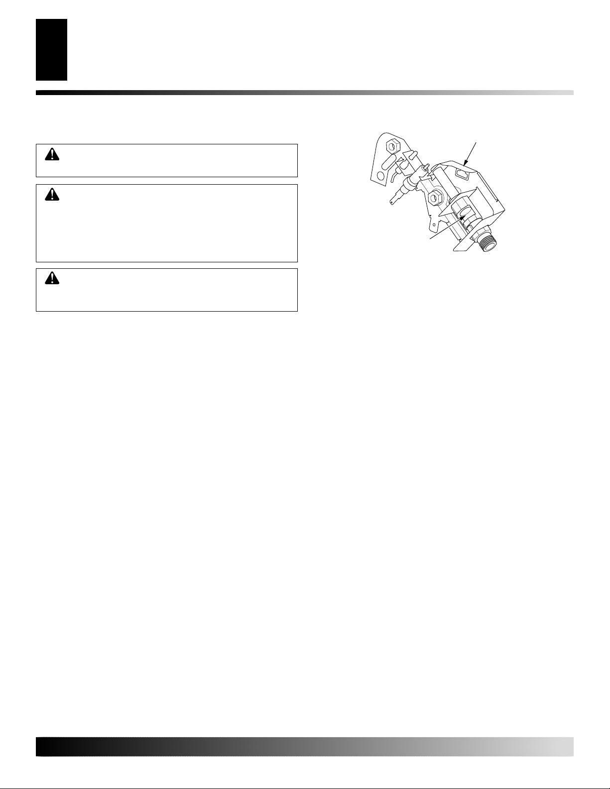
Clean the pilot assembly also. A yellow tip on the pilot flame
indicates dust and dirt in the pilot assembly. There is a small pilot
air inlet hole about two inches from where the pilot flame comes out
of the pilot assembly (see Figure 33). With the unit off, lightly blow
air through the air inlet hole. You may blow through a drinking straw
if compressed air is not available.
Pilot Assembly
Pilot Air Inlet
Figure 33 - Pilot Inlet Air Hole
CABINET
Air Passageways
• Use a vacuum cleaner or pressurized air to clean.
Exterior
• Use a soft cloth dampened with a mild soap and water mixture.
Wipe the cabinet to remove dust.
For more information, visit www.desatech.com
For more information, visit www.desatech.com
112157-01A
TROUBLESHOOTING
Note:
For additional help, visit DESA’s
technical service web site at
www.desatech.com.
Note:
All troubleshooting items are listed in
order of operation.
WARNING: Turn off heater
and let cool before servicing. Only
a qualified service person should
service and repair heater.
TROUBLESHOOTING
CAUTION: Never use a wire,
needle, or similar object to clean
ODS/pilot. This can damage ODS/
pilot unit.
17
17
OBSERVED PROBLEM
When ignitor button is pressed, there is no
spark at ODS/pilot
When ignitor button is pressed, there is
spark at ODS/pilot but no ignition
ODS/pilot lights but flame goes out when
control knob is released
POSSIBLE CAUSE
1. Ignitor electrode positioned wrong
2. Ignitor electrode broken
3. Ignitor electrode not connected to ignitor cable
4. Ignitor cable pinched or wet
5. Broken ignitor cable
6. Bad piezo ignitor
1. Gas supply turned off or equipment
shutoff valve closed
2. Control knob not in PILOT position
3. Control knob not pressed in while in
PILOT position
4. Air in gas lines when installed
5. Depleted gas supply (propane/LP only)
6. ODS/pilot is clogged
7. Gas regulator setting is not correct
1. Control knob not fully pressed in
2. Control knob not pressed in long enough
3. Safety interlock system has been
triggered
4. Equipment shutoff valve not fully open
5. Thermocouple connection loose at control valve
6. Pilot flame not touching thermocouple,
which allows thermocouple to cool,
causing pilot flame to go out. This problem could be caused by one or both of
the following:
A) Low gas pressure
B) Dirty or partially clogged ODS/pilot
7. Thermocouple damaged
8. Control valve damaged
REMEDY
1. Replace pilot assembly
2. Replace pilot assembly
3. Reconnect ignitor cable
4. Free ignitor cable if pinched by any
metal or tubing. Keep ignitor cable dry
5. Replace ignitor cable
6. Replace piezo ignitor
1. Turn on gas supply or open equipment
shutoff valve
2. Turn control knob to PILOT position
3. Press in control knob while in PILOT
position
4. Continue holding down control knob.
Repeat igniting operation until air is removed
5. Contact local propane/LP gas company
6. Clean ODS/pilot (see Cleaning and
Maintenance, page 16) or replace ODS/
pilot assembly
7. Replace gas regulator
1. Press in control knob fully
2. After ODS/pilot lights, keep control
knob pressed in 30 seconds
3. Wait one minute for safety interlock system to reset. Repeat ignition operation
4. Fully open equipment shutoff valve
5. Hand tighten until snug, then tighten 1/4
turn more
6. A) Contact local natural or propane/LP
gas company
B) Clean ODS/pilot (see Cleaning and
Maintenance, page 16) or replace ODS/
pilot assembly
7. Replace pilot assembly
8. Replace control valve
112157-01A
For more information, visit www.desatech.com
For more information, visit www.desatech.com

TROUBLESHOOTING
18
TROUBLESHOOTING
Continued
OBSERVED PROBLEM
Burner does not light after ODS/pilot is lit
Delayed ignition of burner
Burner backfiring during combustion
Yellow flame during burner combustion
POSSIBLE CAUSE
1. Burner orifice is clogged
2. Inlet gas pressure is too low
1. Manifold pressure is too low
2. Burner orifice is clogged
1. Burner orifice is clogged or damaged
2. Burner damaged
3. Gas regulator defective
1. Not enough air
2. Gas regulator defective
3. Clogged or dirty burner
REMEDY
1. Clean burner orifice (see Cleaning and
Maintenance, page 16) or replace burner
orifice
2. Contact local natural or propane/LP gas
company
1. Contact local natural or propane/LP gas
company
2. Clean burner orifice (see Cleaning and
Maintenance, page 16) or replace burner
orifice
1. Clean burner orifice (see Cleaning and
Maintenance, page 16) or replace burner
orifice
2. Replace burner
3. Replace gas regulator
1. Check burner for dirt and debris. If
found, clean burner (see Cleaning and
Maintenance, page 16)
2. Replace gas regulator
3. Clean burner (see Cleaning and Main-
tenance, page 16)
Slight smoke or odor during initial operation
Heater produces a whistling noise when
burner is lit
Heater produces a clicking/ticking noise
just after burner is lit or shut off
1. Residues from manufacturing processes
1. Turning control knob to HI position
when burner is cold
2. Air in gas line
3. Air passageways on heater blocked
4. Dirty or partially clogged burner orifice
1. Metal expanding while heating or contracting while cooling
1. Problem will stop after a few hours of
operation
1. Turn control knob to LO position and
let warm up for a minute
2. Operate burner until air is removed from
line. Have gas checked by local natural
or propane/LP gas company
3. Observe minimum installation clearances (see Figure 4, page 7)
4. Clean burner (see Cleaning and Mainte-
nance, page 16) or replace burner orifice
1. This is common with most heaters. If
noise is excessive, contact qualified service person
For more information, visit www.desatech.com
For more information, visit www.desatech.com
112157-01A

TROUBLESHOOTING
Continued
WARNING: If you smell gas
• Shut off gas supply.
• Do not try to light any appliance.
• Do not touch any electrical switch; do not use any phone in your
building.
• Immediately call your gas supplier from a neighbor’s phone. Follow the
gas supplier’s instructions.
• If you cannot reach your gas supplier, call the fire department.
TROUBLESHOOTING
19
19
IMPORTANT:
supplies, paint, paint remover, cigarette smoke, cements and glues, new carpet or textiles,
etc., create fumes. These fumes may mix with combustion air and create odors.
Operating heater where impurities in air exist may create odors. Cleaning
OBSERVED PROBLEM
White powder residue forming within burner
box or on adjacent walls or furniture
Heater produces unwanted odors
Heater shuts off in use (ODS operates)
Gas odor even when control knob is in OFF
position
POSSIBLE CAUSE
1. When heated, vapors from furniture polish, wax, carpet cleaners, etc. may turn
into white powder residue
1. Heater burning vapors from paint, hair
spray, glues, etc. (See
statement above)
2. Low fuel supply (propane/LP only)
3. Gas leak. See W arning statement at
top of page
1. Not enough fresh air is available
2. Low line pressure
3. ODS/pilot is partially clogged
1. Gas leak. See W arning statement at
top of page
2. Control valve defective
IMPORTANT
REMEDY
1. Turn heater off when using furniture
polish, wax, carpet cleaners, or similar
products
1. Ventilate room. Stop using odor -causing
products while heater is running
2. Refill supply tank (propane/LP only)
3. Locate and correct all leaks (see Check-
ing Gas Connections, page 13)
1. Open window and/or door for ventilation
2. Contact local natural or propane/LP gas
company
3. Clean ODS/pilot (see Cleaning and
Maintenance, page 16)
1. Locate and correct all leaks (see Check-
ing Gas Connections, page 13)
2. Replace control valve
Gas odor during combustion
Moisture/condensation noticed on windows
For more information, visit www.desatech.com
For more information, visit www.desatech.com
112157-01A
1. Foreign matter between control valve
and burner
2. Gas leak. See W arning statement at
top of page
1. Not enough combustion/ventilation air
1. Take apart gas tubing and remove foreign matter
2. Locate and correct all leaks (see Check-
ing Gas Connections, page 13)
1. Refer to Fresh Air for Combustion and
Ventilation requirements (page 4)

20
ILLUSTRATED PARTS BREAKDOWN
Models GCP6 and GCN6
ILLUSTRATED PARTS
BREAKDOWN
MANUAL CONTROL MODELS
GCP6 AND GCN6
21
22
23
24
27
20
13
14
12
10
4
11
7
6
3
2
5
9
1
8
26
15
18
25
19
17
10
16
1
PILOT
For more information, visit www.desatech.com
For more information, visit www.desatech.com
112157-01A

PARTS LIST
This list contains replaceable parts used in your heater. When
ordering parts, follow the instructions listed under Replacement
Parts on page 29 of this manual.
KEY PART NUMBER
NO. GCP6 GCN6 DESCRIPTION QTY.
1 M11084-38 M11084-38 Screw, #10 x 3/8" 6
2 099467-07 099467-07 Front Panel 1
3 099318-04 099318-04 Grill Guard 1
4 101108-01 101108-01 Grill Guard Clip 2
5 102017-02 102017-02 Bottom Glass Retainer 1
6 098260-11 098260-11 Glass Panel 1
7 099319-02 099319-02 Top Glass Retainer 1
8 M11084-27 M11084-27 Screw, #8 x 3/8" 4
9 099317-02 099317-02 Deflector Unit 1
10 098271-09 098271-09 Ignitor Cable 1
11 098249-01 098249-01 Nut, M5 2
12 110803-02 110803-01 ODS/Pilot Assembly 1
12-1 110186-01 110186-01 Thermocouple Kit 1
13 104263-02 104263-01 Burner 1
14 099387-17 099387-17 Pilot Tubing 1
15 104259-04 104259-03 Injector, 1 piece 1
16 NJF-8C NJF-8C Hex Nut 1
17 099415-18 099415-17 Pressure Regulator 1
18 099462-01 099462-01 Burner Tubing 1
19 099391-02 099391-02 Regulator Tubing 1
20 099413-02 099413-01 Control Valve 1
21 ** **
22 097159-04 097159-04 Piezo Ignitor 1
23 099393-02 099393-02 Control Knob 1
24 098508-01 098508-01 Valve Retainer Nut 1
25 098303-02 098303-02 Screw, #6 x 5/16" 2
26 099818-01 099818-01 Internal Tooth Washer 1
Cabinet Assembly
Models GCP6 and GCN6
PARTS LIST
21
21
112157-01A
PARTS AVAILABLE - NOT SHOWN
100642-02 100642-02 Assembly, Hardware 1
** Not a field replaceable part.
For more information, visit www.desatech.com
For more information, visit www.desatech.com

22
ILLUSTRATED PARTS BREAKDOWN
Models GCP10T and GCN10T
ILLUSTRATED PARTS
BREAKDOWN
THERMOSTAT CONTROLLED MODELS
GCP10T
GCN10T
4
7
6
3
5
9
10
21
20
14
13
12
11
1
8
14
15
19
22
10
16
23
18
17
2
1
PILOT
For more information, visit www.desatech.com
For more information, visit www.desatech.com
112157-01A

PARTS LIST
This list contains replaceable parts used in your heater. When
ordering parts, follow the instructions listed under Replacement
Parts on page 29 of this manual.
KEY PART NUMBER
NO. GCP10T GCN10T DESCRIPTION QTY.
1 M11084-38 M11084-38 Screw, #10 x 3/8" 6
2 099467-07 099467-07 Front Panel Assembly 1
3 099318-04 099318-04 Grill Guard 1
4 101108-01 101108-01 Grill Guard Clip 2
5 102017-02 102017-02 Bottom Glass Retainer 1
6 098260-11 098260-11 Glass Panel 1
7 099319-02 099319-02 Top Glass Retainer 1
8 M11084-27 M11084-27 Screw, #8 x 3/8" 4
9 099317-02 099317-02 Deflector Unit 1
10 098271-09 098271-09 Ignitor Cable 1
11 098249-01 098249-01 Nut, M5 2
12 110803-02 110803-01 ODS/Pilot Assembly 1
12-1 110186-01 110186-01 Thermocouple Kit 1
13 104263-01 104263-01 Burner 1
14 099387-11 099387-11 Pilot Tubing 1
15 104259-06 104259-05 Injector, 1 Piece 1
16 NJF 8C NJF 8C Hex Nut 1
17 099415-18 099415-17 Pressure Regulator 1
18 104261-01 104261-01 Burner Tubing 1
19 104264-01 104264-01 Regulator Tubing 1
20 098522-18 098522-11 Thermostat Gas Valve 1
21 ** ** Cabinet Assembly 1
22 097159-04 097159-04 Piezo Ignitor 1
23 098303-02 098303-02 Screw, #6 x 5/16" 2
PARTS AVAILABLE - NOT SHOWN
100642-02 100642-02 Assembly, Hardware 1
Models GCP10T and GCN10T
PARTS LIST
23
23
112157-01A
** Not a field replaceable part.
For more information, visit www.desatech.com
For more information, visit www.desatech.com

ILLUSTRATED PARTS BREAKDOWN
24
Models GCN20T and GCP20T
ILLUSTRATED PARTS
BREAKDOWN
THERMOSTAT CONTROLLED
MODELS
GCN20T AND GCP20T
8
18
15
1
10
17
19
7
20
4
12
13
11
10
9
14
16
6
3
5
2
For more information, visit www.desatech.com
For more information, visit www.desatech.com
112157-01A

PARTS LIST
This list contains replaceable parts used in your heater. When
ordering parts, follow the instructions listed under Replacement
Parts on page 29 of this manual.
KEY PART NUMBER
NO. GCN20T GCP20T DESCRIPTION QTY.
1 097159-04 097159-04 Piezo Ignitor 1
2 107673-01 107673-01 Front Panel 1
3 103476-01 103476-01 Grill Guard 1
4 098522-10 098522-11 Thermostat Gas Valve 1
5 104189-01 104189-01 Bottom Glass Retainer 1
6 098260-09 098260-09 Glass 1
7 ** ** Cabinet 1
8 107894-10 107894-10 Deflector Assembly 1
9 098271-09 098271-09 Ignitor Cable 1
10 098249-01 098249-01 Nut, M5 2
11 110803-01 110803-02 ODS/Pilot Assembly 1
110186-01 110186-01 Thermocouple Kit 1
12 103446-01 103446-01 Burner 1
13 099387-03 099387-03 3/16" Pilot Tubing 1
14 103845-06 103845-05 Injector 1
15 099066-02 099066-02 Mounting Bracket 1
16 099415-17 099415-18 Gas Regulator 1
17 NJF 8C NJF 8C Hex Nut 1
18 103255-02 103255-02 3/8" Outlet Tubing 1
19 103256-02 103256-02 3/8" Inlet Tubing 1
20 109303-04 109303-04 Baffle 1
PARTS AVAILABLE — NOT SHOWN
Models GCN20T and GCP20T
PARTS LIST
25
25
112157-01A
100642-03 100642-03 Hardware Assembly 1
** Not a field replaceable part.
For more information, visit www.desatech.com
For more information, visit www.desatech.com

SPECIFICATIONS
26
PARTS CENTRALS
SPECIFICATIONS
GCP6 GCP10T GCP20T
Btu/Hr (kW) (Variable) min/max 4,400/6,000 (1.3/1.8 kW) 5,000/10,000 (1.5/2.9 kW) 10,000/20,000 (2.9/5.9 kW)
Type Gas Propane/LP Only Propane/LP Only Propane/LP Only
Ignition Piezo Piezo Piezo
Pressure Regulator Setting 8" W.C. (203 mm) 8" W.C. (203 mm) 8" W.C. (203 mm)
Inlet Gas Pressure (inches of water)
Maximum 14" (356 mm) 14" (356 mm) 14" (356 mm)
Minimum 11" (279 mm) 11" (279 mm) 11" (279 mm)
Dimensions, Inches (H x W x D)
Heater 20 1/2 x 13 1/2 x 5 inches 21 1/2 x 13 1/2 x 7 24 1/4 x 18 1/4 x 7 inches
52 x 34,3 x 12,7 cm 54,6 x 34,3 x 17,8 cm 61,6 x 46,4 x 17,8 cm
Carton 24 3/8 x 16 7/16 x 7 1/4 inches 24 3/8 x 16 7/16 x 7 1/4 26 1/4 x 20 5/8 x 9 7/8 inches
62 x 41,8 x 18,4 cm 62 x 41,8 x 18,4 cm 66,7 x 52,4 x 25,1 cm
Weight (pounds)
Heater 13.5 lbs (6.1 kg) 14 lbs (6.4 kg) 20 lbs (9 kg)
Shipping 19 lbs (8.7 kg) 19 lbs (8.7 kg) 25 lbs (11.4 kg)
GCN6 GCN10T GCN20T
Btu/Hr (Variable) 4,400/6,000 5,000/10,000 10,000/20,000
Type Gas Natural Only Natural Only Natural Only
Ignition Piezo Piezo Piezo
Pressure Regulator Setting 3" W.C. 3" W.C. 3" W.C.
Inlet Gas Pressure (inches of water)
Maximum 10.5" 10.5" 10.5"
Minimum 4" 4" 5"
Dimensions, Inches (H x W x D)
Heater 20 1/2 x 13 1/2 x 5 inches 20 1/2 x 13 1/2 x 7 inches 24 1/4 x 18 1/4 x 7 inches
52 x 34,3 x 12,7 cm 54,6 x 34,3 x 17,8 cm 61,6 x 46,4 x 17,8 cm
Carton 24 3/8 x 16 7/16 x 7 1/4 inches 24 3/8 x 16 7/16 x 7 1/4 inches 26 1/4 x 20 5/8 x 9 7/8 inches
62 x 41,8 x 18,4 cm 62 x 41,8 x 18,4 cm 66,7 x 52,4 x 25,1 cm
Weight (pounds)
Heater 13.5 lbs (6.1 kg) 14 lbs (6.4 kg) 20 lbs (9 kg)
Shipping 19 lbs (8.7 kg) 19 lbs (8.7 kg) 25 lbs (11.4 kg)
SERVICE CENTER/PARTS CENTRAL
For service and parts inquiries please contact:
DESA Canada
Attn: Brian Hall
2220 Argentia Rd. Unit 4
Mississaugua Ontario L5N2K7
Phone: 905-826-8010
Email: bjthedj@on.aibn.com
For more information, visit www.desatech.com
For more information, visit www.desatech.com
112157-01A

OWNER'S REGISTRATION FORM
In order to provide better customer service for this and future purchases, we recommend that you register your product with us.
You can register online at www.desatech.com. If access to our website is not available to you, please complete this Owner’s
Registration Form and mail to the address on the back of this owner’s manual. Please provide the following product information:
Brand:
Model:
Date Purchased:
Serial Number:
First Name: Last Name:
Address:
City: State: Zip: Country:
Home Phone: ( ) -
E-Mail:
Please answer the following questions to register your product with DESA:
1. Where will the product be used?
❍ Living/Family Room ❍ Office/Warehouse ❍ Utility Shed/Outbuilding ❍ Garage ❍ Bedroom ❍ Bathroom ❍ Other
2. If you bought this product yourself, did you plan to purchase this type of product before going into the store? ❍ Yes ❍ No
3. Who selected the product? ❍ Male ❍ Female ❍ Both
4. What is the population of your area? ❍ Under 10,000 ❍ 10,000 to 25,000 ❍ 25,000 to 50,000 ❍ 50,000 to 100,000
❍ 100,000 to 250,000 ❍ Over 250,000
5. What is your primary source of heat? ❍ Propane (LP Gas) ❍ Fuel Oil ❍ Wood ❍ Natural Gas ❍ Electric ❍ Other
6. How was the product installed? ❍ Professional Installer ❍ Self ❍ Other
7. Cost of product excluding sales tax? $___________________
8. Cost to install product? $____________________
9. Type of store where product was purchased? ❍ Hardware ❍ Propane Dealer ❍ Natural Gas/Utility Co. ❍ Home Center/Builder’s Supply
❍ Fireplace or Hearth Shop ❍ Farm Store ❍ Other
10. What motivated you to buy this product? ❍ Sudden Cold Weather ❍ Replace Older Model ❍ D.I.Y. Home Project
❍ Emergency Back-Up Heat ❍ Heater was on Sale ❍ Energy Savings/High Efficiency ❍ Construction Project ❍ Other
11. How did you learn about this product brand? ❍ Advertising ❍ Relative or Friend ❍ Store Display ❍ Other ________________________
12. Level of Education of Purchaser: ❍ Some High School ❍ Completed High School ❍ Completed College ❍ Completed Graduate School
13. Age of Purchaser: ❍ Under 20 ❍ 20 - 29 ❍ 30 - 39 ❍ 40 - 49 ❍ 50 - 59 ❍ 60 or Over
14. Buyer’s total annual household income: ❍ Under $15,000 ❍ $15,000 to $19,999 ❍ $20,000 to $34,999 ❍ $35,000 to $49,999
❍ $50,000 to $74,999 ❍ $75,000 to $99,999 ❍ $100,000 and Over
15. Store where product was purchased:
Name: ______________________________________
City: _______________________ State: __________
16. In choosing this product, how important were the following:
Availability
Price
Brand Name
Overall Quality
Heat Output
Made in USA
Warranty
Local Service
Value for Price
Prior Brand Experience
Controls Location
Thermostat, Remote, or Manual Operation
Ease of Operation
Special Features
Salesperson’s Recommendation
Friend/Relative’s Recommendation
Portability
112157-01A
Quiet Operation
For more information, visit www.desatech.com
For more information, visit www.desatech.com
Not Important Somewhat Important Very Important
(Comfort Glow, Vanguard, etc.)
(EFP33PR, VTGH33NR, etc.)
Note:
Keep receipt for warranty verification.
7 or 9 digit number located on product or identification tag.
❍
❍
❍
❍
❍
❍
❍
❍
❍
❍
❍
❍
❍
❍
❍
❍
❍
❍
❍
❍
❍
❍
❍
❍
❍
❍
❍
❍
❍
❍
❍
❍
❍
❍
❍
❍
❍
❍
❍
❍
❍
❍
❍
❍
❍
❍
❍
❍
❍
❍
❍
❍
❍
❍
27
27

28
TAPE
2701 Industrial Drive
P.O. Box 90004
Bowling Green, KY 42102-9004
Postage
Required
For more information, visit www.desatech.com
For more information, visit www.desatech.com
TAPE
112157-01A

REPLACEMENTS PARTS
SERVICE HINTS
TECHNICAL SERVICE
SERVICE PUBLICATIONS
ACCESSORIES
29
29
REPLACEMENT PARTS
Note:
Use only original replacement parts. This will protect your
warranty coverage for parts replaced under warranty.
PARTS UNDER WARRANTY
Contact authorized dealers of this product (see Parts Central, page
26). If they can’t supply original replacement part(s), call DESA’s
Technical Service Department at 1-866-672-6040 for referral information.
When calling DESA, have ready
• your name
• your address
• model and serial numbers of your heater
• how heater was malfunctioning
• type of gas used (propane/LP or natural gas)
• purchase date
Usually, we will ask you to return the part to the factory.
PARTS NOT UNDER WARRANTY
Contact authorized dealers of this product. If they can’t supply
original replacement part(s), either contact your nearest Parts Central (see page 26) or call DESA at 1-866-672-6040 for referral
information.
When calling DESA, have ready
• model number of your heater
• the replacement part number
SERVICE PUBLICATIONS
You can purchase a service manual from the address listed on the back
page of this manual. Send a check for $5.00 (USA) payable to DESA.
ACCESSORIES
Purchase these heater accessories from your local dealer. If they
cannot supply these accessories, either contact your nearest Parts
Central (see page 26) or call DESA at 1-866-672-6040 for referral
information. You can also write to the address listed on the back page
of this manual.
EQUIPMENT SHUTOFF VALVE - GA5010
For all models. Equipment shutoff valve with 1/8" NPT tap.
SERVICE HINTS
When Gas Pressure Is Too Low
• pilot will not stay lit
• burner will have delayed ignition
• heater will not produce specified heat
• for propane/LP unit, propane/LP gas supply may be low
You may feel your gas pressure is too low. If so, contact your local
gas supplier.
TECHNICAL SERVICE
You may have further questions about installation, operation, or
troubleshooting. If so, contact DESA’s Technical Service Department at 1-866-672-6040. When calling please have your model and
serial numbers of your heater ready.
You can also visit DESA technical service web site at
www.desatech.com.
For more information, visit www.desatech.com
For more information, visit www.desatech.com
112157-01A
FAN KITS - GAC3250T (110V ONLY)
20,000 Btu/Hr (5.9 kW) models only. Provides better heat distribution. Makes heater more efficient. Complete installation and
operating instructions included.
Thermostatically-controlled, blower turns itself on and off as
required.
BASE KIT - GAC4550
20,000 Btu/Hr (5.9 kW) models only. For locating heater on the floor,
away from a wall. Complete installation and operating instructions
included.

30
WARRANTY INFORMATION
KEEP THIS WARRANTY
Model
Serial No.
Date Purchased
Always specify model and serial numbers when communicating with the factory.
We reserve the right to amend these specifications at any time without notice. The only warranty applicable is our standard written warranty. We
make no other warranty, expressed or implied.
LIMITED WARRANTY
VENT-FREE RESIDENTIAL GAS HEATERS
DESA warrants this product to be free from defects in materials and components for two (2) years from the date of first purchase, provided that
the product has been properly installed, operated and maintained in accordance with all applicable instructions. To make a claim under this
warranty the Bill of Sale or cancelled check must be presented.
This warranty is extended only to the original retail purchaser. This warranty covers only the cost of part(s) required to restore this heater to
proper operating condition. Warranty part(s) MUST be obtained through authorized dealers of this product and/or DESA who will provide
original factory replacement parts. Failure to use original factory replacement parts voids this warranty. The heater MUST be installed by a
qualified installer in accordance with all local codes and instructions furnished with the unit.
This warranty does not apply to parts that are not in original condition because of normal wear and tear, or parts that fail or become damaged as
a result of misuse, accidents, lack of proper maintenance or defects caused by improper installation. Travel, diagnostic cost, labor, transportation
and any and all such other costs related to repairing a defective heater will be the responsibility of the owner.
TO THE FULL EXTENT ALLOWED BY THE LAW OF THE JURISDICTION THAT GOVERNS THE SALE OF THE PRODUCT; THIS
EXPRESS WARRANTY EXCLUDES ANY AND ALL OTHER EXPRESSED WARRANTIES AND LIMITS THE DURATION OF ANY
AND ALL IMPLIED WARRANTIES, INCLUDING WARRANTIES OF MERCHANTABILITY AND FITNESS FOR A PARTICULAR
PURPOSE TO TWO (2) YEARS FROM THE DATE OF FIRST PURCHASE; AND DESA’S LIABILITY IS HEREBY LIMITED TO THE
PURCHASE PRICE OF THE PRODUCT AND DESA SHALL NOT BE LIABLE FOR ANY OTHER DAMAGES WHATSOEVER INCLUDING INDIRECT, INCIDENTAL OR CONSEQUENTIAL DAMAGES.
Some states do not allow a limitation on how long an implied warranty lasts or an exclusion or limitation of incidental or consequential damages,
so the above limitation on implied warranties, or exclusion or limitation on damages may not apply to you.
This warranty gives you specific legal rights, and you may also have other rights that vary from state to state.
For information about this warranty write:
DESA Industries of Canada, Inc.
2220 Argentia Road, Unit #4
Mississauga, Ontario
L5N2K7
905-826-8010
Fax: 905-826-8236
www.desatech.com
email: desacan@sympatico.ca
For more information, visit www.desatech.com
For more information, visit www.desatech.com
112157-01A

RADIATEUR À GAZ À FLAMME
BLEUE SANS CONDUIT
D’ÉVACUATION
INFORMATIONS RELATIVES À LA SÉCURITÉ
ET MODE D’EMPLOI
Pour plus de détails, visitez le site www.desatech.com
Pour plus de détails, visitez le site www.desatech.com
CR94-001 RADIATEUR
SANS CONDUIT
D’ÉVACUATION
GCN6, GCP6
GCN20T, GCP20T
AVERTISSEMENT : Si les instructions de ce mode d'emploi ne sont pas suivies à la lettre, il y a un risque
d'incendie ou d'explosion, susceptible de causer des
dommages matériels, des blessures et même la mort.
— Ne rangez pas et n'utilisez pas de l'essence ou tout
liquide ou vapeur inflammable autour de ce radiateur
ou de tout autre équipement.
— QUE FAIRE SI VOUS SENTEZ DU GAZ
• N'allumez aucun appareil.
• Ne touchez aucun interrupteur électrique et n'utili-
sez pas d'appareil téléphonique dans votre bâti-
ment.
• Allez chez un voisin et appelez immédiatement
GCN10T, GCP10T
Les radiateurs sans conduit d’évacuation sont conçus pour être installés uniquement dans des résidences de type maison individuelle, à raison d’un maximum de UNE (1) unité installée par résidence.
AVERTISSEMENT : Une mauvaise installation, un ajustement incorrect, une modification, un entretien inadéquat ou une réparation non conforme peuvent causer des blessures ou des dommages matériels. Reportez-vous à ce manuel pour les procédures à suivre
pour l’’installation et l’utilisation. Pour obtenir de
l’aide ou des informations supplémentaires, consultez un installateur compétent, un service d’entretien
ou le fournisseur de gaz.
votre fournisseur de gaz. Suivez les instructions
du fournisseur de gaz.
• Si vous ne pouvez pas joindre le fournisseur,
appelez le service des incendies.
— L'installation et l'entretien doivent être faits par un
installateur professionnel, une agence de service
compétente ou le fournisseur de gaz.
AVERTISSEMENT : Ceci est un radiateur à gaz sans
conduit d’évacuation. Il utilise l’air (oxygène) de la
pièce dans laquelle il est installé. Il faut prendre les
dispositions nécessaires pour maintenir un volume
d’air de combustion et de ventilation adéquat. Reportez-vous à
tion
Air pour la combustion et la ventila-
, à la page 4 de ce manuel.
Cet appareil doit être utilisé seulement avec le type de gaz indiqué sur la plaque d’information. Cet appareil ne doit
pas être converti pour brûler d’autres gaz.
*Marché des pièces de rechange : exécution de la vente, pas pour la revente, du fabricant
Conservez ce mode d’emploi pour consultation future.
Conservez ce mode d’emploi pour consultation future.

TABLE DES MATIÈRES
2
INFORMATIONS RELATIVES À LA SÉCURITÉ
TABLE DES MATIÈRES
INFORMATIONS RELATIVES À LA SÉCURITÉ ........................ 2
DÉBALLAGE............................................................................... 3
IDENTIFICATION DU PRODUIT ................................................ 3
CARACTÉRISTIQUES DU PRODUIT ........................................ 3
CODES LOCAUX........................................................................ 4
AIR POUR LA COMBUSTION ET LA VENTILATION ................. 4
INSTALLATION ........................................................................... 6
UTILISATION DU RADIATEUR ................................................ 14
INSPECTION DU BRÛLEUR.................................................... 15
NETTOYAGE ET ENTRETIEN ................................................. 16
DÉPANNAGE............................................................................ 17
VUE DÉTAILLÉE DU RADIATEUR ET LISTE DES PIÈCES .... 20
SPÉCIFICATIONS .................................................................... 26
CENTRE DE SERVICE/DÉPÔT DE PIÈCES ........................... 26
FORMULAIRE D’INSCRIPTION DU PROPRIÉTAIRE ............................ 27
PIÈCES DE RECHANGE.......................................................... 29
CONSEILS DE SERVICE ......................................................... 29
SERVICE TECHNIQUE ............................................................ 29
PUBLICATIONS POUR LE SERVICE ...................................... 29
ACCESSOIRES ........................................................................ 29
RENSEIGNEMENTS SUR LA GARANTIE ........COUVERTURE ARRIÈRE
INFORMATIONS RELATIVES À LA
SÉCURITÉ
AVERTISSEMENTS
IMPORTANT : Lisez attentivement et entièrement ce manuel d’utilisation avant de tenter d’assembler, de faire fonctionner ou de
réparer ce radiateur. Une mauvaise utilisation de ce radiateur
pourrait causer de sérieuses blessures ou la mort par des brûlures,
un incendie, une explosion, un choc électrique ou l’empoisonnement au monoxyde de carbone.
soires dont l'usage est approuvé avec ce radiateur.
soufflerie, de pièce d'échangeur thermique ou tout
autre accessoire dont l'utilisation n'a pas été approuvée avec ce radiateur.
AVERTISSEMENT : Utiliser exclusivement des acces-
AVERTISSEMENT : Ne pas utiliser de raccord de
DANGER : L'empoisonnement au monoxyde de car-
bone peut être mortel !
Empoisonnement au monoxyde de carbone : Les premiers symptômes
d’un empoisonnement au monoxyde de carbone ressemblent à la grippe
avec des maux de tête, des vertiges ou de la nausée. Si vous avez ces
symptômes, il se pourrait que le radiateur ne fonctionne pas bien. Respirez
tout de suite de l’air frais ! Faites réparer le radiateur. Certaines personnes
sont plus affectées par le monoxyde de carbone que d’autres. Celles-ci
comprennent les femmes enceintes, les personnes souffrant de maladies
cardiaques ou pulmonaires ou d’anémie, celles qui sont en état d’ébriété et
celles qui vivent à haute altitude.
Gaz naturel et propane/PL : Les gaz naturel et propane/PL sont des
combustibles. Les gaz combustibles n’ont pas d’odeur. Un produit odorant
est ajouté aux gaz combustibles. Cette odeur vous permet de détecter une
fuite de gaz. Cependant, cette odeur ajoutée au gaz peut se dissiper. Du gaz
combustible peut être présent même s’il n’y a pas d’odeur.
Assurez-vous de lire et de comprendre tous les avertissements. Conservez
ce mode d’emploi pour consultation future. Il vous permettra de faire
fonctionner ce radiateur correctement et en toute sécurité.
AVERTISSEMENT : Toute modification de ce radiateur
ou des contrôles peut être dangereuse.
Les enfants et les adultes devraient être prévenus du
risque de haute température des surfaces et devraient
rester assez loin pour ne pas se brûler et éviter que leurs
vêtements prennent feu.
La surface du radiateur devient extrêmement brûlante
quand le radiateur fonctionne. Le radiateur reste brûlant un
certain temps après avoir été éteint. Laissez la surface
refroidir avant de la toucher.
Tout écran ou grille de protection retiré pour réviser
l’appareil doit être remis en place avant d’utiliser le
radiateur.
En raison des températures élevées, l’appareil doit être placé
hors du passage et à l’écart des meubles et des rideaux.
Ne placez pas de vêtement ou autre matériau inflammable sur
ou près de l’appareil. Ne placez jamais d’objets sur le radiateur.
Surveillez attentivement les jeunes enfants quand ils se
trouvent dans la même pièce que le radiateur.
Assurez-vous que la grille est en place avant de faire
fonctionner le radiateur.
Pour plus de détails, visitez le site www.desatech.com
Pour plus de détails, visitez le site www.desatech.com
112157-01A

INFORMATIONS RELATIVES À LA SÉCURITÉ
DÉBALLAGE
IDENTIFICATION DU PRODUIT
CARACTÉRISTIQUES DU PRODUIT
3
3
INFORMATIONS RELATIVES À LA
SÉCURITÉ
Suite
Ne placez pas de matériaux combustibles, d’essence, ou d’autres
vapeurs ou liquides inflammables à proximité de l’appareil.
L’installation et l’entretien devraient être faits par du personnel qualifié. Cet appareil devrait être inspecté et révisé
avant son utilisation et au moins une fois l’an par un
technicien de service compétent. Il sera peut-être nécessaire de nettoyer plus souvent l’appareil s’il y a trop de
peluches provenant d’un tapis, etc. Il faut absolument que
les compartiments de contrôle, les brûleurs et les conduits
d’air de l’appareil soient toujours propres.
1. Cet appareil doit être utilisé seulement avec le type de gaz indiqué sur la plaque
signalétique. Cet appareil ne doit pas être converti pour brûler d’autres gaz.
2. Ne placez pas les réservoir de propane/LP à l’intérieur. Laissez-les dehors.
3. N’installez pas l’appareil dans une chambre ou une salle de bain.
4. Si vous sentez une odeur de gaz
• Fermez l’alimentation en gaz
• N’allumez aucun appareil
• Ne touchez aucun interrupteur électrique et n’utilisez aucun appareil télé-
phonique dans votre bâtiment
• Allez chez un voisin et appelez immédiatement votre fournisseur de gaz.
Suivez les instructions du fournisseur de gaz.
• Si vous ne pouvez pas joindre la compagnie de gaz, appelez le service des
incendies.
5. Ce radiateur a besoin d’une ventilation d’air extérieur pour fonctionner correctement. Ce radiateur est équipé d’un système d’arrêt automatique en cas de
détection d’appauvrissement en oxygène (ODS). L’ODS arrête le radiateur
s’il n’y a pas assez d’air frais. Consultez Air pour la combustion et la ventila-
tion, aux pages 4 à 6.
6. Les ouvertures d’aération à l’avant et en dessous du radiateur doivent rester
dégagées. Cela assure qu’il y a assez d’air pour une bonne combustion.
7. Si le radiateur et la veilleuse s’éteignent subitement, ventilez avec de l’air extérieur
avant de rallumer la veilleuse. Si le radiateur continue de s’éteindre, faites-le réviser.
8. Ne faites pas fonctionner le radiateur
• là où des liquides ou des vapeurs inflammables sont utilisés ou entreposés
• s’il y a beaucoup de poussières
9. Éteignez le radiateur avant d’utiliser du poli à meubles, de la cire, du nettoyant à tapis ou d’autres produits de ce genre. S’ils sont chauffés, ces produits dégageront des vapeurs susceptibles de créer un dépôt poudreux blanc
dans la chambre de combustion, ou sur les murs et les meubles à proximité.
10. N’utilisez pas le radiateur si une partie a été submergée. Appelez immédiatement un technicien compétent pour inspecter le radiateur et remplacer toute
pièce du système de contrôle et tout contrôle de gaz qui aurait été submergé.
11. Éteignez le radiateur et laissez-le refroidir avant d’effectuer une réparation ou un
entretien. Seul un technicien compétent peut entretenir et réparer le radiateur.
12. Si vous utilisez le radiateur à une altitude dépassant 1 370 m (4 500'), la
veilleuse risque de ne plus fonctionner à cause des faibles concentrations en
oxygène de l’air.
13. Pour éviter les problèmes de fonctionnement, n’utilisez pas de réservoir de
propane/LP de moins de 45 kg (100 livres).
14. Laissez un espace vide approprié autour des ouvertures d’aération.
15. Avant d’utiliser le radiateur, assurez une ventilation adéquate. Pour un volume d’air de combustion et de ventilation adéquat, il faut une surface d’ouverture de 65 cm2 (10 pouces carré) dans une fenêtre ou un évent de toiture.
DÉBALLAGE
1. Retirez le radiateur de son carton.
2. Retirez tout l’emballage qui protège le radiateur pendant sa livraison.
3. Examinez le radiateur pour vérifier s’il a été endommagé pendant le
transport. Si le radiateur est endommagé, informez-en au plus vite le
revendeur où vous l’avez acheté.
IDENTIFICATION DU PRODUIT
Bouton
d’allumage
piézo-électrique
1,8/2,9 kW
(6 000/10 000 BTU/h)
Figure 1 - Radiateur à gaz sans conduit d’évacuation
CARACTÉRISTIQUES DU
PRODUIT
DISPOSITIF DE SÉCURITÉ
Ce radiateur est équipé d’une veilleuse à système d’arrêt automatique en cas
de détection d’appauvrissement en oxygène (ODS). Le dispositif ODS/
veilleuse est obligatoire pour les radiateurs sans conduit d’évacuation.
L’ODS/veilleuse arrête le radiateur s’il n’y a pas assez d’air frais.
SYSTÈME D’ALLUMAGE PIÉZO-ÉLECTRIQUE
Ce radiateur est équipé d’un allumeur piézo-électrique. Vous n’avez pas
besoin d’allumettes, de piles ou d’aucune autre source d’allumage pour
démarrer ce radiateur.
CONTRÔLE THERMOSTATIQUE DE LA CHALEUR
Les modèles à thermostat ont un bulbe thermostatique et un clapet de
commande. Cela permet au radiateur de fournir un maximum de confort.
Cela réduit aussi les factures de gaz.
Bouton de
réglage
Habillage du
radiateur
Bouton
d’allumage
piézo-électrique
Grille
de
protection
Panneau
de verre
Panneau
avant
Bouton de
réglage
5,9 kW
(20 000 BTU/h)
112157-01A
Pour plus de détails, visitez le site www.desatech.com
Pour plus de détails, visitez le site www.desatech.com

CODES LOCAUX
4
AIR POUR LA COMBUSTION ET LA VENTILATION
Pour fournir une ventilation adéquate
CODES LOCAUX
Installez et utilisez le radiateur avec précaution. Respectez tous les codes de
votre localité. S’il n’y a pas de codes locaux, utilisez la toute dernière
édition de CAN/CGA B149.1 Code d’installation du gaz naturel ou CAN/
CGA B149.2 Code d’installation du propane*.
*Disponible à l’adresse : www.csa.ca ou en appelant le 1-800-463-6727
(appelez votre compagnie de gaz locale pour obtenir des informations sur
les codes locaux).
AIR POUR LA COMBUSTION ET
Construction particulièrement étanche
Il se peut que l’air qui fuit autour des portes et des fenêtres fournisse assez
d’air frais pour la combustion et la ventilation. Cependant, dans les
bâtiments où la construction est particulièrement hermétique, vous devez
fournir un supplément d’air frais.
Une construction particulièrement étanche est définie comme une
construction où :
a. les murs et les plafonds exposés à l’atmosphère extérieure
LA VENTILATION
AVERTISSEMENT : Ce radiateur ne doit pas être installé dans un espace clos ou particulièrement hermétique
si aucune disposition n'est prise pour assurer un volume
d'air de combustion et de ventilation adéquat. Lisez les
instructions suivantes pour assurer un volume d'air frais
suffisant à ce radiateur et aux autres appareils de combus-
tion de votre habitation.
Les habitations d’aujourd’hui sont plus éconergétiques. De nouveaux
matériaux, une meilleure isolation et de nouvelles méthodes de construction permettent de réduire les pertes de chaleur des habitations. Les
propriétaires placent des coupe-bises et calfeutrent les fenêtres et les portes
pour que l’air froid extérieur ne rentre pas et que l’air chaud intérieur ne
sorte pas. Pendant les mois de chauffage, les propriétaires veulent que leur
domicile soit aussi étanche que possible.
C’est ce qu’il faut pour une habitation éconergétique, mais votre maison a
besoin de respirer. De l’air frais doit rentrer dans votre maison. Tous les
appareils de combustion ont besoin d’air frais pour une combustion et une
ventilation adéquates.
Les ventilateurs d’évacuation, les cheminées, les séchoirs à linge et les
appareils qui brûlent des combustibles tirent de l’air de la maison pour
fonctionner. Vous devez leur fournir suffisamment d’air frais. De cette
façon, les appareils de combustion à conduits d’évacuation auront un tirage
d’air adéquat.
POUR FOURNIR UNE VENTILATION ADÉQUATE
Ce qui suit représente des extraits de CAN/CGA B149.1 Code d’installation
du gaz naturel ou CAN/CGA B149.2 Code d’installation du propane.
Tous les espaces des habitations appartiennent à l’une des trois catégories
de classification de ventilation suivantes :
1. Construction particulièrement étanche
2. Espace ouvert
3. Espace clos
Les informations des pages 4 à 6 vous permettront de classifier votre espace
et vous aideront à fournir une ventilation adéquate.
b. des coupe-bises ont été installés sur les fenêtres ouvra-
c. du calfeutrage ou du mastic ont été appliqués aux joints
Si votre habitation répond aux trois critères ci-dessus, vous
devez fournir un supplément d’air frais. Consultez la section
de ventilation de l’extérieur
Si votre domicile ne répond pas à tous ces critères, passez à
Détermination du débit d’air frais pour l’emplacement du radiateur,
Espace clos ou ouvert
La norme de certification CGA CR94-001 REV. 2 de l’Association canadienne du gaz stipule que si l’entrée d’air de combustion est destiné
exclusivement à un radiateur sans conduit d’évacuation, sa taille devra être
de 6,5 cm2 (1 pouce carré) par 1,5 kW (5000 BTU/h) sur l’extérieur ou celle
spécifiée par le fabricant (en prenant la taille supérieure). Cependant, le
volume d’air de combustion est acceptable s’il est disponible de la source
de chaleur principale et que la taille de l’ouverture est conforme aux normes
CAN/CGA-B149.1 ou .2 actuelles. Si l’appareil est installé dans une pièce
séparée par une porte d’une entrée d’air de combustion, il faudra installer
des ouvertures, des grilles ou des louvres permanents. L’une de ces
ouvertures sera à 46 cm (18") ou moins du plafond et une autre, à 46 cm
(18") ou moins du sol, et leur taille sera de 6,5 cm2 (1 pouce carré) par 0,29
kW (1 000 BTU/h) pour que l’air puisse circuler librement avec l’arrivée
d’air de combustion.
ont un ralentisseur de vapeur d’eau continu dont la valeur
nominale est de une unité de perméance (6 x 10
2
pa-s-m
joints étanches
bles et les portes,
autour des cadres de fenêtres et de portes, entre les dormants et les sols, aux jonctions des mur s et des plaf onds,
entre les panneaux assemblés sur place, aux entrées des
conduites de plomberie, d’électricité et de gaz, et aux autres
ouvertures.
) ou moins avec des ouvertures calfeutrées ou à
et
et
-11
kg par
Air
, à la page 6
page 5.
.
Pour plus de détails, visitez le site www.desatech.com
Pour plus de détails, visitez le site www.desatech.com
112157-01A

Détermination du débit d’air frais pour l’emplacement du radiateur
AIR POUR LA COMBUSTION ET LA VENTILATION
AIR POUR LA COMBUSTION ET
LA VENTILATION
Suite
5
5
DÉTERMINATION DU DÉBIT D’AIR FRAIS POUR
4. Comparez le maximum de kW (BTU/h) que l’espace peut supporter au nom-
L’EMPLACEMENT DU RADIATEUR
Pour déterminer si votre espace est clos ou ouvert
Utilisez cette fiche de calcul pour déterminer si votre espace est clos ou ouvert.
Espace : inclut la pièce dans laquelle vous allez installer le radiateur et les pièces
attenantes si le passage de l’une à l’autre ne peut pas être fermé ou s’il y a des grilles
de ventilation entre les pièces.
1. Déterminez le volume de l’espace (longueur x largeur x hauteur).
Longueur x Largeur x Hauteur = __________ m
de l’espace)
Exemple :
2,44 m (8') (hauteur du plafond) = 72,6 m3 (2 560 pieds cubes) (volume de
l’espace)
Si les pièces attenantes ont des grilles ou des ouvertures qui apportent une
ventilation supplémentaire, ajouter le volume de ces pièces au volume total
de l’espace.
2. Multipliez le volume de l’espace par 0,207 (ou par 20 si vous utilisez les
mesures impériales) pour déterminer le maximum de kW (BTU/h) que l’espace peut supporter.
____________ (volume de l’espace en m
Exemple:
res impériales : 2 560 pieds cubes x 20 = 51 200 BTU/h] (maximum que
l’espace peut supporter)
3. Ajoutez les kW (BTU/h) de tous les appareils de combustion qui se trouvent
dans l’espace.
* Ne prenez pas en compte les appareils à gaz à évacuation directe sur l’extérieur. L’évacuation directe sur l’extérieur obtient l’air de combustion de l’extérieur et y rejette les gaz brûlés.
T aille de l’espace 6,1 m (20') (longueur) x 4,88 m (16') (largeur) x
que l’espace peut supporter) OU
(volume de l’espace en pieds cubes x 20 = (maximum de
BTU/h que l’espace peut supporter)
72,6 m3 (volume de l’espace) x 0,207 = 15 kW [ou, pour les mesu-
Radiateur sans conduit d’évacuation ___________ kW (BTU/h)
Chauffe-eau à gaz* ___________ kW (BTU/h)
Chaudière à gaz ___________ kW (BTU/h)
Radiateur à gaz à conduit d’évacuation ___________ kW (BTU/h)
Bûches de cheminée à gaz ___________ kW (BTU/h)
Autres appareils à gaz* + ___________ kW (BTU/h)
Total = ___________ kW (BTU/h)
Exemple :
Chauffe-eau à gaz ____________ kW (BTU/h)
Radiateur sans conduit d’évacuation + ____________ kW (BTU/h)
Total = ____________ kW (BTU/h)
3
(ou pieds cubes) (volume
3
) x 0,207 = (maximum de kW
11, 7 (40 000)
5,9 (20 000)
17,6 (60 000)
L’espace de l’exemple ci-dessus est un espace clos car le nombre de kW (BTU/h)
utilisés est supérieur au maximum de kW (BTU/h) que l’espace peut supporter.
Vous devez fournir un supplément d’air frais. Vos options sont les suivantes :
A. Refaites vos calculs en ajoutant l’espace d’une pièce attenante. Si
B. V entilez la pièce directement sur l’extérieur. Consultez la section Air
C. Installez un radiateur moins puissant, si cela permet de classifier la
Si le nombre de kW (BTU/h) utilisés est inférieur au maximum de kW
(BTU/h) que l’espace peut supporter, l’espace est un espace ouvert. Vous
n’aurez pas besoin d’apport d’air frais supplémentaire pour la ventilation.
bre de kW (BTU/h) utilisés.
___________________
___________________ kW ( BTU/h) (nombre de kW [BTU/h] utilisés)
Exemple :
15 kW (51 200 BTU/h) (maximum que l’espace peut supporter)
17,6 kW (60 000 BTU/h) (nombre de kW [BTU/h] utilisés)
kW (BTU/h) (maximum que l’espace peut supporter)
l’espace supplémentaire représente un espace clos, retirez la porte ou
ajoutez des grilles de ventilation entre les deux pièces. Consultez la
section Air de ventilation de l’intérieur du bâtiment, à la page 6.
de ventilation de l’extérieur, à la page 6.
pièce comme espace ouvert.
AVERTISSEMENT : Si l'espace dans lequel le radiateur
sera utilisé est plus petit que celui défini comme étant un
espace clos, ou si la construction du bâtiment est particulièrement étanche, utilisez l'une des méthodes décrites
dans
CAN/CGA B149.1 Code d'installation du gaz naturel
CAN/CGA B149.2 Code d'installation du propane
ou le code
,
local approprié, pour fournir un volume d'air adéquat pour
la combustion et la ventilation.
112157-01A
Pour plus de détails, visitez le site www.desatech.com
Pour plus de détails, visitez le site www.desatech.com

AIR POUR LA COMBUSTION ET LA VENTILATION
6
Air de ventilation
INSTALLATION
Vérifiez le type de gaz
AIR POUR LA COMBUSTION ET
LA VENTILATION
Suite
AIR DE VENTILATION
Air de ventilation de l’intérieur du bâtiment
Cet air frais doit venir d’un espace ouvert attenant. Pour une ventilation sur
un espace ouvert attenant, vous devez fournir deux ouvertures permanentes :
une à 45,7 cm (18") ou moins du plafond et l’autre à 45,7 cm (18") ou moins
du sol sur le mur qui sépare les deux pièces (voir les options 1 et 2, figure
2). Vous pouvez aussi retirer la porte qui sépare les deux pièces (voir
l’option 3, figure 2). Reportez-vous à la norme CAN/CGA B149.1 Code
d’installation du gaz naturel ou CAN/CGA B149.2 Code d’installation du
propane pour la taille requise des grilles ou des conduits de ventilation.
Air de ventilation de l’extérieur
Fournissez un supplément d’air frais avec des grilles ou des conduits de
ventilation. Vous devez fournir deux ouvertures permanentes : une à 45,7
cm (18") ou moins du plafond et l’autre à 45,7 cm (18") ou moins du sol.
Raccordez-les directement à l’extérieur ou à des espaces ouverts sur
l’extérieur. Ces espaces comprennent les greniers et les vides sanitaires.
Reportez-vous à la norme CAN/CGA B149.1 Code d’installation du gaz
naturel ou CAN/CGA B149.2 Code d’installation du propane pour la taille
requise des grilles ou des conduits de ventilation.
IMPORTANT :
le grenier si ce dernier est muni d’un ventilateur de toiture contrôlé par
thermostat. L’air chauffé qui entre dans le grenier déclenchera le ventilateur.
N’installez pas d’ouverture de prise ou de sortie d’air dans
45,7 cm
(18")
Figure 3 - Air de ventilation de l’extérieur
INSTALLATION
Installation doit être conforme aux codes locaux ou, s’il n’y
en a pas, à la norme CAN/CGA B149
du gaz naturel ou CAN/CGA
propane actuelle.
AVIS : Ce radiateur est conçu comme appareil d’appoint.
Utilisez-le avec votre système de chauffage principal. N’installez pas ce radiateur comme source principale de chaleur.
Si vous avez une système de chauffage central, vous pouvez faire fonctionner le ventilateur central en même temps
que le radiateur. Ceci aidera à répartir la chaleur dans toute
la maison. En cas de coupure de courant, vous pouvez
utiliser ce radiateur comme source principale de chaleur.
.1 Code d’installation
B149
.2 Code d’installation du
45,7 cm
(18")
Figure 2 - Air de ventilation de l’intérieur du bâtiment
Pour plus de détails, visitez le site www.desatech.com
Pour plus de détails, visitez le site www.desatech.com
AVERTISSEMENT : Seul un technicien de service
qualifié peut installer le radiateur. Respectez tous les codes de votre localité.
VÉRIFIEZ LE TYPE DE GAZ
N’utilisez que le type de gaz approprié (naturel ou propane/LP). Si votre
alimentation en gaz n’est pas du bon type, n’installez pas le radiateur.
Appelez le revendeur qui vous a vendu le radiateur pour obtenir un radiateur
du bon type.
112157-01A

INSTALLATION
Suite
Articles pour l’installation
INSTALLATION
Placement du radiateur
7
7
ARTICLES POUR L’INSTALLATION
Avant d’installer le radiateur, assurez-vous que vous avez les éléments cidessous.
• pour le gaz propane/LP, un régulateur externe (fourni par l’installateur)
• tuyauterie (vérifiez les codes de votre localité)
• pâte d’étanchéité (résistant au gaz propane/PL)
• vanne d’arrêt de l’équipement *
• raccord à joint rodé
• piège à sédiments
• joint en T
• clé à tuyau
• pour le gaz naturel, un connecteur pour manomètre de test*
* Une vanne d’arrêt de l’équipement dont la conception a été homologuée
IMPORTANT :
produisent de la vapeur d’eau. Bien que ce soit bénéfique, si un radiateur est
installé dans une pièce où la ventilation est insuffisante, l’excès d’humidité
risque d’engendrer des moisissures. Reportez-vous à Air pour la combus-
tion et la ventilation, aux pages 4 à 6. Si vous constatez un excès d’humidité,
vous pouvez utiliser un déshumidificateur pour diminuer la concentration
de vapeur d’eau de l’air.
par CSA et dotée d’une prise NTP de 1/8" est une alternative acceptable à
la connexion de manomètre de test. Achetez la vanne d’arrêt de l’équipement certifiée par la CSA en option chez votre revendeur. Consultez la
section Accessoires, à la page 29
PLACEMENT DU RADIATEUR
Ce radiateur est conçu pour être monté le long d’un mur.
AVERTISSEMENT : Maintenir les distances minimum
indiquées à la figure 4. Dans la mesure du possible, placer
l'appareil plus loin du sol, du plafond et du mur attenant.
Pour les modèles GCN20T et GCP20T uniquement : Vous pouvez
installer le radiateur au sol à l’écart d’un mur. Un socle de montage au sol,
disponible en option, est nécessaire. Achetez ce socle chez votre revendeur.
Consultez la section Accessoires, à la page 29.
AVERTISSEMENT : Ne jamais installer le radiateur :
• dans une chambre ou une salle de bain
• dans un véhicule de camping
•à moins de 91,5 cm (36") de rideaux, de meubles, de
vêtements ou d’autres objets inflammables, que ce soit
sur les côtés, le dessus ou l’avant du radiateur
• comme foyer encastrable
• là où il y a beaucoup de circulation
• là où il y a du vent ou des courants d’air
Par souci de commodité et d’efficacité, installez le radiateur
• où vous pourrez facilement y accéder pour l’utiliser, le réviser ou le réparer
• dans la zone la plus froide de la pièce
Pour les modèles de 5,9 kW (20 000 BTU/h), un prêt-à monter de ventilateur
est disponible en option chez votre revendeur. Consultez la section Acces-
soires, à la page 29. Si vous avez l’intention d’utiliser un ventilateur, placez
le radiateur près d’une prise de terre. La prise doit être raccordée à la masse
conformément aux codes locaux et le Code électrique canadien Partie 1
CSA C22.1 courant.
ATTENTION : Ce radiateur crée des courants d'air chaud.
Ces courants dirigent la chaleur vers les murs proches du
radiateur. Si vous installez le radiateur à côté de murs recouverts de vinyle ou de tissu, ou si vous l'utilisez dans une
atmosphère chargée d'impuretés (y compris, entre autres, de
la fumée de tabac, des bougies parfumées, des nettoyants
liquides, ou des lampes à huile ou à kérosène, etc.), vous
constaterez peut-être une décoloration des murs ou des odeurs.
Les appareils de chauffage sans conduit d’évacuation
ATTENTION : Si vous installez le radiateur dans le
garage d'une habitation
• La veilleuse et le brûleur du radiateur doivent être au
moins à 45,7 cm (18") au-dessus du sol
• Placez le radiateur où il ne risque pas d’être touché par
un véhicule en mouvement
Illustration
du modèle à
1,8 kW (6 000
BTU/h)
112157-01A
Figure 4 - Espaces à laisser libres, vus de l’avant du radiateur
Pour plus de détails, visitez le site www.desatech.com
Pour plus de détails, visitez le site www.desatech.com
Distance minimum du
dessus de la moquette, du
carrelage ou autre matériau
inflammable

INSTALLATION
8
Bulbe thermostatique (modèles à thermostat uniquement)
Installation des radiateurs à 1,8 ou 2,9 kW (6 000 ou 10 000 BTU/h) au mur
INSTALLATION
Suite
BULBE THERMOSTATIQUE
(modèles à thermostat uniquement)
Pour le protéger, le bulbe thermostatique a été placé dans le radiateur
pendant l’expédition.
Pour trouver le bulbe thermostatique (pour les
applications à thermostat)
1. Retirez le panneau avant du radiateur (pour le radiateur à 2,9 kW (10
000 BTU/h), consultez la figure 11 à la page 9, et pour le radiateur à
5,9 kW (20 000 BTU/h), consultez la figure 14 à la page 10).
2. Vous trouverez le bulbe thermostatique juste en dessous de l’assemblage du brûleur.
IMPORTANT :
Fixez le bulbe thermostatique à l’arrière du radiateur pour
qu’il fonctionne correctement.
Fixation du bulbe thermostatique
1. Retirez le bulbe thermostatique des supports à l’intérieur du radiateur. Faites-le sortir du radiateur par l’ouverture du fond.
2. Placez l’attache sur le bulbe thermostatique comme l’indique la figure 5. L’attache fait partie du paquet de pièces.
3. Forcez l’attache dans le trou de montage supérieur comme l’indique la
figure 5. Le trou de montage se trouve à l’arrière du radiateur, sur le bord
inférieur gauche. Le bulbe thermostatique doit être dirigé vers le haut.
Bulbe
thermostatique
Attache
Figure 5 - Fixation du bulbe thermostatique
INSTALLATION DES RADIATEURS À 1,8 OU 2,9
KW (6 000 OU 10 000 BTU/H) AU MUR
Marquage de l’emplacement des vis
1. Déterminez où vous mettrez le radiateur.
AVERTISSEMENT : Respecter les distances minimum
indiquées à la figure 6. Dans la mesure du possible, placer
l'appareil plus loin du sol et du mur attenant.
Figure 6 - Emplacement des vis de montage
Installation des deux vis de montage
Remarque :
paquet de pièces. Le paquet de pièces est fourni avec le radiateur.
Méthode de fixation à un poteau de cloison
Pour fixer une vis de montage à un poteau de cloison
1. Percez un trou à l’emplacement indiqué avec un foret de 9/64".
2. Insérez la vis de montage dans le poteau de cloison.
3. Serrez la vis jusqu’à ce qu’il reste un espace de 1,6 mm (1/16") (l’épais-
Méthode de fixation avec une cheville pour mur
Suivez les instructions ci-dessous pour fixer les vis de montage à des murs
creux (les parties de mur entre les poteaux) ou à des murs pleins (en béton
ou en maçonnerie).
1. Percez des trous aux emplacements indiqués avec un foret de 5/16".
2. Repliez la cheville (voir la figure 7).
3. Insérez la cheville dans le trou (les ailettes en premier). Tapez sur la
4. Pour les murs minces (moins de 1,27 cm [1/2"]), insérez une clavette
22,5 cm
7
/8")
(8
Flamme bleue
au moins à
15,5 cm (6") du
mur
MUR ATTENANT
19,7 cm
(7 3/4")
Emplacement
des vis
de montage
SOL
51,4 cm
1
/4")
(20
Au moins à
7,7 cm (3")
du sol
Les chevilles pour le mur et les vis de montage font partie du
seur d’une pièce de 1 cent) entre le mur et la tête de la vis.
Dans le cas de murs pleins (en béton ou en maçonnerie), percez un
trou d’au moins 3,2 cm (1 1/4") de profondeur.
cheville pour qu’elle soit à fleur de la surface du mur.
rouge dans la cheville. Poussez la clavette rouge pour ouvrir d’un
coup sec les ailettes de la cheville (voir la figure 8).
IMPORT ANT :
N’utilisez pas de marteau pour enfoncer la clavette !
Pour les murs épais (plus de 1,27 cm [1/2"] d’épaisseur) ou les murs
pleins, n’ouvrez pas les ailettes.
Murs minces (de 0, 6 à 1,2 cm
[1/4" à 1/2"] d’épaisseur)
2. Marquez l’emplacement des deux vis de montage sur le mur (voir la
figure 6).
Figure 7 - Pliage de la cheville
Pour plus de détails, visitez le site www.desatech.com
Pour plus de détails, visitez le site www.desatech.com
Figure 8 - Ouverture des ailettes
de la cheville pour les murs minces
112157-01A
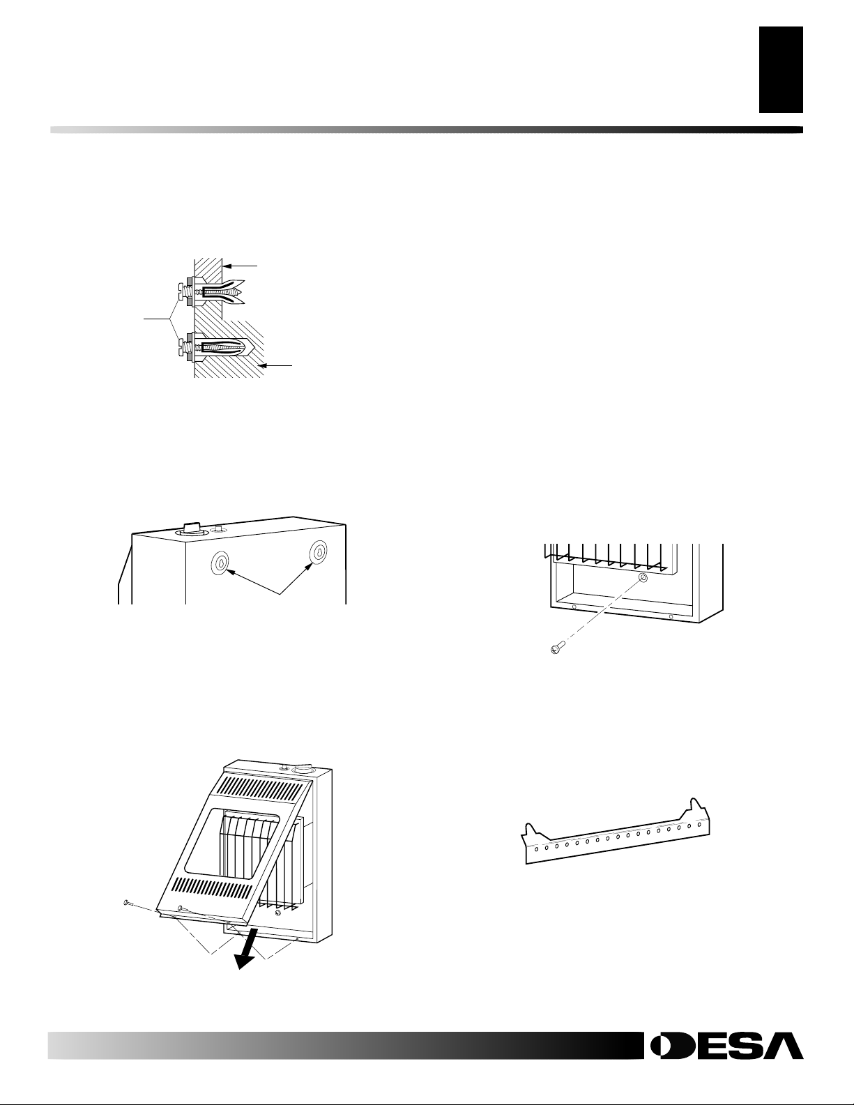
INSTALLATION
Suite
Installation des radiateurs à 1,8 et 2,9 kW (6 000 et 10 000 BTU/h) au mur (suite)
INSTALLATION
Installation des radiateurs à 5,9 kW (20 000 BTU/h) au mur
9
9
5. Serrez les deux vis jusqu’à ce qu’il reste un espace de 1,6 mm (1/16")
( l’épaisseur d’une pièce de 1 cent) entre le mur et les têtes des vis
(voir figure 9).
Mur mince
ou épais
(mur mince
Espace de
1,2 mm (1/16")
Figure 9 - Serrage des chevilles
illustré)
Mur
plein
Installation de la vis de montage inférieure
1. Repérez le trou de montage du bas. Il se trouve sur le panneau arrière
2. Marquez l’emplacement de la vis sur le mur.
3. Retirez le radiateur du mur.
4. Si vous mettez la vis de montage inférieure dans un mur creux ou
5. Remettez le radiateur contre le mur.
6. Faites passer la vis de la cheville inférieure par le panneau arrière et
Placement du radiateur sur les vis de montage
1. Repérez les deux encoches en trou de serrure sur le panneau arrière
du radiateur (voir figure 10).
2. Engagez les têtes des vis dans la partie la plus grande des encoches.
Faites glisser le radiateur vers le bas pour mettre les vis dans la petite
partie des encoches.
Encoche en trou
de serrure
Figure 10 - Emplacement des encoches en trou de serrure à
l’arrière du radiateur
Retrait du panneau avant du radiateur
1. Retirez deux vis près des coins inférieurs du panneau avant.
2. Soulevez la grille de protection verticalement jusqu’à ce qu’elle butte.
La grille de protection glissera de 6 mm [1/4"] environ.
3. Tirez la partie inférieure du panneau avant vers l’avant, puis vers le bas.
7. Serrez la vis jusqu’à ce que le radiateur soit bien fixé au mur. Prenez
Figure 12 - Installation de la vis de montage inférieure
INSTALLATION DES RADIATEURS À 5,9 KW
(20 000 BTU/H) AU MUR
Support de montage
Repérez le support de montage dans le carton du radiateur. Retirez le
support de montage du carton du radiateur.
du radiateur, près du bas (voir figure 12).
plein, installez la cheville pour mur. Suivez les étapes 1 à 5 de la
section Méthode de fixation avec une cheville pour mur, à la page 10.
Si vous mettez la vis de montage inférieure dans un poteau de cloison, percez un trou à l’emplacement indiqué avec un foret de 9/64".
insérez-la dans la cheville inférieure ou le trou que vous venez de
percer (voir figure 12).
soin de ne pas trop serrer.
Remarque :
ment. Il sera remis en place une fois les connexions au gaz et la recherche de fuites effectuées (voir les pages 11 et 12).
Ne remettez pas le panneau avant en place pour le mo-
Figure 11 - Retrait du panneau avant du radiateur
Pour plus de détails, visitez le site www.desatech.com
Pour plus de détails, visitez le site www.desatech.com
112157-01A
Figure 13 - Support de montage

10
INSTALLATION
Installation des radiateurs à 5,9 kW (20 000 BTU/h) au mur (suite)
INSTALLATION
Suite
Retrait du panneau avant du radiateur (modèles à 5,9
kW [20 000 BTU/h] uniquement)
1. Retirez les quatre vis peintes, deux de chaque côté du panneau avant.
2. Tirez la partie inférieure du panneau avant vers l’avant et sortez-le.
3. Retirez les emballages restants.
Figure 15 - Espaces à laisser libres autour du support de
montage
Fixation du support de montage au mur
Remarque :
partie du paquet de pièces. Le paquet de pièces est fourni avec le radiateur.
Méthode de fixation à un poteau de cloison
Pour fixer un support de montage à des poteaux de cloison
1. Percez des trous aux emplacements indiqués avec un foret de 9/64".
Figure 14 - Retrait du panneau avant du radiateur
Méthodes de fixation du support de montage au mur
N’utilisez que les deux trous extrêmes du support de montage pour fixer le
support au mur. Les centres de ces deux trous sont espacés de 35,5 cm (14").
Il y a deux façons de fixer le support de montage au mur :
1. Fixation à un poteau de cloison
2. Fixation à une cheville pour mur
Fixation à un poteau de cloison : Cette méthode offre la meilleure prise.
Faites passer les vis de montage par le support de montage et insérez-les
dans les poteaux de cloison.
Fixation à une cheville pour mur : Cette méthode vous permet de fixer un
support de montage à un mur creux (les parties de mur entre les poteaux) ou
à des murs pleins (en béton ou en maçonnerie).
Décidez laquelle de ces méthodes vous convient le mieux. Toutes les deux
offrent une prise fiable pour le support de montage.
Marquage de l’emplacement des vis
1. Avec du ruban adhésif, attachez le support de montage au mur là où le
radiateur sera placé. Vérifiez que le support de montage est de niveau.
AVERTISSEMENT : Respecter les écartements indiqués à la figure 15. Dans la mesure du possible, placer
l'appareil plus loin du sol et du mur attenant.
2. Marquez l’emplacement des vis sur le mur (voir la figure 15).
Note:
Ne marquez que les trous extrêmes du support de montage. Ne
faites passer des vis de montage que par ces trous.
3. Retirez le ruban adhésif et le support de montage du mur.
2. Placez le support de montage contre le mur. Alignez le dernier trou à
3. Faites passer les vis de montage par le support et insérez-les dans les
4. Serrez les vis jusqu’à ce que le support de montage soit bien fixé aux
Méthode de fixation avec une cheville pour mur
Pour fixer le support de montage aux murs creux (les parties de mur entre
les poteaux) ou aux murs pleins (en béton ou en maçonnerie)
1. Percez des trous aux emplacements indiqués avec un foret de 5/16".
2. Repliez la cheville comme l’indique la figure 16.
3. Insérez la cheville dans le trou (les ailettes en premier). Tapez sur la
4. Pour les murs minces (moins de 1,27 cm [1/2"], insérez une clavette
5. Placez le support de montage contre le mur. Alignez le dernier trou à
6. Faites passer les vis de montage par le support et insérez-les dans les
7. Serrez les vis jusqu’à ce que le support de montage soit bien fixé au mur.
20,3 cm
min.
(8")
N’utilisez que les trous
des extrémités pour les
Mur attenant
35,6 cm
(14")
vis de montage
Sol
47,7 cm
min.
(18 3/4")
Les chevilles pour mur, les vis de montage et les entretoises font
chaque extrémité du support sur les trous forés dans le mur.
poteaux de cloison.
poteaux de cloison.
Dans le cas de murs pleins (en béton ou en maçonnerie), percez un
trou d’au moins 2,5 cm (1") de profondeur.
cheville pour qu’elle soit à fleur de la surface du mur.
rouge dans la cheville. Poussez la clavette pour ouvrir les ailettes de
la cheville d’un coup sec.
IMPORTANT :
N’utilisez pas de marteau pour enfoncer la clavette!
Pour les murs épais (plus de 1,27 cm [1/2"] d’épaisseur) ou les murs
pleins, n’ouvrez pas les ailettes.
chaque extrémité du support sur les chevilles.
chevilles.
Figure 16 - Pliage de la cheville
Pour plus de détails, visitez le site www.desatech.com
Pour plus de détails, visitez le site www.desatech.com
Figure 17 - Ouverture des ailettes
de la cheville pour les murs minces
112157-01A

Montage du radiateur au sol avec le prêt-à-monter pour sol en option (5,9 kW [20 000 BTU/h] uniquement)
INSTALLATION
Suite
Installation des radiateurs à 5,9 kW (20 000 BTU/h) au mur (suite)
INSTALLATION
11
11
Placement du radiateur sur le support de montage
1. Repérez les deux fentes horizontales à l’arrière du radiateur.
2. Placez le radiateur sur le support de montage. Faites glisser les pattes
MONTAGE DU RADIATEUR AU SOL AVEC LE
PRÊT-À-MONTER POUR SOL EN OPTION (5,9 KW
[20 000 BTU/H] UNIQUEMENT)
en saillie du support de montage dans les fentes.
Montage des pieds sur le radiateur
Patte en saillie
Fentes
horizontales
Support de
montage (fixé
au mur)
1. Déposez l’habillage du radiateur sur son dos sur une table, en faisant
2. Alignez les trous du pied sur les trous de montage du fond de l’ha-
3. Fixez le pied au radiateur avec des vis à tôle.
4. Répétez cette procédure pour l’autre côté.
Montage des pieds au sol (si le code local l’exige)
Figure 18 - Montage du radiateur sur le support de montage
Installation des vis de montage inférieures
1. Repérez les deux trous de montage du bas. Ils se trouvent sur le panneau arrière du radiateur, près du bas (voir figure 19).
2. Marquez l’emplacement des vis sur le mur.
3. Retirez le radiateur du support de montage.
4. Si vous mettez les vis de montage inférieures dans un mur creux ou
plein, installez des chevilles pour mur. Suivez les étapes 1 à 4 de la
section Méthode de fixation avec une c heville pour mur, à la page 10.
Si vous installez les vis de montage inférieures dans un poteau de cloison, percez les trous aux emplacements indiqués avec un foret de 9/64".
5. Remettez le radiateur sur le support de montage.
6. Placez des entretoises entre les trous de montage inférieurs et les chevilles ou les trous forés.
7. Tenez l’entretoise en place d’une main. De l’autre, faites passer la vis
de montage par le trou de montage du bas et par l’entretoise. Placez
la pointe de la vis dans l’ouverture de la cheville ou du trou foré.
8. Serrez les deux vis jusqu’à ce que le radiateur soit bien fixé au mur.
Prenez soin de ne pas trop serrer.
Remarque :
Ne remettez pas le panneau avant en place pour le moment. Il sera remis en place une fois les connexions au gaz et la recherche de fuites effectuées (voir pages 11 et 12).
Radiateur
Mur
1. Retirez le panneau avant (voir Retrait du panneau avant du radia-
2. Placez le radiateur muni de ses pieds à l’emplacement de votre choix.
3. Si vous montez la base sur un parquet de bois, utilisez un foret de 1/8"
4. Remettez le radiateur muni de ses pieds sur les trous. Fixez la base au
dépasser le fond du radiateur du bord de la table.
billage (voir figure 20).
Si le radiateur doit être installé directement sur de la
moquette, de carrelage ou autre matériau combustible
(autre que du parquet de bois), le radiateur doit être déposé
sur un panneau de métal ou de bois qui recouvre la surface
qu’occupe le radiateur.
teur, à la page 10).
Marquez l’emplacement des trous à forer. Retirez le radiateur et sa base.
pour percez un trou de 2 cm (3/4") de profondeur (n’utilisez pas de
chevilles dans les parquets de bois).
Si vous montez la base sur un sol en béton, utilisez un foret à béton
de 1/4" pour percer un trou de 3,5 cm (13/8) de profondeur dans le sol.
Insérez les chevilles à fond dans les trous.
sol avec des vis à bois. Voir la figure 20.
Vis à
bois
Front View
Figure 19 - Installation des vis de montage inférieures
Pour plus de détails, visitez le site www.desatech.com
Pour plus de détails, visitez le site www.desatech.com
112157-01A
Side View
Vue de côtéVue de l’avant
Entretoise
Pied
Vis à tôle
Figure 20 - Installation des pieds (votre radiateur peut être
différent de celui de l’illustration)

12
INSTALLATION
Raccordement à l’alimentation en gaz
INSTALLATION
Suite
RACCORDEMENT À L’ALIMENTATION EN GAZ
L’installation doit comprendre une vanne d’arrêt de l’équipement, un
raccord et une prise NPT avec ouverture de 1/8". Placez la prise NPT à
portée pour y raccorder le manomètre de test. La prise NPT doit être en
amont du radiateur (voir figure 22).
IMPORTANT :
AVERTISSEMENT : Cet appareil nécessite un raccord
d'arrivée NPT (filetage de tuyau des USA) de 3/8" au régulateur de pression.
facile d’accès. La vanne d’arrêt de l’équipement sert à couper le gaz et à
rétablir son passage vers l’appareil.
Appliquez un peu de pâte d’étanchéité pour joints sur les filetages NPT
mâles. Ceci évitera d’avoir un excès de pâte pénétrant dans les tuyaux. Un
AVERTISSEMENT : Seul un technicien compétent doit
excès de pâte dans les tuyaux risquerait de boucher les vannes du radiateur.
raccorder le radiateur à l'alimentation en gaz. Respectez
tous les codes de votre localité.
AVERTISSEMENT : Pour le gaz naturel, ne jamais
raccorder le radiateur à des puits de gaz privés (qui n'appartiennent pas à une compagnie de gaz). Ce gaz est
communément appelé gaz de tête de puits.
Nous vous conseillons d’installer un piège à sédiments dans la conduite
d’arrivée comme l’indique la figure 22. Placez le piège à sédiments dans un
endroit facile d’accès pour le nettoyer. Installez les conduits entre l’arrivée
de l’alimentation en gaz et le radiateur. Placez le piège à sédiments là où les
matières attrapées ne risquent pas de geler. Un piège à sédiments recueille
IMPORTANT
de gaz avant de raccorder le radiateur à la canalisation. La pression de la
canalisation de gaz ne doit pas dépasser 26,6 cm (10,5") d’eau. Si la pression
de la canalisation de gaz est plus élevée, le régulateur du radiateur risque
d’être endommagé.
radiateur directement à la conduite de propane/LP. Ce radiateur
: Pour le gaz naturel, vérifiez la pression de la canalisation
l’humidité et les contaminants. De cette façon, ils ne vont pas dans les
contrôles du radiateur. Si le piège à sédiments n’est pas installé ou mal
installé, le radiateur risque de ne pas fonctionner correctement.
IMPORTANT :
lorsque vous le raccordez à la canalisation de gaz ou à un raccord. Prenez
ATTENTION : Pour le gaz propane/LP, ne raccordez jamais le
soin de ne pas serrer trop fort la connexion du tuyau au régulateur. Le boîtier
du régulateur risquerait d’être endommagé.
nécessite un régulateur externe (pas fourni). Installez le régulateur externe entre le radiateur et la conduite de propane/LP.
Pour le gaz propane/LP, l’installateur doit fournir un régulateur externe. Le
régulateur externe réduira la pression d’arrivée du gaz. Vous devez réduire
la pression d’arrivée du gaz pour qu’elle soit comprise entre 28 et 35,5 cm
(11" et 14") d’eau. Si vous ne réduisez pas la pression d’arrivée du gaz, vous
risquez d’endommager le régulateur du radiateur. Installez le régulateur
externe en dirigeant l’évent vers le bas comme l’indique la figure 21. Ceci
le protège de la pluie verglaçante et du verglas.
ATTENTION : N'utilisez que de la tuyauterie neuve, en
fer noir ou en acier. Un tuyau de cuivre étamé à l'intérieur
peut être utilisé à certains endroits. Vérifiez les codes de
votre localité. Utilisez une tuyauterie assez grosse pour
fournir un volume de gaz suffisant au radiateur. Si le tuyau
est trop petit, une baisse de volume excessive se produira.
Diamètre typique des tuyaux d’arrivée pour les modèles à 5,9 kW (20 000
BTU/h) - 3/8" ou plus.
Réservoir de
propane/PL
Régulateur externe
Évent dirigé
vers le bas
Gaz naturel
Du compteur de gaz
1,8/2,9 kW
(
[6/10 000 BTU/h]
Pression de 10 cm
[4"] à 26,7 cm [10,5"] d’eau
5,9 kW (20 000 BTU/h)
Pression de
12,7 cm [5"] à
26,7 cm [10,5"] d’eau)
Propane/LP
Du régulateur externe
(de 279 mm [11"] à 356 mm [14"]
de pression)
Figure 22 - Raccordement au gaz
* Une vanne d’arrêt de l’équipement dont la conception a été homologué
par CSA et dotée d’une prise NTP de 1/8" est une alternative acceptable à
la connexion de manomètre de test. Achetez la vanne d’arrêt de l’équipe-
Figure 21 - Régulateur externe avec évent dirigé vers le bas
(systèmes Propane/LP uniquement)
ment certifiée par la CSA en option chez votre revendeur. Consultez la
section Accessoires, à la page 29.
Installez une vanne d’arrêt de l’équipement dans un endroit
AVERTISSEMENT : Utiliser une pâte d'étanchéité pour
filets qui résiste au gaz liquéfié (PL).
Maintenez le régulateur de pression en place avec une clé
Mamelon de tube
NPT de 3/8"
Raccord à
joint rodé
Vanne d’arrêt
de l’équipement*
7,7 cm (3")
au minimum
Joint en T
Réduction
mâle-femelle
à NPT de 1/8"
Prise mère
NPT de 1/8"
Régulateur
de pression
Habillage du
radiateur
Joint en T
Mamelon
de tube
Couvercle
Connexion
de
manonètre
de test*
Piège à
sédiments
Pour plus de détails, visitez le site www.desatech.com
Pour plus de détails, visitez le site www.desatech.com
112157-01A

ON
POSITIO
OF
POSI
Vérification des connexions au gaz
INSTALLATION
13
13
INSTALLATION
Suite
Vérification de la pression des connexions de gaz du
radiateur
1. Ouvrez la vanne d’arrêt de l’équipement (voir figure 23).
VÉRIFICATION DES CONNEXIONS AU GAZ
2. Ouvrez la vanne de gaz principale, située sur ou près du compteur de
AVERTISSEMENT : Tester toutes les conduites de gaz et
les connexions pour détecter les fuites après l'installation
3. Assurez-vous que le bouton de réglage du radiateur est en position
ou la révision. Réparer toutes les fuites immédiatement.
4. Vérifiez tous les joints de la vanne d’arrêt de l’équipement à la vanne de
AVERTISSEMENT : Ne jamais utiliser de flamme nue pour
rechercher une fuite. Appliquer un liquide de détection de
fuite non corrosif sur tous les joints. La présence de bulles
indique une fuite. Réparer toutes les fuites immédiatement.
ATTENTION : Pour les installations au propane/PL,
5. Réparez toutes les fuites immédiatement.
6.
7. Éteignez le radiateur (consultez la section Pour couper le gaz de l’ap-
assurez-vous qu'un régulateur externe a été posé entre le
réservoir de propane/PL et le radiateur. Reportez-vous aux
consignes de la section
gaz
, à la page 12.
Raccordement à l'alimentation en
8. Remettez le panneau avant en place.
Test de la pression du système d’alimentation en gaz
Pressions de test excédant 3,5 kPa (3,5 PSIG)
1. Déconnectez l’appareil, avec son robinet de gaz principal (vanne de
contrôle) et la vanne d’arrêt de l’équipement, de la canalisation en
gaz. Les pressions dépassant 3,5 kPa (1/2 psig) endommageront le
régulateur du radiateur.
2. Fermez l’extrémité du conduit de gaz là où la vanne d’arrêt de l’équipement était raccordée.
3. Mettez sous pression le système de conduites d’alimentation en gaz
soit en ouvrant le robinet du réservoir de propane/PL, soit en ouvrant
la vanne de gaz principale située sur ou près du compteur de gaz
naturel, soit en utilisant de l’air comprimé.
4. Vérifiez tous les joints des conduites de gaz. Appliquez un liquide de
détection de fuite non corrosif sur tous les joints. La présence de bulles indique une fuite.
5. Réparez toutes les fuites immédiatement.
6. Raccordez à nouveau le radiateur et la vanne d’arrêt de l’équipement
à la conduite d’alimentation en gaz. Vérifiez s’il y a des fuites aux
raccords nouvellement connectés.
Pressions de test égales ou inférieures à 3,5 kPa (1/2 PSIG)
1. Fermez la vanne d’arrêt de l’équipement (voir figure 23).
2. Mettez sous pression le système de conduites d’alimentation en gaz
soit en ouvrant le robinet du réservoir de propane/PL, soit en ouvrant
la vanne de gaz principale située sur ou près du compteur de gaz
naturel, soit en utilisant de l’air comprimé.
3. Vérifiez tous les joints en aval du compteur de gaz s’il s’agit de gaz
naturel (voir figure 24) ou du réservoir de propane/LP s’il s’agit de
gaz propane/LP, à la vanne d’arrêt de l’équipement (voir figure 25).
Appliquez un liquide de détection de fuite non corrosif sur tous les
joints. La présence de bulles indique une fuite.
4. Réparez toutes les fuites immédiatement.
Figure 23 - Vanne d’arrêt de l’équipement
Figure 24 - Vérification des joints de gaz pour le gaz naturel
(modèle de 1,8 kW [6 000 BTU/h] illustré)
Figure 25 - Vérification des joints de gaz pour le gaz Propane/LP
(modèle de 1,8 kW [6 000 BTU/h] illustré)
gaz s’il s’agit de gaz naturel, ou ouvrez la vanne de réservoir de
propane/LP.
d’arrêt, « OFF ».
contrôle (voir figures 24 et 25). Appliquez un liquide de détection de fuite
non corrosif sur tous les joints. La présence de bulles indique une fuite.
Allumez le radiateur (consultez la section Utilisation du radiateur, aux
pages 14 et 15). Vérifiez que les autres joints internes ne fuient pas.
pareil, à la page 15).
Vanne d’arrêt de
l’équipement
Compteur
du gaz
Réservoir de
propane/PL
Ouverte
Fermée
Emplacement
de la vanne de
contrôle
Vanne d’arrêt
de
l’équipement
Emplacement
de la vanne de
contrôle
Vanne d’arrêt
de
l’équipement
112157-01A
Pour plus de détails, visitez le site www.desatech.com
Pour plus de détails, visitez le site www.desatech.com

UTILISATION DU RADIATEUR
14
Pour votre sécurité - À lire avant l’allumage
Instructions d’allumage
UTILISATION DU RADIATEUR
POUR VOTRE SÉCURITÉ - À LIRE
AVANT L’ALLUMAGE
AVERTISSEMENT : Si les instructions ne sont pas
suivies à la lettre, il y a un risque d'incendie ou d'explosion,
susceptible de causer des blessures et même la mort.
A. Cet appareil est muni d’une veilleuse qu’il faut allumer manuellement.
Quand vous allumez la veilleuse, suivez ces instructions à la lettre.
B. A VANT D’ALLUMER, vérifiez qu’il n’y aucune odeur de gaz tout
autour de l’appareil. Assurez-vous de vérifier près du sol parce
que le gaz est parfois plus lourd que l’air et va donc s’y déposer.
QUE FAIRE SI VOUS SENTEZ DU GAZ
• N’allumez aucun appareil.
• Ne touchez aucun interrupteur électrique et n’utilisez aucun
appareil téléphonique dans votre bâtiment.
• Allez chez un voisin et appelez immédiatement votre fournisseur de gaz. Suivez les instructions du fournisseur de gaz.
• Si vous ne pouvez pas joindre le f ournisseur, appelez le service
des incendies.
C. N’utilisez que votre main pour enfoncer ou tourner le bouton de
réglage du gaz. N’utilisez jamais d’outils. Si vous n’arrivez pas à
enfoncer ou à tourner le bouton à la main, n’essayez pas de le
réparer , mais appelez un technicien de service qualifié ou la compagnie de gaz. SI vous forcez le bouton ou que vous essa yez de le
réparer, il y a un risque d’incendie ou d’explosion.
D. N’utilisez pas cet appareil si une partie a été submergée. Appelez
immédiatement un technicien compétent pour inspecter l’appareil et remplacer toute pièce du système de contrôle et tout contrôle de gaz qui aurait été submergé.
INSTRUCTIONS
D’ ALLUMAGE
1. ARRÊTEZ ! Lisez les informations relatives à la sécurité ci-dessus.
2. Assurez-vous que la vanne d’arrêt de l’équipement est ouverte complètement.
3. Tournez le bouton de réglage dans le sens des aiguilles d'une montre
pour le mettre sur ARRÊT (voir figure 26 ou 27).
Clockwise
4. Attendez cinq (5) minutes pour évacuer le gaz. Puis essayez de détecter
une odeur de gaz, y compris au niveau du sol. Si vous sentez encore du
gaz, ARRÊTEZ ! Suiv ez les instructions la section « B » des inf ormations
relatives à la sécurité ci-dessus. Si vous ne sentez pas de gaz, passez à
l’étape suivante.
5. Poussez le bouton de réglage et faites-le tourner dans le sens inverse des
aiguilles d'une montre
tinuez à appuyer sur le bouton de réglage pendant cinq (5) secondes (voir
la figure 26 ou 27).
Remarque :
C’est peut-être la première fois que vous utilisez ce radiateur après l’avoir raccordé à l’alimentation en gaz. Dans ce cas, il faudra
peut-être appuyer sur le bouton de réglage pendant 30 secondes ou plus.
Ceci permettra de purger le système de l’air qui se trouve dans les tuyaux.
• Si le bouton de réglage ne ressort pas lorsque vous le relâchez, prenez
contact avec un technicien de service qualifié ou la compagnie de gaz
pour une réparation.
C-clockwise
pour le mettre sur VEILLEUSE. Con-
Pour plus de détails, visitez le site www.desatech.com
Pour plus de détails, visitez le site www.desatech.com
6. Pendant que le bouton de réglage est enfoncé, appuyez sur le bouton d’allumage et relâchez-le. Ceci allumera la veilleuse. La veilleuse est fixée à
l’avant du brûleur. Vous pouvez la voir en regardant par le panneau de
verre. Au besoin, continuez à appuyer sur le bouton d’allumage et à le
relâcher jusqu’à ce que la veilleuse s’allume.
Remarque :
Si la veilleuse ne reste pas allumée, reportez-vous à la sec-
tion Dépannage, aux pages 18 à 20. De plus, prenez contact avec un technicien de service qualifié ou la compagnie de gaz pour une réparation. En
attendant que les réparations soient faites, vous pouvez allumer la veilleuse
avec une allumette. Pour allumer la veilleuse avec une allumette, consultez la section Procédure d’allumage manuel, à la page 15.
7. Laissez le bouton de réglage enfoncé 30 secondes après avoir allumé la
veilleuse. Au bout de 30 secondes, relâchez le bouton de réglage.
• Si le bouton de réglage ne ressort pas lorsque vous le relâchez, prenez
contact avec un technicien de service qualifié ou la compagnie de gaz
pour une réparation.
Remarque :
Si la veilleuse s’éteint, répétez les étapes 3 à 7. Les modèles
de radiateurs à thermostat ont un système de verrouillage de sécurité.
Attendez une (1) minute avant de rallumer la veilleuse.
8. Modèles à contrôle manuel uniquement Tournez le bouton
de réglage dans le sens inverse des aiguilles d'une montre
C-clockwise
pour le mettre sur HA UT . Le brûleur principal de vrait s'allumer.
Réglez le bouton de réglage sur HAUT ou BAS. Pour tourner le
bouton de réglage de HAUT à B AS, appuyez sur le bouton et tournez-le dans le sens inverse des aiguilles d'une montre
Remarque :
Les positions HAUT et BAS sont des positions ver-
C-clockwise
.
rouillées. Si le bouton de réglage est sur une de ces positions, il
faut appuyer dessus pour pouvoir le tourner.
9. Modèles contrôlés par thermostat uniquement Tournez le
bouton de réglage dans le sens inverse des aiguilles d'une montr e
C-clockwise
au niveau de chauffage désiré. Le brûleur principal devrait s'allumer . Ajustez le bouton de contrôle à un niveau de chauffage entre 1 et 5.
ATTENTION : N'essayez pas de régler les niveaux de
chauffage avec la vanne d'arrêt de l'équipement.
Bouton
d’allumage
Bouton de réglage
Figure 26 - Bouton de réglage
sur ARRÊT (modèles
contrôlés manuellement)
Thermocouple
Figure 28 - Veilleuse
Bouton d’allumage
Bouton de réglage
T
O
L
I
P
F
F
O
Figure 27 - Bouton de réglage
sur ARRÊT (modèles contrôlés
par thermostat)
Électrode d’allumage
Brûleur de la veilleuse
112157-01A

UTILISATION DU RADIATEUR
G
Pour couper le gaz de l’appareil
Utilisation du contrôle par thermostat (modèles à thermostat uniquement)
Procédure d’allumage manuel
INSPECTION DU BRÛLEUR
Apparence de la flamme de la veilleuse
Apparence des flammes du brûleur
15
15
UTILISATION DU RADIATEUR
Suite
POUR COUPER LE GAZ
DE L’APPAREIL
Pour arrêter le radiateur
1. Appuyez sur le bouton de réglage et tournez-le dans le sens des
aiguilles d'une montre pour le mettre sur ARRÊT.
2. Coupez le courant à l’appareil s’il faut effectuer une révision ou
une réparation.
Pour n’éteindre que le brûleur (la veilleuse reste
allumée)
Tournez le bouton de réglage dans le sens des aiguilles d'une montre
pour le mettre sur VEILLEUSE.
Clockwise
UTILISATION DU CONTRÔLE
PAR THERMOSTAT (MODÈLES À
INSPECTION DU BRÛLEUR
Vérifiez souvent l’apparence de la flamme de la veilleuse et celle des
flammes du brûleur.
APPARENCE DE LA FLAMME DE LA VEILLEUSE
La figure 29 illustre l’apparence correcte de la flamme de la veilleuse. La
figure 30 illustre une apparence de flamme de veilleuse incorrecte. La
flamme de veilleuse incorrecte ne touche pas le thermocouple. De ce fait,
le thermocouple refroidira. Lorsqu’il refroidit, le radiateur s’éteint.
Si l’apparence de la flamme de la veilleuse n’est pas correcte, comme l’indique
la figure 30
• éteignez le radiateur (consultez la section Pour couper le gaz de l’ap-
• consultez la section Dépannage, aux pages 18 à 20
Remarque :
légèrement courbée, mais la flamme devrait être bleue, sans jaune ni orange.
Thermocouple
THERMOSTAT UNIQUEMENT)
Le contrôle thermostatique utilisé sur ces modèles est différent des
thermostats courants. Les thermostats courants se contentent d’éteindre et d’allumer le brûleur. Le thermostat utilisé sur le radiateur
détecte la température de la pièce. Le thermostat ajuste le débit de gaz
vers le brûleur. Cela augmente ou diminue la hauteur des flammes du
brûleur. Par moments, la température de la pièce peut dépasser celle
choisie sur le radiateur. Dans ce cas, le brûleur s’éteindra. Le brûleur
se rallume quand la température de la pièce retombe en dessous de la
température choisie. Le bouton de réglage peut être réglé sur n’importe quel niveau de chaleur entre « 1 » et « 5 ».
Remarque :
Le bulbe thermostatique mesure la température de l’air
près de l’habillage du radiateur. Elle ne correspond pas toujours à la
température de la pièce (en fonction de la construction de l’habitation,
du site de l’installation, de la taille de la pièce, des températures
extérieures, etc.). Vous pourrez déterminer votre niveau de confort
personnel en utilisant souvent le radiateur.
PROCÉDURE D’
ALLUMAGE MANUEL
1. Retirez le panneau avant (pour les radiateurs à 1,8 kW [6 000
BTU/h] et à 2,9 kW [10 000 BTU/h], consultez la figure 11, à la
page 9 ; pour le radiateur à 5,9 kW [20 000 BTU/h], consultez la
figure 14, à la page 10).
2. Suivez les étapes 1 à 5 de la section Instructions d’allumage, à la
page 14.
3. En appuyant sur le bouton de réglage, allumez une allumette.
Tenez l’allumette contre la veilleuse jusqu’à ce que la veilleuse
s’allume.
4. Laissez le bouton de réglage enfoncé 30 secondes après avoir al-
lumé la veilleuse. Au bout de 30 secondes, relâchez le bouton de
réglage. Suivez l’étape 8 de la section Instructions d’allumage, à
la page 14.
5. Remettez le panneau avant en place.
Figure 29 - Apparence correcte
de la flamme de la veilleuse
APPARENCE DES FLAMMES DU BRÛLEUR
La figure 31 illustre l’apparence correcte des flammes du brûleur. La figure 32 illustre
une mauvaise apparence des flammes du brûleur. La mauvaise apparence des
flammes du brûleur montre la formation de pointes jaunes sur les flammes. Elle
montre aussi des flammes plus hautes que la moitié de la hauteur du panneau de verre.
Si l’apparence des flammes du brûleur n’est pas correcte, comme l’indique la figure 32
• éteignez le radiateur (consultez la section Pour couper le gaz de l’ap-
• consultez la section Dépannage, aux pages 18 à 20
(les flammes des modèles GCN6 et GCP6 seront
plus courtes à cause de la moindre puissance)
Figure 31 - Apparence correcte
des flammes du brûleur
pareil, colonne 1)
La flamme de la veilleuse des appareils au gaz naturel sera
Flamme bleue
Brûleur de la
veilleuse
Thermocouple
Figure 30 - Mauvaise apparence
de la flamme de la veilleuse
Flamme jaune
Brûleur de
la veilleuse
AVERTISSEMENT : La formation de pointes jaunes
indique que le radiateur risque de produire de niveaux plus
élevés de monoxyde de carbone.
AVIS : Ne confondez pas les flammes oranges avec la
formation de pointes jaunes. Les flammes peuvent être
momentanément orange si des poussières ou d’autres
particules fines pénètrent dans le radiateur et sont brûlées.
pareil, colonne 1)
Formation de
pointes jaunes
Moitié de la hauteur
1/2
du panneau de verre
Figure 32 - Mauvaise apparence
des flammes du brûleur
112157-01A
Pour plus de détails, visitez le site www.desatech.com
Pour plus de détails, visitez le site www.desatech.com

NETTOYAGE ET ENTRETIEN
16
ODS/veilleuse et orifice du brûleur
Trous d’entrée d’air de la veilleuse et du brûleur
Habillage
NETTOYAGE ET ENTRETIEN
AVERTISSEMENT : Éteindre le radiateur et le laisser
refroidir avant de procéder au nettoyage.
ATTENTION : Les zones de contrôles, le brûleur, et les
voies d'aération du brûleur doivent toujours être propres.
Inspectez-les avant chaque usage. Faites inspecter le radiateur une fois l'an par un technicien de service qualifié.
Le radiateur aura besoin d'être nettoyé plus souvent s'il y
a trop de peluches provenant de la moquette ou de couvertures, ou de poils d'animaux familiers, etc.
AVERTISSEMENT : Si les ouvertures d'air primaire du brûleur deviennent sales, il risque d'y avoir
une production de suie et des dommages matériels.
Nettoyez aussi l’assemblage de la veilleuse. Si la flamme de la veilleuse a
une pointe jaune, c’est qu’il y a de la poussière ou de la saleté dans
l’assemblage de la veilleuse. Il y a un petit trou d’entrée d’air pour la
veilleuse à 5 cm (2") environ de l’endroit où la flamme de la veilleuse sort
de l’assemblage de la veilleuse (voir figure 33). L’appareil étant éteint,
soufflez doucement de l’air dans le trou d’entrée d’air. Vos pouvez utiliser
une paille pour souffler si vous n’avez pas d’air comprimé.
ODS/VEILLEUSE ET ORIFICE DU BRÛLEUR
• Utilisez un aspirateur, de l’air sous pression ou une petite brosse à soies
souples pour le nettoyage.
TROUS D’ENTRÉE D’AIR DE LA VEILLEUSE ET DU
BRÛLEUR
Les trous d’entrée d’air primaire laissent entrer le volume d’air nécessaire
pour le mélange au gaz. Cela produit une flamme de combustion propre. Ne
laisser pas la poussière, la saleté, les peluches et les poils d’animaux
familiers s’accumuler sur ces trous. Nettoyez ces trous d’entrée d’air avant
chaque saison de chauffage. Si des trous d’entrée d’air sont bouchés, de la
suie sera produite. Nous vous conseillons de nettoyer l’appareil tous les
trois mois pendant l’utilisation et de le faire inspecter une fois l’an par un
technicien de service qualifié.
Nous vous conseillons aussi de ne pas laisser la poussière et la saleté
s’accumuler sur le tube du brûleur ou sur l’assemblage de la veilleuse. Pour
nettoyer ces pièces, nous vous conseillons d’utiliser de l’air comprimé à 207
kPa (30 PSI) ou moins.Votre boutique informatique, votre quincaillerie ou
votre centre de bricolage vendent probablement des bonbonnes d’air
comprimé. Vous pouvez utiliser un aspirateur en position de soufflerie. Si
vous utilisez de l’air comprimé en bonbonne, suivez les instructions de la
bonbonne. Vous risqueriez d’endommager l’assemblage de la veilleuse si
vous ne suivez pas les instructions de la bonbonne.
1. Éteignez l’appareil, y compris la veilleuse. Laissez l’appareil refroi-
dir pendant trente minutes au minimum.
2. Inspectez le brûleur et la veilleuse pour voir s’il y a de la poussière ou
de la saleté.
3. Soufflez de l’air par les entrées ou les fentes, et les trous du brûleur.
4. N’insérez jamais d’objets dans le tube de la veilleuse.
Figure 33 - Trou d’entrée d’air de la veilleuse
HABILLAGE
Conduits d’air
• Utilisez un aspirateur ou de l’air comprimé pour le nettoyage.
Extérieur
• Utilisez un chiffon doux imbibé d’une solution d’eau savonneuse. Pas-
Assemblage
de la veilleuse
Entrée d’air de
la veilleuse
sez le chiffon sur l’habillage pour enlever la poussière.
Pour plus de détails, visitez le site www.desatech.com
Pour plus de détails, visitez le site www.desatech.com
112157-01A

DÉPANNAGE
DÉPANNAGE
17
17
Remarque :
mentaire, visitez le site Internet du service
technique de DESA à l’adresse
www.desatech.com.
Note :
placées en ordre d’opération.
Pour obtenir de l’aide supplé-
Toutes les rubriques de dépannage sont
SYMPTÔME
Il n’y a pas d’étincelle sur l’ODS/veilleuse quand
on appuie sur le bouton d’allumage
Il y a une étincelle sur l’ODS/veilleuse mais pas
d’allumage quand on appuie sur le bouton d’allumage
AVERTISSEMENT : Éteindre le radiateur et le laisser refroidir avant de
procéder à une révision ou à une répa-
ration. Seul un technicien compétent
peut entretenir et réparer le radiateur.
CAUSE POSSIBLE
1. L’électrode d’allumage est mal placée
2. L’électrode d’allumage est brisée
3. L’électrode d’allumage n’est pas raccordée
au câble de l’allumeur
4. Le câble de l’allumeur est pincé ou mouillé
5. Le câble de l’allumeur est coupé
6. L’allumeur piézo-électrique est défectueux
1. L’alimentation en gaz a été coupée ou la
vanne d’arrêt de l’équipement est fermée
2. Le bouton de réglage n’est pas sur « PILOT »
3. Le bouton de réglage n’était pas enfoncé
dans la position « PILOT »
4. Il y avait de l’air dans les conduites de gaz à
l’installation
5. Il n’y a plus de gaz (propane/LP uniquement)
6. L’assemblage ODS/veilleuse est bouché
7. Le régulateur de gaz est mal réglé
ATTENTION : N'utilisez ni fil, ni
aiguille, ni autre objet de ce genre
pour nettoyer l'assemblage ODS/
veilleuse. Vous risqueriez d'endommager l'assemblage ODS/veilleuse.
SOLUTION
1. Remplacez l’assemblage de la veilleuse
2. Remplacez l’assemblage de la veilleuse
3. Reconnectez le câble de l’allumeur
4. Dégagez le câble de l’allumeur s’il est pincé
par du métal ou un tuyau. Veillez à ce que le
câble de l’allumeur soit sec
5. Remplacez le câble de l’allumeur
6. Remplacez l’allumeur piézo-électrique
1. Restaurez l’alimentation en gaz ou ouvrez
la vanne d’arrêt de l’équipement
2. Tournez le bouton de réglage pour le mettre
sur « PILOT »
3. Appuyez sur le bouton de réglage quand il
est sur « PILOT »
4. Continuez à enfoncer le bouton de réglage. Répétez l’allumage jusqu’à ce que l’air soit purgé
5. Prenez contact avec votre compagnie de gaz
propane/PL
6. Nettoyez l’assemblage ODS/veilleuse (consultez la section Nettoyage et maintenance,
à la page 16) ou remplacez-le
7. Remplacez le régulateur de gaz
L’ODS/veilleuse s’allume mais la flamme s’éteint
quand on relâche le bouton de réglage
Pour plus de détails, visitez le site www.desatech.com
Pour plus de détails, visitez le site www.desatech.com
112157-01A
1. Le bouton de réglage n’est pas enfoncé à fond
2. Le bouton de réglage n’a pas été enfoncé
assez longtemps
3. Le système de verrouillage de sécurité a
été déclenché
4. La vanne d’arrêt de l’équipement n’est pas
ouverte à fond
5. Le thermocouple est déconnecté à la vanne
de contrôle
6. La flamme de la veilleuse ne touche pas le
thermocouple; de ce fait, le thermocouple refroidit, ce qui éteint la flamme de la veilleuse.
Ce problème peut être dû à une ou plusieurs
des causes suivantes :
A) Basse pression du gaz
B) Assemblage OSD/veilleuse sale ou par-
tiellement bouché
7. Le thermocouple est endommagé
8. La vanne de contrôle est endommagée
1. Enfoncez le bouton de réglage à fond
2. Une fois l’ODS/veilleuse allumée, laissez le bouton de réglage enfoncé pendant 30 secondes
3. Attendez une minute que le système de verrouillage de sécurité se réinitialise. Répétez
la procédure d’allumage
4. Ouvrez la vanne d’arrêt de l’équipement à
fond
5. Serrez à la main, puis donnez 1/4 de tour de
plus
6. A) Prenez contact avec votre fournisseur de
gaz naturel ou de propane/LP
B) Nettoyez l’assemblage ODS/veilleuse
(consultez la section Nettoyage et mainte-
nance, à la page 16) ou remplacez-le
7. Remplacez l’assemblage de la veilleuse
8. Remplacez la vanne de contrôle

DÉPANNAGE
18
DÉPANNAGE
Suite
SYMPTÔME
Le brûleur ne s’allume pas une fois l’ODS/
veilleuse allumé
Le brûleur tarde à s’allumer
Le brûleur a des retours de flamme pendant la
combustion
Les flammes du brûleur sont jaunes pendant la
combustion
CAUSE POSSIBLE
1. L’orifice du brûleur est bouché
2. La pression d’entrée du gaz est trop basse
1. La pression du collecteur est trop basse
2. L’orifice du brûleur est bouché
1. L’orifice du brûleur est bouché ou endommagé
2. Le brûleur est endommagé
3. Le régulateur de gaz est défectueux
1. Il n’y a pas assez d’air
2. Le régulateur de gaz est défectueux
3. Le brûleur est bouché ou sale
SOLUTION
1. Nettoyez l’orifice du brûleur (consultez la
section Nettoyage et maintenance, à la page
16) ou remplacez l’orifice du brûleur
2. Prenez contact avec votre fournisseur de gaz
naturel ou de propane/LP
1. Prenez contact avec votre fournisseur de gaz
naturel ou de propane/LP
2. Nettoyez l’orifice du brûleur (consultez la
section Nettoyage et maintenance, à la page
16) ou remplacez l’orifice du brûleur
1. Nettoyez l’orifice du brûleur (consultez la
section Nettoyage et maintenance, à la page
16) ou remplacez l’orifice du brûleur
2. Remplacez le brûleur
3. Remplacez le régulateur de gaz
1. Examinez le brûleur pour voir s’il y a de la
saleté ou des débris. Le cas échéant, nettoyez
le brûleur (consultez la section Nettoyage et
maintenance, à la page 16)
2. Remplacez le régulateur de gaz
3. Nettoyez le brûleur (consultez la section
Nettoyage et maintenance, à la page 16)
Il y a un peu de fumée ou d’odeur à la première
utilisation
Le radiateur produit un sifflement quand le brûleur est allumé
Le radiateur émet un cliquetis quand le brûleur
vient d’être allumé ou fermé
1. Il y a des résidus des processus de fabrication
1. Le bouton de réglage est mis sur « HI » quand
le brûleur est froid
2. Il y a de l’air dans la conduite de gaz
3. Les conduits d’air du radiateur sont bouchés
4. L ’orifice du brûleur est sale ou partiellement
bouché
1. Le métal se dilate au réchauffement ou se
contracte au refroidissement
1. Le problème disparaîtra après quelques heures de fonctionnement
1. Tournez le bouton de réglage pour le mettre
sur « LO » et laissez le radiateur chauffer
pendant une minute
2. Faites fonctionner le brûleur jusqu’à ce que
tout l’air soit purgé de la conduite. Faites
vérifier le gaz par la compagnie de gaz naturel ou de propane/LP locale
3. Respectez les espaces à laisser libres à l’installation (voir figure 4, à la page 7)
4. Nettoyez le brûleur (consultez la section Net-
toyage et maintenance, à la page 16) ou remplacez l’orifice du brûleur
1. Cela se produit avec la plupart des radiateurs.
Si le bruit vous semble excessif, consultez
un technicien compétent
Pour plus de détails, visitez le site www.desatech.com
Pour plus de détails, visitez le site www.desatech.com
112157-01A

DÉPANNAGE
Suite
DÉPANNAGE
AVERTISSEMENT : En cas d'odeur de gaz
• Fermez le gaz.
• N’allumez aucun appareil.
• Ne touchez aucun interrupteur électrique et n’utilisez pas d’appareil télépho-
nique dans votre bâtiment.
• Allez chez un voisin et appelez immédiatement votre fournisseur de gaz.
Suivez les instructions du fournisseur de gaz.
• Si vous ne pouvez pas joindre le fournisseur, appelez le service des incendies.
19
19
IMPORTANT :
avoir des odeurs. Les produits de nettoyage, les peintures, les décapants pour peinture, la fumée de
tabac, les colles et les adhésifs, les moquettes et les tissus neufs, etc., peuvent produire des vapeurs.
Ces vapeurs peuvent se mélanger à l’air de combustion et créer des odeurs.
Si vous faites fonctionner le radiateur où l’air contient des impuretés, il risque d’y
SYMPTÔME
Un dépôt de poudre blanche se forme dans la
chambre de combustion, sur les murs ou les
meubles à proximité
Le radiateur produit des odeurs inattendues
Le radiateur s’arrête brusquement (l’ODS fonctionne)
CAUSE POSSIBLE
1. Lorsque le poli pour meubles, la cire, les
nettoyants à tapis, etc. sont chauffés, un dépôt de poudre blanche risque de se produire
1. Le radiateur brûle des vapeurs de peinture,
de laque à cheveux, de colles, etc. (consultez la note
2. Il n’y a pas assez de gaz (propane/LP uniquement)
3. Fuite de gaz. Reportez-vous à l’avertis-
sement en haut de la page
1. Il n’y a pas assez d’air frais
2. La pression de la conduite de gaz est faible
3. L’assemblage ODS/veilleuse est partiellement bouché
IMPORTANT
ci-dessus)
SOLUTION
1. Éteignez le radiateur lorsque vous utilisez
du poli à meubles, de la cire, des nettoyants
à tapis ou d’autres produits de ce genre
1. Aérez la pièce. N’utilisez plus de produits
dégageant des odeurs lorsque le radiateur
fonctionne
2. Remplissez le réservoir (propane/LP uniquement)
3 Identifiez et réparez toutes les fuites (con-
sultez la section Vérification des connexions
au gaz, à la page 13)
1. Ouvrez les fenêtres et les portes pour ventiler
2. Prenez contact avec votre fournisseur de gaz
naturel ou de propane/LP
3. Nettoyez l’assemblage ODS/pilote (consultez la section Nettoyage et maintenance, à la
page 16)
Odeur de gaz même quand le bouton de réglage
est sur « OFF »
Odeur de gaz pendant la combustion
Il y a de l’humidité ou de la condensation sur les
fenêtres
Pour plus de détails, visitez le site www.desatech.com
Pour plus de détails, visitez le site www.desatech.com
112157-01A
1. Fuite de gaz. Reportez-vous à l’avertis-
sement en haut de la page
2. La vanne de contrôle est défectueuse
1. Il y a des corps étrangers entre la vanne de
contrôle et le brûleur
2. Fuite de gaz. Reportez-vous à l’avertis-
sement en haut de la page
1. Il n’y a pas assez l’air de combustion ou de
ventilation
1. Identifiez et réparez toutes les fuites (consultez la section Vérification des connexions
au gaz, à la page 13)
2. Remplacez la vanne de contrôle
1. Démontez le conduit de gaz et retirez les
corps étrangers
2. Identifiez et réparez toutes les fuites (consultez la section Vérification des connexions
au gaz, à la page 13)
1. Reportez-vous à la section sur les besoins
d’Air frais pour la combustion et la ventila-
tion (à la page 4)

20
VUE DÉTAILLÉE DU RADIATEUR
Modèles GCP6 et GCN6
VUE DÉTAILLÉE DU
RADIATEUR
MODÈLES À CONTRÔLE MANUEL
GCP6 ET GCN6
21
22
23
24
27
20
13
14
12
10
4
11
7
6
3
2
5
9
1
8
26
15
18
25
19
17
10
16
1
VEILLEUSE
Pour plus de détails, visitez le site www.desatech.com
Pour plus de détails, visitez le site www.desatech.com
112157-01A

LISTE DES PIÈCES
Cette liste contient les pièces de rechange utilisées dans votre radiateur. Quand vous commandez des pièces, reportez-vous aux instructions de la section Pièces de rechange, à la page 29 de ce manuel.
NUMÉRO DE PIÈCE
N° GCP6 GCN6 DESCRIPTION QTÉ
1 M11084-38 M11084-38 Vis, n° 10 x 3/8" 6
2 099467-07 099467-07 Panneau avant 1
3 099318-04 099318-04 Grille de protection 1
4 101108-01 101108-01 Pince de la grille de protection 2
5 102017-02 102017-02 Fixation inférieure du verre 1
6 098260-11 098260-11 Panneau de verre 1
7 099319-02 099319-02 Fixation supérieure du verre 1
8 M11084-27 M11084-27 Vis, n° 8 x 3/8" 4
9 099317-02 099317-02 Élément déflecteur 1
10 098271-09 098271-09 Câble de l'allumeur 1
11 098249-01 098249-01 Écrou, M5 2
12 110803-02 110803-01 Assemblage OSD/Veilleuse 1
12-1 110186-01 110186-01 Prêt-à-monter du thermocouple 1
13 104263-02 104263-01 Brûleur 1
14 099387-17 099387-17 Conduit de la veilleuse 1
15 104259-04 104259-03 Injecteur, 1 pièce 1
16 NJF-8C NJF-8C Écrou hexagonal 1
17 099415-18 099415-17 Régulateur de pression 1
18 099462-01 099462-01 Conduit du brûleur 1
19 099391-02 099391-02 Conduit du régulateur 1
20 099413-01 099413-02 Vanne de contrôle 1
21 ** ** Assemblage de l'habillage
22 097159-04 097159-04 Allumeur piézo 1
23 099393-02 099393-02 Bouton de réglage 1
24 098508-01 098508-01 Écrou de fixation de la vanne 1
25 098303-02 098303-02 Vis, n° 6 x 5/16" 2
26 099818-01 099818-01 Rondelle éventail interne 1
LISTE DES PIÈCES
Modèles GCP6 et GCN6
21
21
112157-01A
PIÈCES DISPONIBLES — PAS ILLUSTRÉES
100642-02 100642-02 Assemblage, Matériel 1
** Cette pièce n'est pas remplaçable à la maison.
Pour plus de détails, visitez le site www.desatech.com
Pour plus de détails, visitez le site www.desatech.com

22
VUE DÉTAILLÉE DU RADIATEUR
Modèles GCP10T et GCN10T
VUE DÉTAILLÉE DU
RADIATEUR
MODÈLES CONTRÔLÉS PAR THERMOSTAT
GCP10T ET GCN10T
10
4
7
6
3
5
9
21
20
14
13
12
11
1
8
14
15
19
22
10
16
23
18
17
2
1
VEILLEUSE
Pour plus de détails, visitez le site www.desatech.com
Pour plus de détails, visitez le site www.desatech.com
112157-01A

LISTE DES PIÈCES
Cette liste contient les pièces de rechange utilisées dans votre radiateur.
Quand vous commandez des pièces, reportez-vous aux instructions de
la section Pièces de rechange, à la page 29 de ce mode d’emploi.
NUMÉRO DE PIÈCE
N° GCP10T GCN10T DESCRIPTION QTÉ
1 M11084-38 M11084-38 Vis, n° 10 x 3/8" 6
2 099467-07 099467-07 Assemblage du panneau avant 1
3 099318-04 099318-04 Grille de protection 1
4 101108-01 101108-01 Pince de la grille de protection 2
5 102017-02 102017-02 Fixation inférieure du verre 1
6 098260-11 098260-11 Panneau de verre 1
7 099319-02 099319-02 Fixation supérieure du verre 1
8 M11084-27 M11084-27 Vis, n° 8 x 3/8" 4
9 099317-02 099317-02 Élément déflecteur 1
10 098271-09 098271-09 Câble de l'allumeur 1
11 098249-01 098249-01 Écrou, M5 2
12 110803-02 110803-01 Assemblage OSD/Veilleuse 1
12-1 110186-01 110186-01 Prêt-à-monter du thermocouple 1
13 104263-01 104263-01 Brûleur 1
14 099387-11 099387-11 Conduit de la veilleuse 1
15 104259-06 104259-05 Injecteur, 1 pièce 1
16 NJF 8C NJF 8C Écrou hexagonal 1
17 099415-18 099415-17 Régulateur de pression 1
18 104261-01 104261-01 Conduit du brûleur 1
19 104264-01 104264-01 Conduit du régulateur 1
20 098522-18 098522-11 Robinet de gaz du thermostat 1
21 ** ** Assemblage de l'habillage 1
22 097159-04 097159-04 Allumeur piézo 1
23 098303-02 098303-02 Vis, n° 6 x 5/16" 2
PIÈCES DISPONIBLES — PAS ILLUSTRÉES
100642-02 100642-02 Assemblage, Matériel 1
Modèles GCP10T et GCN10T
LISTE DES PIÈCES
23
23
112157-01A
** Cette pièce n'est pas remplaçable à la maison.
Pour plus de détails, visitez le site www.desatech.com
Pour plus de détails, visitez le site www.desatech.com

VUE DÉTAILLÉE DU RADIATEUR
24
Modèles GCN20T et GCP20T
VUE DÉTAILLÉE DU
RADIATEUR
MODÈLES CONTRÔLÉS PAR
THERMOSTAT
GCN20T ET GCP210T
7
20
4
12
13
11
10
9
8
14
18
15
1
10
17
19
16
6
3
5
2
Pour plus de détails, visitez le site www.desatech.com
Pour plus de détails, visitez le site www.desatech.com
112157-01A

LISTE DES PIÈCES
Cette liste contient les pièces de rechange utilisées dans votre radiateur. Quand vous commandez des pièces, reportez-vous aux instructions de la section Pièces de rechange, à la page 29 de ce manuel.
NUMÉRO DE PIÈCE
N° GCN20T GCP20T DESCRIPTION QTÉ
1 097159-04 097159-04 Allumeur piézo 1
2 107673-01 107673-01 Panneau avant 1
3 103476-01 103476-01 Grille de protection 1
4 098522-10 098522-11 Robinet de gaz du thermostat 1
5 104189-01 104189-01 Fixation inférieure du verre 1
6 098260-09 098260-09 Brûleur 1
7 ** ** Habillage 1
8 107894-10 107894-10 Assemblage du déflecteur 1
9 098271-09 098271-09 Câble de l'allumeur 1
10 098249-01 098249-01 Écrou, M5 2
11 110803-01 110803-02 Assemblage OSD/Veilleuse 1
110186-01 110186-01 Prêt-à-monter du thermocouple 1
12 103446-01 103446-01 Brûleur 1
13 099387-03 099387-03 Conduit de veilleuse de 3/16" 1
14 103845-06 103845-05 Injecteur 1
15 099066-02 099066-02 Support de montage 1
16 099415-17 099415-18 Régulateur de gaz 1
17 NJF 8C NJF 8C Écrou hexagonal 1
18 103255-02 103255-02 Conduit de sortie de 3/8" 1
19 103256-02 103256-02 Conduit d'arrivée de 3/8" 1
20 109303-04 109303-04 Déflecteur 1
PIÈCES DISPONIBLES — PAS ILLUSTRÉES
Modèles GCN20T et GCP20T
LISTE DES PIÈCES
25
25
112157-01A
100642-03 100642-03 Assemblage de matériel 1
** Cette pièce n'est pas remplaçable à la maison.
Pour plus de détails, visitez le site www.desatech.com
Pour plus de détails, visitez le site www.desatech.com

SPÉCIFICATIONS
26
DÉPÔTS DE PIÈCES
SPÉCIFICATIONS
GCP6 GCP10T GCP20T
kW (BTU/h) (variable) min./max. 1,3/1,8 (4 400/6 000) 1,5/2,9 (5 000/10 000) 2,9/5,9 (10 000/20 000)
Type de gaz Propane/LP uniquement Propane/LP uniquement Propane/LP uniquement
Ignition Piézo. Piézo. Piézo.
Réglage du régulateur de pression 203 mm d’eau (8") 203 mm d’eau (8") 203 mm d’eau (8")
Pression du gaz d’entrée
Maximum 356 mm d’eau (14") 356 mm d’eau (14") 356 mm d’eau (14")
Minimum 279 mm (11") 279 mm (11") 279 mm (11")
Dimensions (H x L x P)
Radiateur 52 x 34,3 x 12,7 cm 54,6 x 34,3 x 17,8 cm 61,6 x 46,4 x 17,8 cm
Boîte 62 x 41,8 x 18,4 cm 62 x 41,8 x 18,4 cm 66,7 x 52,4 x 25,1 cm
Poids
Radiateur 6,1 kg (13,5 livres) 6,4 kg (14 livres) 9 kg (20 livres)
Expédition 8,7 kg (19 livres) 8,7 kg (19 livres) 11,4 kg (25 livres)
1
(20
/2 x 13 1/2 x 5 pouces) (21 1/2 x 13 1/2 x 7 pouces) (24 1/4 x 18 1/4 x 7 pouces)
(24 3/8 x 16 7/
16
x 7 1/4 pouces) (24 3/8 x 16 7/
16
x 7 1/4 pouces) (26 1/4 x 20 5/
8
x 9 7/8 pouces)
GCN6 GCN10T GCN20T
kW (BTU/h) (variable) min./max. 1,3/1,8 (4 400/6 000) 1,5/2,9 (5 000/10 000) 2,9/5,9 (10 000/20 000)
Type de gaz Naturel uniquement Naturel uniquement Naturel uniquement
Allumage Piézo. Piézo. Piézo.
Réglage du régulateur de pression 76 mm d’eau (3") 76 mm d’eau (3") 76 mm d’eau (3")
Pression du gaz d’entrée (colonne d’eau)
Maximum 267 mm d’eau (10,5") 267 mm d’eau (10,5") 267 mm d’eau (10,5")
Minimum 102 mm d’eau (4") 102 mm d’eau (4") 127 mm d’eau (5")
Dimensions (H x L x P)
Radiateur 52 x 34,3 x 12,7 cm 52 x 34,3 x 17,8 cm 61,6 x 46,4 x 17,8 cm
(20 1/2 x 13 1/2 x 5 pouces) (20 1/2 x 13 1/2 x 7 pouces) (24 1/4 x 18 1/4 x 7 pouces)
Boîte 62 x 41,8 x 18,4 cm 62 x 41,8 x 18,4 cm 66,7 x 52,4 x 25,1 cm
(24 3/8 x 16 7/
16
x 7 1/4 pouces) (24 3/8 x 16 7/
16
x 7 1/4 pouces) (26 1/4 x 20 5/
8
x 9 7/8 pouces)
Poids, kg (livres)
Radiateur 6,1 kg (13,5 livres) 6,4 kg (14 livres) 9 kg (20 livres)
Expédition 8,7 kg (19 livres) 8,7 kg (19 livres) 11,4 kg (25 livres)
CENTRE DE SERVICE/DÉPÔT DE PIÈCES
Si vous avez des questions sur le service ou les pièces, adressez-les à :
DESA Canada
À l´attention de Brian Hall
2220 Argentia Rd. Unit 4
Mississaugua Ontario L5N2K7
Téléphone : 905-826-8010
Courriel : bjthedj@on.aibn.com
Pour plus de détails, visitez le site www.desatech.com
Pour plus de détails, visitez le site www.desatech.com
112157-01A

27
27
112157-01A
Pour plus de détails, visitez le site www.desatech.com
Pour plus de détails, visitez le site www.desatech.com

28
RUBAN
2701 Industrial Drive
P.O. Box 90004
Bowling Green, KY 42102-9004
USA
Affran-
chissement
Requis
Pour plus de détails, visitez le site www.desatech.com
Pour plus de détails, visitez le site www.desatech.com
RUBAN
112157-01A

PIÈCES DE RECHANGE
CONSEILS DE SERVICE
SERVICE TECHNIQUE
PUBLICATIONS POUR LE
SERVICE
ACCESSOIRES
29
29
PIÈCES DE RECHANGE
Note :
N’utilisez que des pièces de rechanges d’origine. Ceci protégera la
garantie des pièces remplacées sous garantie.
PIÈCES SOUS GARANTIE
Prenez contact avec les revendeurs autorisés de ce produit (voir Dépôt de
pièces, à la page 26). S’ils ne peuvent pas vous approvisionner en pièces de
rechange d’origine, appelez le service technique de DESA 1-866-672-6040
pour plus de renseignements.
Lorsque vous appelez DESA, ayez sous la main :
• votre nom
• votre adresse
• le modèle et le numéro de série de votre radiateur
• comment le radiateur est tombé en panne
• le type de gaz que vous utilisez (propane/PL ou naturel)
• la date de l’achat
En général, nous vous demanderons de retourner la pièce à l’usine.
PIÈCES QUI NE SONT PAS SOUS GARANTIE
Prenez contact avec les revendeurs autorisés de ce produit. S’ils ne peuvent
pas vous fournir les pièces de rechange d’origine, prenez contact avec le Dépôt
de pièces (voir page 26) le plus proche ou appeler DESA au 1-866-672-6040
pour obtenir des références.
Lorsque vous appelez DESA, ayez sous la main :
• le numéro du modèle de votre radiateur
• le numéro de la pièce de rechange
PUBLICATIONS POUR LE
SERVICE
Vous pouvez acheter un manuel d’entretien à l’adresse indiquée au dos de
ce manuel. Envoyez un chèque de 5,00 US$ à DESA.
ACCESSOIRES
Procurez-vous ces accessoires de radiateur auprès de votre revendeur. S’il ne
peut pas vous fournir ces accessoires, prenez contact avec le Dépôt de pièces
le plus proche (voir page 26) ou appelez DESA au 1-866-672-6040 pour
obtenir des références. Vous pouvez aussi nous écrire à l’adresse inscrite à
l’arrière de ce manuel.
VANNE D’ARRÊT DE L’ÉQUIPEMENT - GA5010
Pour tous les modèles. Vanne d’arrêt de l’équipement avec prise NTP de 1/8".
CONSEILS DE SERVICE
PRÊT-À-MONTER DE VENTILATEUR - GAC3250T
(110 V UNIQUEMENT)
Si la pression du gaz est trop basse
• la veilleuse ne reste pas allumée
• le brûleur tarde à s’allumer
• le radiateur ne produit pas la chaleur spécifiée
• pour les appareil à propane/LP, la réserve de gaz propane/LP est peutêtre faible
Vous pensez peut-être que la pression de gaz est trop basse. Dans ce cas,
prenez contact avec votre fournisseur de gaz.
Modèles à 5,9 kW (20 000 BTU/h) uniquement. Meilleure distribution
de la chaleur. Radiateur plus efficace. Toutes les instructions d’installation et d’utilisation sont incluses.
Le souffleur, contrôlé par thermostat, s’allume et s’éteint selon les besoins.
SERVICE TECHNIQUE
Vous avez peut-être d’autres questions concernant l’installation, le fonctionnement ou le dépannage. Si tel est le cas, communiquez avec le service
technique de DESA au 1-866-672-6040. Lorsque vous appelez, veuillez
avoir les numéros de modèle et de série de votre radiateur sous la main.
Vous pouvez aussi visiter le site Web du service technique de DESA à
l’adresse : www.desatech.com.
Pour plus de détails, visitez le site www.desatech.com
Pour plus de détails, visitez le site www.desatech.com
112157-01A
PRÊT-À-MONTER DE BASE - GAC4550
Modèles à 5,9 kW (20 000 BTU/h) uniquement. Pour placer le radiateur sur
le sol, éloigné d’un mur. Toutes les instructions d’installation et d’utilisation
sont incluses.

30
INFORMATION SUR LA GARANTIE
CONSERVEZ CETTE GARANTIE
Modèle
N° de série
Date de l’achat
Donnez toujours le numéro du modèle et le numéro de série lorsque vous communiquez avec le fabricant.
Nous nous réservons le droit de modifier ces spécifications à tout moment sans préavis. La seule garantie valable est notre garantie écrite de série. Nous
n’offrons aucune autre garantie, expresse ou implicite.
GARANTIE LIMITÉE
RADIATEURS À GAZ RÉSIDENTIELS SANS CONDUIT D’ÉVACUATION
DESA garantit ce produit contre les défauts de matériau et de composant pour une période de deux (2) ans à compter de la date de l’achat initial, à
condition que le produit ait été installé correctement et utilisé et entretenu conformément à toutes les instructions pertinentes. Pour faire une
réclamation sous cette garantie, vous devez soumettre le contrat de vente ou le chèque encaissé.
Cette garantie n’est valable que pour le premier acheteur au détail. Cette garantie couvre seulement le coût des pièces requises pour restaurer ce
radiateur à son état de fonctionnement normal. Les pièces remplacées sous la garantie DOIVENT être obtenues par l’entremise de revendeurs de ce
produit autorisés ou de DESA qui fournira des pièces d’origine. L’utilisation d’autres pièces que celles d’origine annule cette garantie. Ce radiateur
DOIT être installé par un installateur compétent conformément à tous les codes de votre localité ainsi qu’aux instructions fournies avec l’appareil.
Cette garantie ne couvre pas les pièces qui ne sont pas dans leur état d’origine à cause de l’usure normale, ni les pièces qui se brisent ou sont
endommagées à la suite d’une mauvaise utilisation, d’accidents, de manque d’entretien, ou de défauts causés par une installation défectueuse. Les
frais de transport, de diagnostic, de main d’œuvre et tout autre frais de ce genre encourus pour réparer un radiateur défectueux sont de la responsabilité
du propriétaire.
DANS TOUTE L’ÉTENDUE PERMISE PAR LA LOI DE L’AUTORITÉ QUI RÉGIT LA VENTE DE CE PRODUIT, CETTE GARANTIE
EXPRESSE REMPLACE TOUTE AUTRE GARANTIE EXPRESSE ET LIMITE LA DURÉE DE CETTE GARANTIE ET DE TOUTE AUTRE
GARANTIE TACITE, INCLUANT LES GARANTIES DE QUALITÉ MARCHANDE ET DE CONFORMITÉ À UN USAGE PARTICULIER À
DEUX (2) ANNÉES À COMPTER DE LA DATE DE L’ACHAT INITIAL; LA RESPONSABILITÉ DE DESA SE LIMITE AU PRIX D’ACHAT
DU PRODUIT ET DESA NE POURRA ÊTRE TENUE RESPONSABLE DE TOUT AUTRE DOMMAGE INDIRECT, INCIDENT OU
IMMATÉRIEL.
Dans les états et les provinces qui ne permettent pas de limiter la durée de validité d’une garantie implicite, ni l’exclusion de dommages incidents
ou immatériels, les limites et exclusions relatives aux garanties implicites ou aux dommages ne s’appliquent pas.
Cette garantie vous donne des droits spécifiques selon la loi et vous pourriez aussi avoir d’autres droits selon l’état ou la province que vous habitez.
Pour tout renseignement concernant cette garantie, écrivez à :
DESA Industries of Canada, Inc.
2220, Argentia Road, Unité 4
Mississauga, Ontario
L5N 2K7
905-826-8010
Télécopie : 905-826-8236
www.desatech.com
courriel : desacan@sympatico.ca
112157 01
NOT A UPC
Pour plus de détails, visitez le site www.desatech.com
Pour plus de détails, visitez le site www.desatech.com
112157-01
Rev. A
10/03
112157-01A
 Loading...