

PROPANE/LP CONSTRUCTION FORCED AIR HEATER
OWNER’S MANUAL
55,000 BTU MODELS TB100, TB104, TB106, TB110
85,000 BTU MODELS TB102, TB111, TB114
125,000 BTU TB101, TB105, TB107, TB112
170,000 BTU TB103, TB108, TB113
IMPORTANT: Read and understand this manual before
assembling, starting or servicing heater. Improper use
of heater can cause serious injury. Keep this manual for
future reference.
GENERAL HAZARD WARNING: Failure to comply
with the precautions and instructions provided with this
heater, can result in death, serious bodily injury and
electrical shock.
Only persons who can understand and follow the in-
structions should use or service this heater.
If you need assistance or heater information such as an in-
structions manual, labels, etc. Contact the manufacturer.
Save this manual for future reference.
For more information, visit www.desatech.com
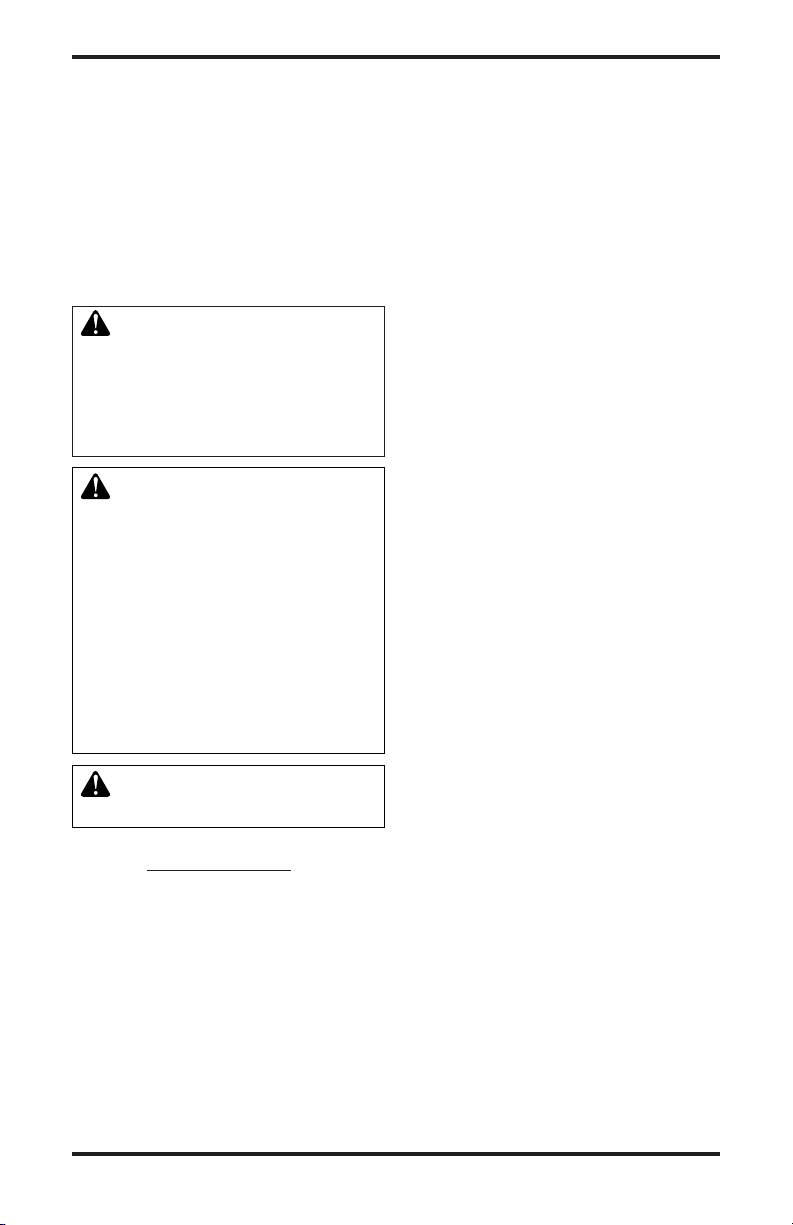
TABLE OF CONTENTS
Safety Information ............................................... 2
Product Identication ........................................... 3
Unpacking............................................................ 4
Assembly ............................................................. 4
Theory of Operation............................................. 4
Propane Supply ................................................... 5
Ventilation ............................................................ 5
Installation ........................................................... 5
Operation ............................................................. 6
Storage ................................................................ 7
SAFETy INFORMATION
WARNING: This product
chemicals known to the State
of California to cause cancer or
birth defects or other reproductive harm.
WARNING: Fire, burn, inhala-
solid combustibles, such as building materials, paper or cardboard,
a safe distance away from the
heater as recommended by the
instructions. Never use the heater
in spaces which do or may contain
volatile or airborne combustibles
or products such as gasoline, solvents, paint thinner, dust particles
or unknown chemicals.
WARNING: Not for home or
recreational vehicle use.
The heater is designed and approved for
use as a construction heater under ANSI
Z83.7•CGA 2.14-2000 Construction Heater.
The purpose of construction heaters is to
provide temporary heating of buildings under
construction, alteration or repair. Properly
used, the heater provides safe economical
heating. Products of combustion are vented
into the area being heated.
We cannot foresee every use which may be
made of our heaters. Check with your local
about heater use.
Other standards govern the use of fuel gases and
heat producing products for specic uses. Your
local authorities can advise you about these.
www.desatech.com
Maintenance ........................................................ 7
Service Procedures ............................................. 8
Specications ...................................................... 9
Wiring Diagrams ................................................ 10
Replacement Parts .............................................11
Technical Service................................................11
Service Publications ...........................................11
Accessories ........................................................11
Illustrated Parts Breakdown and Parts List........ 12
Warranty and Repair Service ............................ 18
Some people are
more affected by carbon monoxide than others. Early signs of carbon monoxide poisoning
resemble the flu, with headaches, dizziness
and/or nausea. If you have these signs, the
heater may not be working properly. Get fresh
air at once! Have heater serviced.
Propane/LP gas is odorless.
An odor-making agent is added to propane/LP
gas. The odor helps you detect a propane/LP
gas leak. However, the odor added to propane/LP gas can fade. Propane/LP gas may
be present even though no odor exists.
Make certain you read and understand all
warnings. Keep this manual for reference. It
is your guide to safe and proper operation of
this heater.
1. Install and use heater with care. Follow
all local ordinances and codes. In the
absence of local ordinances and codes,
refer to the Standard for Storage and
Handling of Liqueed Petroleum Gas,
ANSI/NFPA 58 and the Natural Gas and
Propane Installation Code CSA B149.1.
This instructs on the safe storage and
handling of propane gases.
2. Use only the electrical voltage and fre-
quency specied on model plate. The
electrical connections and grounding of
the heater shall follow the National Electric
Code, ANSI/NFPA 70 or the Canadian
Electric Code, Part 1.
3. Electrical grounding instructions - This
appliance is equipped with a three-prong
(grounding) plug for your protection against
shock hazard and should be plugged directly into a properly grounded three-prong
receptacle or extension cord.
4. This product has been approved for use in
the Commonwealth of Massachusetts.
5. For indoor use only. Provide adequate
ventilation.
6. Keep heater away from strong drafts,
wind, water spray, rain or dripping water.
119143-01A2
SAFETy INFORMATION
Continued
7. Use only in well-vented areas. Before using
heater, provide at least a three-squarefoot opening of fresh, outside air for each
100,000 Btu/Hr (105,500 k/j) of rating.
8. Do not use heater outdoors or in occupied
dwellings.
9. Do not use heater in living or sleeping
quarters.
10. Keep appliance area clear and free from
combustible materials, gasoline, paint
thinner and other flammable vapors and
liquids. Dust is combustible. Do not use
heater in areas with high dust content.
11. If this heater is equipped with a thermostat. Heater may start at anytime.
12. Check heater for damage before each
use. Do not use a damaged heater.
13. Use only propane/LP gas set up for vapor
withdrawal.
14.
Keep propane tank(s) below 100° F (38° C).
15. Do not use heater in a basement or below
ground level. Propane/LP gas is heavier
than air. If a leak occurs, propane/LP gas
will sink to the lowest possible level.
16. Use only the hose and factory regulator
provided with the heater.
17. Check hose before each use of heater. If
highly worn or cut, replace with hose speci-
ed by manufacturer before using heater.
18. Do not alter heater. Keep heater in its
original state.
19. Do not use heater if altered.
20. Keep heater at least 6 feet (1.8 m) from
propane/LP tank(s). Do not point heater at
propane/LP tank(s) within 20 feet (6.1 m).
21. Minimum heater clearances from combustibles: Outlet: 8 Ft. (2.4 m), Sides: 2
Ft. (0.6 m), Top: 6 Ft. (1.8 m), Rear: 2 Ft.
(0.6 m).
22. Locate heater on stable and level surface
if heater is hot or running.
23. Keep children and animals away from
heater.
24. Turn off propane/LP supply and unplug
heater when not in use.
25. Never block air inlet (rear) or hot air outlet
(front) of heater.
26. Never move, handle or service a hot,
operating or plugged in heater.
27. Never attach duct work to front or rear of
heater.
28. Use only original replacement parts. This
heater must use design-specic parts.
Do not substitute or use generic parts.
Improper replacement parts could cause
serious or fatal injuries.
29. Do not use this product without leg and
foot assembly.
PRODUCT
IDENTIFICATION
Burn Rate
Adjustment
Automatic
Gas Control
Valve Button
Air Inlet
(Rear)
Figure 1 - 55/85/125,000 Btu/Hr Models
Burn Rate
Adjustment
Knob
Air Inlet
(Rear)
Knob
Cord Cleat
Thermostat
Knob
Figure 2 - 170,000 Btu/Hr Models
Handle
Adjustable Foot
Handle
Cord Cleat
Hot Air
Outlet
(Front)
Hot Air Outlet
(Front)
Adjustable
Foot
119143-01A 3
www.desatech.com
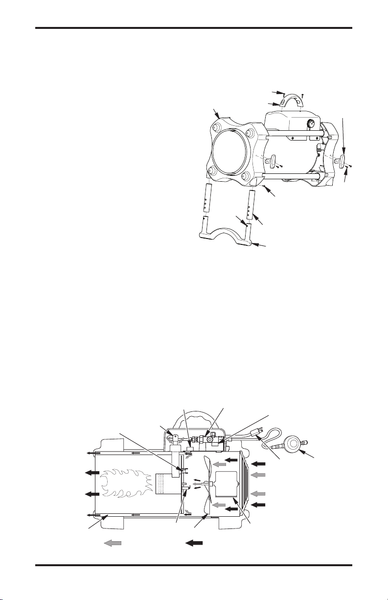
Air For
Combustion
Air For
Heating
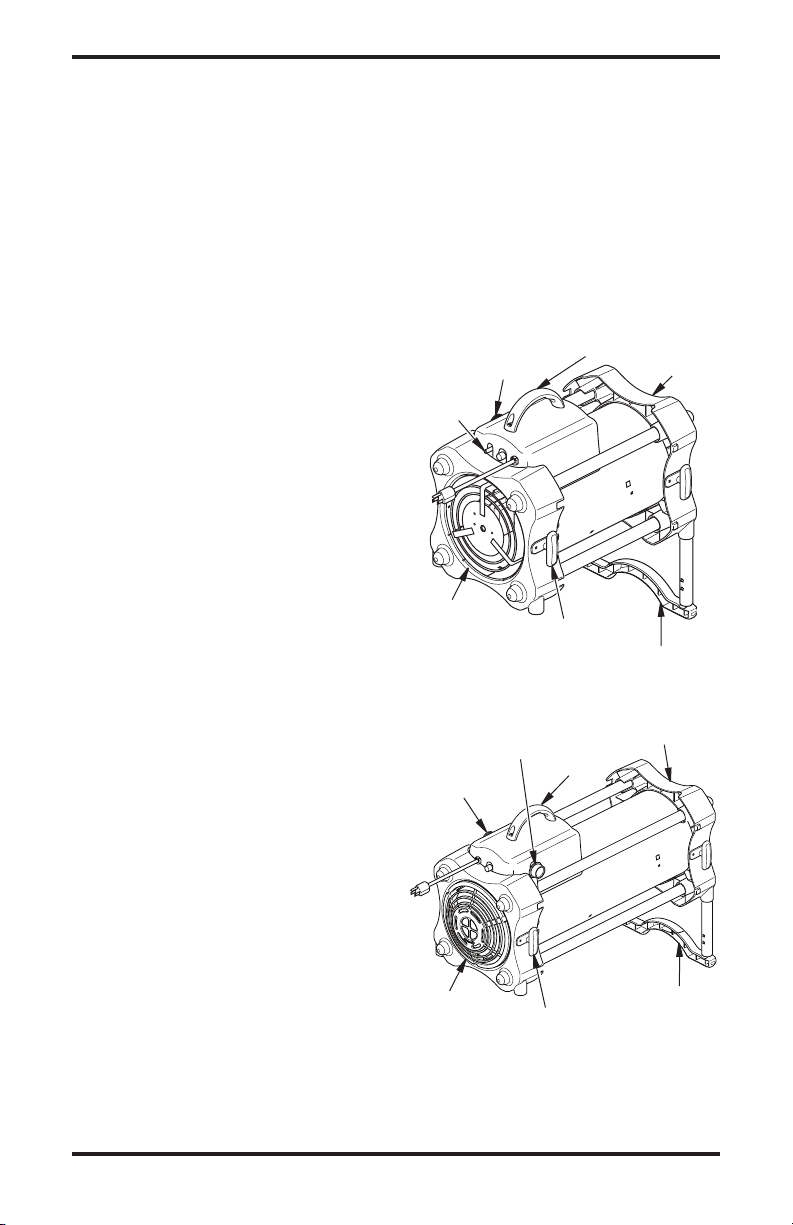
UNPACkINg
1. Remove all packing items applied to
heater for shipment. Keep plastic cover
cap (attached to heater inlet connector and
hose/regulator assembly) for storage.
2. Remove all items from carton.
3. Check all items for shipping damage. If
heater is damaged, promptly inform dealer
where you bought heater.
Small post screws on plastic foot will snap
into holes in leg extensions.
Cord Cleats
Install cord cleats on side of end caps as shown
in Figure 3 with screws provided (short).
Long screws
Outlet
End Cap
Handle
Cord
Cleat
ASSEMBLy
IMPORTANT: Do not use this product without
leg and foot assembly.
Handle
Attach handle to control box with 2 screws
(long) as shown in Figure 3.
1. Insert leg extensions into outlet end cap
until small hole lines up with larger hole,
visible from inside of outlet end cap (see
Figure 3). Fasten leg extensions with
provided screws (short).
2. Insert plastic foot ends into each leg extension and set heater to desired angle.
Leg Extension
Small
Post
Figure 3 - Handle and Foot Assembly
Fastening
Screw (short)
Leg Extension
Plastic Foot
Short
Screw
THEORy OF OPERATION
The Fuel System: The hose/regulator assembly attaches to the propane gas supply. For
55/85/125 models, the propane gas moves through the automatic control valve, burn rate
adjustment valve and out the injector. For 170 models, the propane gas moves through the
solenoid valve, burn rate adjustment valve and out the injector.
The Air System: The motor turns the fan. The fan pushes air into and around the combustion
chamber. This air is heated and provides a stream of clean, hot air.
The Ignition System: For 55/85/125 models the high voltage ignitor sends voltage to the spark
ignitor. For 170 models direct spark ignitor sends voltage to the spark ignitor. The spark ignitor
ignites the fuel and air mixture.
The Safety Control System: This system causes the heater to shut down if the flame goes
out. The motor will continue to run, but no heat is produced.
High Voltage Ignitor (55/85/125
Models) or DSI (170 Models)
Thermal
Limit Switch
Injector
Automatic Control Valve
(55/85/125 models only)
Solenoid Valve
(170 models only)
Clean
Heated
Air Out
(Front)
Combustion
Chamber
Spark Ignitor
Figure 4 - Cross Section Operational View
www.desatech.com
Fan
Motor
Power
Cord
Cool
Air In
(Back)
Hose/
Regulator
Assembly
119143-01A4
PROPANE SUPPLy
Propane/LP gas and propane/LP tank(s) are
to be furnished by the user.
Use this heater only with a propane/LP vapor
withdrawal supply system. See Chapter 5
of the Standard for Storage and Handling
of Liqueed Petroleum Gas, ANSI/NFPA 58
and the Natural Gas and Propane Installation
Code CSA B149.1. Your local library or re
department will have these booklets.
The amount of propane/LP gas ready for use
from propane/LP tanks varies. Two factors
decide this amount:
1. The amount of propane gas in tank(s)
2. The temperature of tank(s)
The chart below shows the number of 100 lb
(45 kg) tanks needed to run this heater.
Number of tanks
Temperature Models
above 20° F (-7° C) 1 1 2
20° F (-7° C) to -0 (-18° C)
Less gas is vaporized at lower temperatures.
You may need a larger tank in colder weather.
Your local propane/LP gas dealer will help you
select the proper supply system.
1 2 3
VENTILATION
WARNING: Follow the mini-
mum fresh, outside air ventila-
fresh, outside air ventilation is
poisoning can occur. Provide
proper fresh, outside air ventilation before running heater.
Provide a fresh air opening of at least
three square feet for each 100,000 Btu/Hr
(105,500 k/j) rating. Provide extra fresh air
if more heaters are being used.
INSTALLATION
WARNING: Review and understand the warnings in the
Safety Information section, page
2. They are needed to safely operate this heater. Follow all local
codes when using this heater.
WARNING: Test all gas piping
and connections for leaks after
installing or servicing. Never use
and water to all joints. Bubbles
forming show a leak. Correct all
leaks at once.
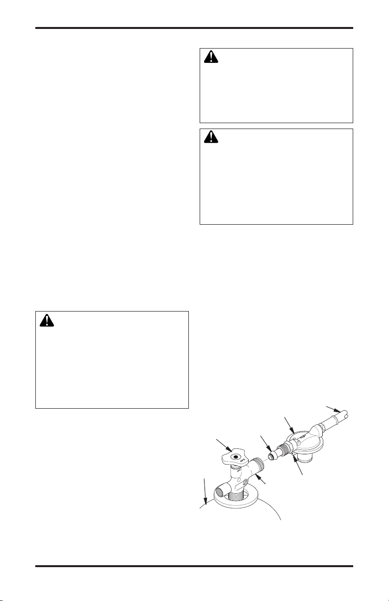
1. Provide propane/LP supply system (see
Propane/LP Supply).
2. Connect POL tting on hose/regulator
assembly to propane/LP tank(s). Turn
POL tting counterclockwise into threads
on tank. Tighten rmly using a wrench.
IMPORTANT: Tighten regulator with vent
pointing down. Pointing vent down protects regulator from weather damage.
3. Connect hose to inlet connector of heater.
Tighten rmly using a wrench.
IMPORTANT: Extra hose or piping may be
used if needed. Install extra hose or piping
between propane/LP tank and regulator.
You must ensure a minimum of 25 psig
at the inlet of the regulator. You must use
the regulator supplied with the heater.
Hose
Regulator
Supply
Valve
Propane
Tank
POL Fitting
Fuel Gas
Connector
Heater
Connector
Vent (pointing
down)
To
Inlet
Figure 5 - Regulator With Vent Pointing
119143-01A 5
www.desatech.com
Down
INSTALLATION
Continued
4. Op en propane /LP suppl y va lve on
propane/LP tank(s) slowly. Note: If not
opened slowly, excess-flow check valve
on propane/LP tank will stop gas flow. If
this happens, you may hear a click inside
the regulator assembly. To reset the ex-
cess flow check valve, close propane/LP
supply valve and open again slowly.
5. Check all connections for leaks.
6. Close propane/LP supply valve.
Inlet Connector
Gas Valve
Button
Hose
Figure 6 - Hose and Inlet Connector
(Heater may vary from illustration)
OPERATION
WARNING: Review and understand the warnings in the
Safety Information section, page
2. They are needed to safely operate this heater. Follow all local
codes when using this heater.
TO START HEATER
1. Follow all installation, ventilation and
safety information.
2. Locate heater on stable and level surface.
Make sure strong drafts do not blow into
front or rear of heater.
3. Plug power cord of heater into a threeprong, grounded extension cord. Extension cord must be at least six feet long.
Extension cord must be UL listed.
www.desatech.com
Up to 50 feet (15 m) long, use 18 AWG
rated cord.
51 to 100 feet (15.5 to 30.5 m) long, use
16 AWG rated cord.
101 to 200 feet (30.78 to 61 m) long, use
14 AWG rated cord.
4. Plug extension cord into a 120 volt/60
hertz, three-hole, grounded outlet.
5. Op en propane /LP suppl y va lve on
propane/LP tank(s) slowly. Note: If not
opened slowly, excess-flow check valve
on propane/LP tank will stop gas flow. If
this happens, you may hear a click inside
the regulator assembly. To reset the ex-
cess flow check valve, close propane/LP
supply valve and open again slowly.
6. Adjust variable Btu control knob fully
clockwise to LO.
55, 85, 125 Models Only
7. Press and hold in gas valve button. Heater
should ignite within a few seconds.
Note: If heater fails to ignite, hose may have
air in it. If so, keep gas valve button pressed
and wait 20 seconds. Release gas valve
button and wait 20 seconds for unburned
fuel to exit heater. Repeat step 6.
8. After heater ignites, wait 30 seconds. This
activates the automatic control system.
Release the gas control valve button.
9. Adjust thermostat to desired setting. If
heater does not start, thermostat setting
may be too low. Turn thermostat knob to
higher position to start heater. Note: If
heater does not start, unplug heater. Wait
ten seconds for safety control to reset,
plug in heater, then try again.
All Models
10. When burner remains lit, set heater to the
desired heat level by turning the variable
Btu control knob counterclockwise. If
burner goes out, turn off gas. Turn variable Btu control knob fully clockwise to
the lowest position. Check fuel supply. If
adequate fuel is available, restart heater
beginning at step 1.
TO STOP HEATER
1. Tightly close propane/LP supply valve on
propane tank(s).
2. Wait a few seconds. Heater will burn gas
left in supply hoses.
3. Unplug heater.
119143-01A6
OPERATION
Continued
TO RESTART HEATER
If safety control stops gas flow to heater, motor
will continue to run.
1. Unplug heater.
2. Wait ten seconds. Plug heater in.
If heater does not restart
A. Check supply valves (on propane/LP
tank). Make sure they are open.
B. Check fuel level in propane/LP tank(s). If
fuel level is too low, contact local propane/
LP gas company.
If heater still does not restart, contact your
local service center.
STORAgE
CAUTION: Disconnect heater
from propane supply tank(s).
1. Store propane/LP tank(s) in safe manner.
See chapter 5 of Standard for Storage and
Handling of Liqueed Petroleum Gases,
ANSI/NFPA 58 and the Natural Gas and
Propane Installation Code CSA B149.1.
Follow all local codes.
2. Place plastic cover caps over brass ttings on inlet connector of heater and
hose/regulator assembly.
3. Store in dry, clean and safe place. Do
not store hose/regulator assembly inside
heater combustion chamber.
4. When taking heater out of storage, always
check inside of heater. Insects and small
animals may place foreign objects in
heater. Keep inside of heater free from
combustible and foreign objects.
MAINTENANCE
WARNING: Never service
heater while it is plugged in,
connected to propane supply,
operating or hot. Severe burns
and electrical shock can occur.
1. Keep heater clean. Clean heater annually
or as needed to remove dust and debris. If
heater is dirty or dusty, clean heater with
a damp cloth.
2. Inspect heater before each use. Check
connections for leaks. Apply mixture of
liquid soap and water to connections.
Bubbles forming show a leak. Correct all
leaks at once.
3. Inspect hose/regulator assembly before
each use. If hose is highly worn or cut,
replace.
4. Have heater inspected yearly by a quali-
ed service agency.
5. Keep inside of heater free from combustible and foreign objects.
119143-01A 7
www.desatech.com
SERVICE PROCEDURES
WARNING: Never service
heater while it is plugged in,
connected to propane supply,
operating or hot. Severe burns
and electrical shock can occur.
CLEANING FAN
Clean fan every 500 hours of operation or
as needed.
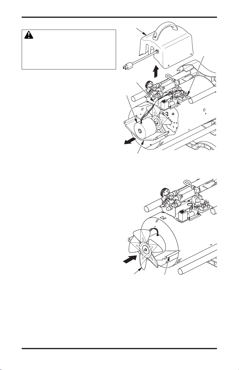
1. Remove screws on top cover using 5/16"
nut-driver or Phillips head screw driver.
2. Remove top cover.
3. Detach the 2 black motor wires from terminal block under top cover. Be sure to
detach only wires coming from motor.
4. Remove fan guard from rear of heater.
Fan guard will snap out of shell.
5. Reach into rear of heater shell. Carefully
pull motor wires through hole in bracket.
Note: Pull wires through hole one at a
time.
6. Remove screws holding motor mount to
shell. Use 5/16" nut driver or Phillips head
screw driver.
7. Carefully pull motor and fan out of shell.
IMPORTANT: Be careful not to damage
fan. Do not set motor and fan down with
the weight resting on fan. This could damage fan pitch.
8. Turn motor and fan around. Place motor
and fan into shell backwards. Note: Motor
will go into shell rst (see Figure 8).
9. Line up rear mounting holes in shell with
rst hole on each side of motor mount (see
Figure 8). Note: When holes are lined up,
fan should be outside of shell.
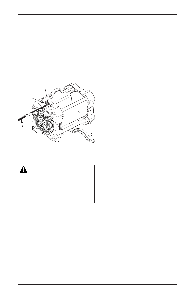
10. Holding mounting screws, carefully reach
through fan blades into rear of heater. Be
careful not to damage fan pitch. Insert
screw through motor mount and shell.
With free hand, attach screw nger tight.
Repeat process for other mounting hole.
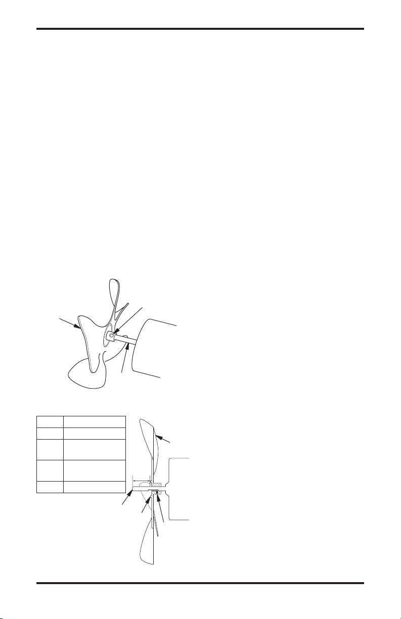
11. Use 1/8" hex wrench to loosen setscrew
which holds fan to motor shaft (see Figure 9, page 9).
12. Slip fan off motor shaft.
13. Clean fan using soft cloth moistened with
a cleaning solvent.
Top Cover
Terminal
Block
Hole in
Bracket
Motor
Motor Mounting
Bracket
Figure 7 - Removing Fan and Motor
Fan
Figure 8 - Fan and Motor Reversed for
Motor Mounting
Bracket
Cleaning
www.desatech.com
119143-01A8
A
SERVICE PROCEDURES
Continued
14. Dry fan thoroughly.
15. Replace fan on motor shaft. Place set-
screw on flat of shaft. See chart in Figure
10 for distance of fan hub from end of
motor shaft. Tighten setscrew rmly (40-
50 inch-pounds).
16. Remove screws securing motor mount to
shell.
17. Pull motor and fan from shell. Turn motor
and fan around. Carefully place back in
shell. Note: Fan will go into shell rst.
18. Line up mounting holes in shell with
holes on motor mount. Replace 4 screws
through shell and motor mount.
19. Route motor wires through hole in top of
shell (see Figure 7, page 8).
20. Reconnect motor wires to the same posts
on terminal block as removed in step 3,
page 8 (see Figure 7, page 8).
21. Replace top cover.
22. Replace fan guard.
Fan
Motor
Shaft
Figure 9 - Fan, Motor Shaft and Setscrew
Model Distance A
55 0.19" (4.8 mm)
85
125
170 0.25" (6.4 mm)
* Depending
on Motor Shaft
Identication
0.5" (12.7 mm)* or
0.9" (22.9 mm)*
0.5" (12.7 mm)* or
0.9" (22.9 mm)*
Motor
Shaft
Setscrew
Hub
Fan
Motor
Setscrew
SPECIFICATIONS
All Models
• Propane/LP Gas
• Gas Supply Pressure to Regulator:
Max - Bottle Pressure, Min - 25 psig
(172.4 kPa)
• Gas Supply Pressure Regulator Out:
20 psig (137.9 kPa)
• Electrical Input: 120V, 60 Hz, 1Ø, 3a
• Direct Spark Ignition
• Minimum Ambient Temp. Rating:
0° F (-17.8° C)
• 30 - 55,000 Btu/Hr (8.8 - 16.1 kW)
• Fuel Consumption:
1.4 - 2.6 pounds/hr (0.70 - 1.28 kg/hr)
• Primary Flame Control:
Thermocouple operated gas valve
• Heated Air Output: 300 CFM (8.49 m3/min)
• 50 - 85,000 Btu/Hr (14.6 - 25.0 kW)
• Fuel Consumption:
2.3 - 3.9 pounds/hr (1.04 - 1.77 kg/hr)
• Primary Flame Control:
Thermocouple operated gas valve
• Heated Air Output: 350 CFM (9.91 m3/min)
• 75 - 125,000 Btu/Hr (21.9 - 36.6 kW)
• Fuel Consumption:
3.5 - 5.8 pounds/hr (1.59 - 2.63 kg/hr)
• Primary Flame Control:
Thermocouple operated gas valve
• Heated Air Output: 350 CFM (9.91 m3/min)
• 125 - 170,000 Btu/Hr (36.6 - 49.8 kW)
• Fuel Consumption:
5.8 - 7.9 pounds/hr (2.63 - 3.6 kg/hr)
• Primary Flame Control:
DSI Flame Rectication
•
Heated Air Output: 450 CFM (12.74 m3/min)
Figure 10 - Fan Cross Section
119143-01A 9
www.desatech.com
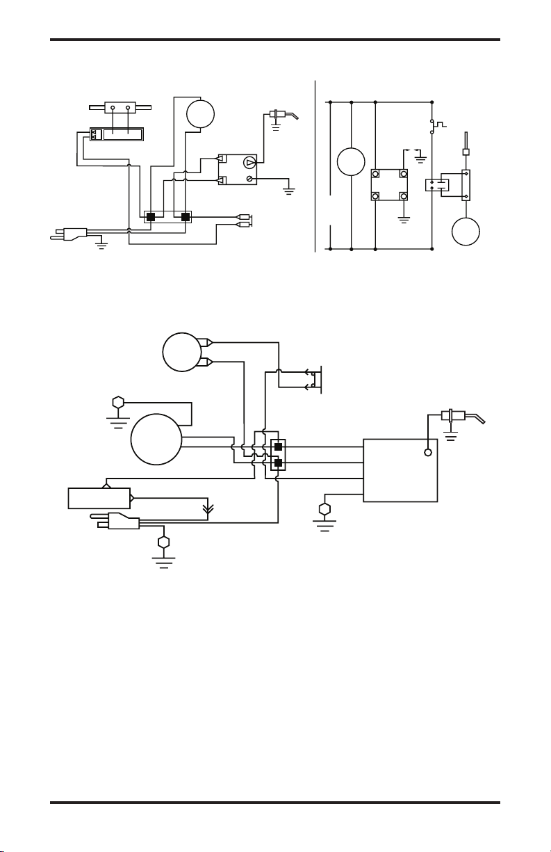
WIRINg DIAgRAMS
Electrode/Electrodo/
Électrode
Orange**/
Naranja**/
Orange**
CONNECTION DIAGRAM/
DIAGRAMA DE CONEXIONES/
SCHÉMA DE CONNEXION
Green/Verde/Vert
• If any original wiring as supplied with the heater must be replaced, it must be replaced with type
AWG 105° C wire or its equivalent except as indicated (*Type SF2-200. **UL Style 3257 250° C)
• Si es necesario reemplazar algún cable suministrado originalmente con el calentador, éste se debe
reemplazar con cable tipo AWG 105° C o su equivalente, excepto cuando se indica locontrario
(*Tipo SF2-200. **UL Style 3257 250° C)
• Si le câblage original fourni avec l'appareil de chauffage doit être remplacé, faites-le avec du câble de
type AWG 105° C ou son équivalent, sauf indication contraire (*Type SF2-200. **UL Style 3257 250° C)
High Limit Switch/
Interruptor de
límite alto/
Commutateur de
limite supérieure
Gas Valve/
Válvula de gas/Vanne de gaz
Green/
Verde/
Vert
Green/Verde/Vert
Motor/
Moteur
Flame Control/
Control de llama/
Contrôle de
la flamme
Line/Línea/Ligne
Neut/Neutral/Neutre
Valve/Válvula/Vanne
Ground/Tierra/Masse
White/Blanco/Blanc
White/
Blanco/
Blanc
White/Blanco/Blanc
Blue*/Azul*/Bleu*
Blue*/Azul*/Bleu*
Blue*/
Azul*/
Bleu*
Black/Negro/Noir
Black/Negro/Noir
Black/Negro/
Noir
Black/
Negro/
Noir
Black/Negro/Noir
Thermostat/
Termostato
Chassis Ground/
Conexión a tierra
del chasis/Masse
Chassis Ground/
Conexión a tierra
del chasis/Masse
Chassis Ground/
Conexión a tierra
del chasis/Masse
Line Cord/
Cable de alimentaión/
Cordon d'alimentation
Black** or Orange**/
Negro** o Naranja**/
Noir** ou orange**
L1
L2
White/Blanco/
Blanc
Blue*/Azul*/Bleu*
Blue*/Azul*/Bleu*
Blue/Azul/Bleu
White/Blanco/
Blanc
White/Blanco/Blanc
Black/
Negro/Noir
Black/Negro/Noir
Black/Negro/Noir
Black/Negro/Noir
Green/
Verde/
Vert
Orange/
Naranja
Orange/
Naranja
Orange/
Naranja
Orange/
Naranja
Thermocouple/Termopar
CONNECTION DIAGRAM/DIAGRAMA DE CONEXIONES/
DIAGRAMME DE CONNEXION
SCHEMATIC DIAGRAM/DIAGRAMA ESQUEMÁTICO/
DIAGRAMME DE CIRCUIT
Relay/Relé/Relais
Motor/
Moteur
Ignitor/
Encendedor/
Allumeur
High-Limit Switch/
Interruptor de
límite alto/
Commutateur de
limite supérieure
• If any original wiring as supplied with the heater must be replaced, it must be replaced with type AWG 105° C
wire or its equivalent except as indicated (*Type SF2-200. **UL Style 3257 250° C)
• Si es necesario reemplazar algún cable suministrado originalmente con el calentador, éste se debe reemplazar con
cable tipo AWG 105° C o su equivalente, excepto cuando se indica lo contrario (*Tipo SF2-200. **UL Style 3257 250° C)
* Si le câblage fourni avec l'appareil de chauffage doit être remplacé, faites-le avec du câble de type AWG 105° C
ou son équivalent, sauf indication contraire (*Type SF2-200. **UL Style 3257 250° C)
Line Cord/
Cable de línea/
Cordon électrique
Motor/
Moteur
High Limit Switch/
Interruptor de límite alto/
Interrupteur de
limite supérieure
White/Blanco/Blanc
Black/Negro/Noir
115V
60HZ
Gas
Valve
Relay/
Relé/
Relais
Thermocouple/
Termopar
Green/Verde/Vert
L1
L2
Ignitor/
Encendedor/
Allumeur
Válvula de gas/
Robinet de gaz
Electrode/Electrodo/
Électrode
Electrode/Electrodo/
Électrode
55,000, 85,000 and 125,000 Btu/Hr Models
170,000 Btu/Hr Models
www.desatech.com
119143-01A10
REPLACEMENT PARTS
WARNING: Use only original
replacement parts. This heater
Do not substitute or use generic
parts. Improper replacement
parts could cause serious or fatal injuries. This will also protect
your warranty coverage for parts
replaced under warranty.
PARTS UNDER WARRANTY
Contact authorized dealers of this product. If
they can’t supply original replacement part(s),
either contact your nearest Parts Central or
call DESA Heating Products’ Technical Service Department at 1-866-672-6040. When
calling DESA Heating Products, have ready:
• your name
• your address
• model and serial numbers of your heater
• how heater was malfunctioning
• purchase date
In most cases, we will ask you to return the
part to the factory.
PARTS NOT UNDER WARRANTY
Contact authorized dealers of this product. If
they can’t supply original replacement part(s),
either contact your nearest Parts Central or call
DESA Heating Products at 1-866-672-6040
for referral information. When calling DESA
Heating Products, have ready:
• model number of your heater
• the replacement part number
TECHNICAL SERVICE
You may have further questions about this heater.
If so, contact DESA Heating Products’ Technical
Service Department at 1-866-672-6040. When
calling, please have your model and serial numbers of your heater ready.
You can also visit DESA Heating Products’ Technical Service web site at www.desatech.com.
SERVICE PUBLICATIONS
You can purchase a service manual for $5.
Make check payable to DESA Heating Products. Send your request to DESA Heating
Products (address on back page). Be sure to
include the heater model number.
ACCESSORIES
Purchase accessories and parts from your
nearest dealer or service center. If they can
not supply an accessory or part, either contact
your nearest Parts Central (listed in the sepa-
rate Authorized Service Center booklet) or call
DESA Heating Products at 1-866-672-6040.
You can also write to the address listed on the
back page of this manual.
A POL adapter with excess flow check valve.
119143-01A 11
www.desatech.com
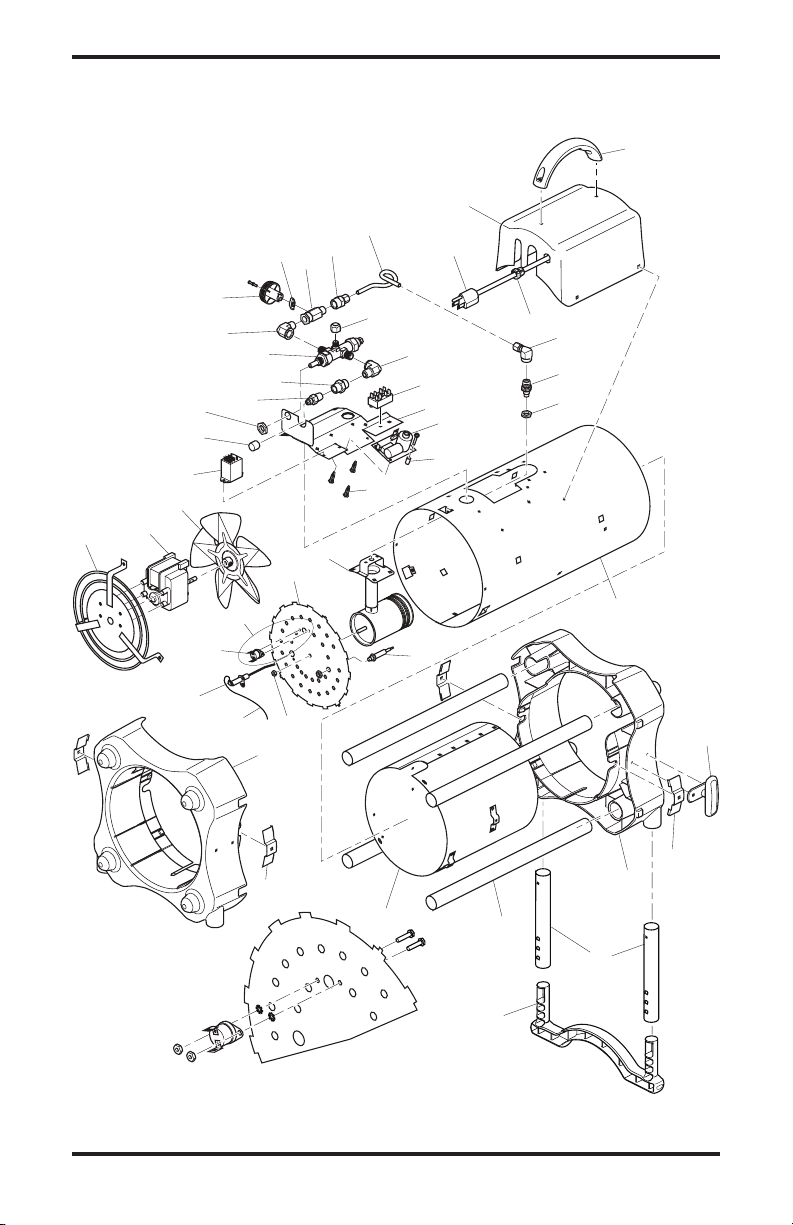
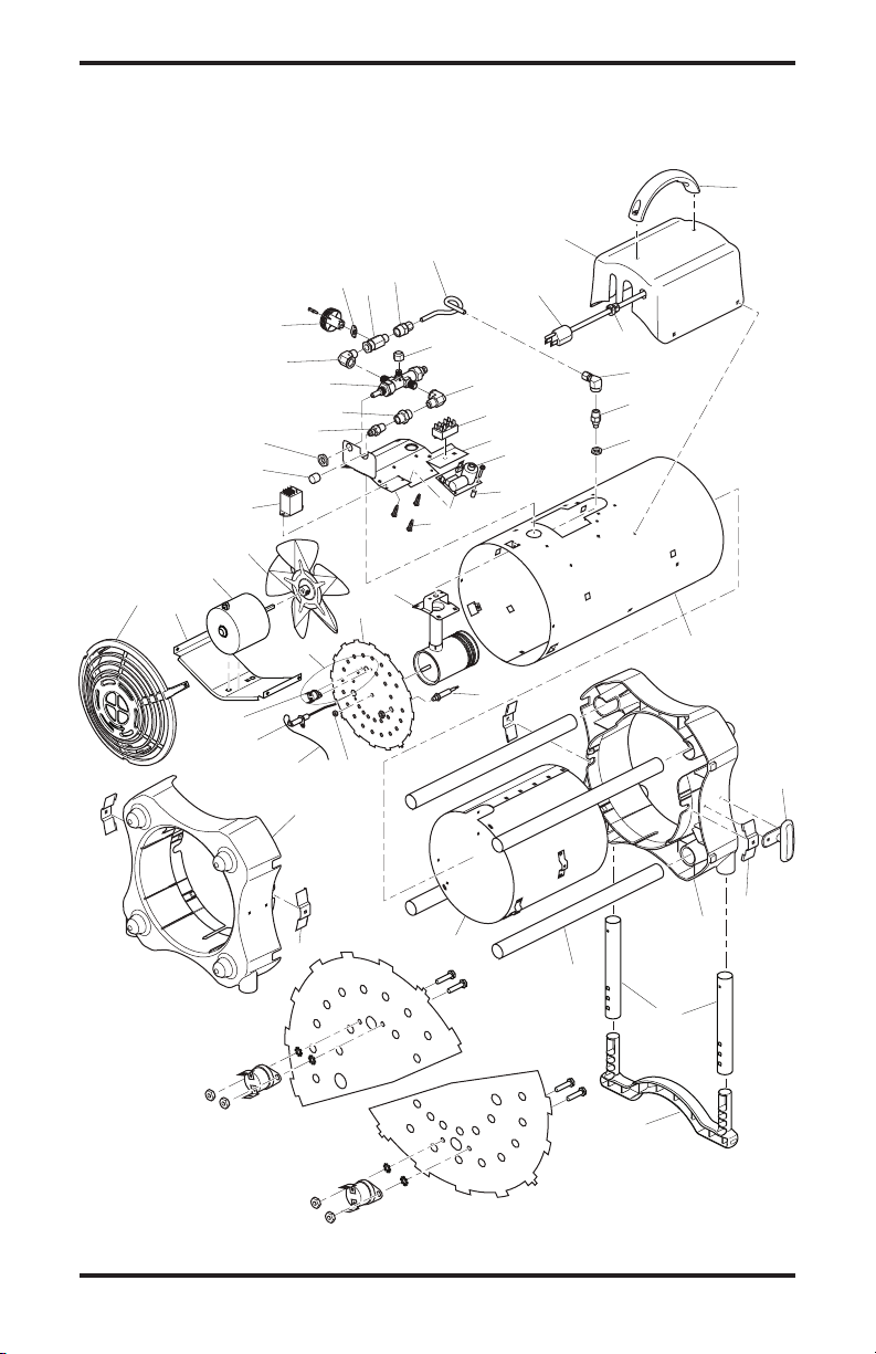
ILLUSTRATED PARTS BREAkDOWN
41
42
36
40
39
38
36
29
35
32
22
16
15
14
13
18
12
20
19
17
10
11
30
Detail A
Detail A
25
24
23
28
26
31
27
10
9
8
7
6
5
34
33
43
4
2
3
21
1
37
37
www.desatech.com
119143-01A12
PARTS LIST
This list contains replaceable parts used in your heater. When ordering parts, follow the
instructions listed under Replacement Parts on page 11 of this manual.
KEY
NO. PART NO. DESCRIPTION QTY.
1 118476-01 Handle • • • • 1
2 118472-01 Control Box • • • • 1
3 M11143-2 Strain Relief Bushing • • • • 1
4 098219-42 Power Supply Cord Assembly • • • • 1
5 100145-03 Fuel Tube • • • • 1
6 118796-01 Female Compression Fitting • • • • 1
7 114159-05 Ball Valve Assembly • • • • 1
8 113810-01 Ball Valve Knob Insert • • • • 1
9 118773-01 Ball Valve Knob • • • • 1
10 113870-01 Elbow Fitting • • • • 2
11 116981-01 Female Cap Fitting • • • • 1
12 097155-01 Control Valve • • • • 1
13 113869-01 Coupling Fitting • • • • 1
14 097809-04 Male Fitting • • • • 1
15 113794-01 Valve Nut • • • • 1
16 078978-03 Cap Sleeve • • • • 1
17 119401-01 Terminal Block • • • • 1
18 118506-01 Heat Shield • • • • 1
19 113867-01 Hi-Lo Mini Ignitor • • • • 1
20 114150-01 Steel Spacer • • • • 1
21 118802-01 Printed Circuit Board Support • • • • 3
22 113875-02 Relay Assembly • • • • 1
23 118780-01 Motor Grill Assembly • • • • 1
24 113880-02 Motor Assembly • • • • 1
25 113881-01 Fan • • • • 1
26 097805-04 Ignitor • • • • 1
27 097806-03 Ignitor Cable • • • • 1
28 101481-12 Thermal Limit Switch • • • • 1
29 098249-01 Nut • • • • 1
30 118497-02 Rear Plate • • • • 1
31 104146-05 Thermocouple • • • • 1
32 118514-01 Burner Assembly • • • • 1
33 118685-01 Injector • • • • 1
34 100146-01 Female Elbow • • • • 1
35 119496-01 Shell (Black) • • • • 1
36 118471-01 End Cap • • • • 2
37 119459-01 Hold Down Bracket • • • • 4
38 119497-01 Combustion Chamber • • • • 1
39 118477-03 Steel Tube • • • • 4
40 118475-01 Cord Cleat • • • • 2
41 118478-03 Foot Leg • • • • 2
42 118474-01 Foot • • • • 1
43 119631-01 Nut • • • • 1
M9900-199 Wire Assembly, Black • • • • 1
M9900-200 Wire Assembly, White • • • • 1
101480-14 Wire Assembly, Blue • • • • 1
118774-04 Hose and Regulator Assembly • • • • 1
118687-01 Operation Decal • 1
118687-03 Operation Decal • • • 1
119144-01 Model Data Decal • • • • 1
119146-01 Wiring Decal • • • • 1
119143-01A 13
PARTS AVAILABLE - NOT SHOWN
www.desatech.com
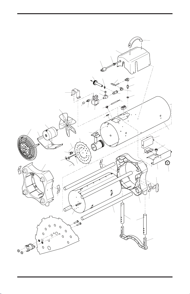
ILLUSTRATED PARTS BREAkDOWN
37
38
40
39
37
23
36
33
31
Detail A
125 Models
Detail B
85 Models
Detail A
Detail B
26
24
25
29
27
32
28
30
4
2
3
42
43
1
22
16
15
14
13
18
12
20
19
17
10
11
10
9
8
7
6
5
35
34
21
38
41
44
www.desatech.com
119143-01A14

PARTS LIST
This list contains replaceable parts used in your heater. When ordering parts, follow the
instructions listed under Replacement Parts on page 11 of this manual.
KEY
NO. PART NO. DESCRIPTION QTY.
1 118476-01 Handle • • • • • • • 1
2 118472-01 Control Box • • • • • • • 1
3 M11143-2 Strain Relief Bushing • • • • • • • 1
4 098219-42 Power Supply Cord Assembly • • • • • • • 1
5 100145-03 Fuel Tube • • • • • • • 1
6 118796-01 Female Compression Fitting • • • • • • • 1
7 114159-05 Ball Valve Assembly • • • 1
114159-03 Ball Valve Assembly • • • • 1
8 113810-01 Ball Valve Knob Insert • • • • • • • 1
9 118773-01 Ball Valve Knob • • • • • • • 1
10 113870-01 Elbow Fitting • • • • • • • 2
11 116981-01 Female Cap Fitting • • • • • • • 1
12 097155-01 Control Valve • • • • • • • 1
13 113869-01 Coupling Fitting • • • • • • • 1
14 097809-04 Male Fitting • • • • • • • 1
15 113794-01 Valve Nut • • • • • • • 1
16 078978-03 Sleeve Cap • • • • • • • 1
17 119401-01 Terminal Block • • • • • • • 1
18 118506-01 Heat Shield • • • • • • • 1
19 113867-01 Hi-Lo Mini Ignitor • • • • • • • 1
20 114150-01 Steel Spacer • • • • • • • 1
21 118802-01 Printed Circuit Board Support • • • • • • • 3
22 113875-02 Relay Assembly • • • • • • • 1
23 118473-01 Fan Guard • • • • • • • 1
24 118482-01 Motor Mount • • • • • • • 1
25 113860-02 Motor Assembly • • • • • • • 1
26 113881-01 Fan 7" • • • 1
114160-01 Fan 8" • • • • 1
27 097805-03 Ignitor • • • • 1
097805-04 Ignitor • • • 1
28 097806-03 Ignitor Cable • • • • • • • 1
29 101481-04 Thermal Limit Switch • • • 1
101481-13 Thermal Limit Switch • • • • 1
30 098249-01 Nut • • • • • • • 1
31 118497-01 Rear Plate • • • • 1
118497-03 Rear Plate • • • 1
32 104146-05 Thermocouple • • • • • • • 1
33 118514-01 Burner Assembly • • • 1
118765-02 Burner Assembly • • • • 1
34 118685-02 Injector • • • 1
118685-03 Injector • • • • 1
35 100146-01 Female Elbow • • • • • • • 1
36 119496-02 Shell (Black) • • • • • • • 1
37 118471-01 End Cap • • • • • • • 2
38 119459-01 Hold Down Bracket • • • • • • • 4
39 119497-02 Combustion Chamber • • • • • • • 1
40 118477-01 Steel Tube • • • • • • • 4
41 118475-01 Cord Cleat • • • • • • • 2
42 118478-01 Foot Leg • • • • • • • 2
43 118474-01 Foot • • • • • • • 1
44 119631-01 Nut • • • • • • • 1
M9900-199 Wire Assembly, Black • • • • • • • 1
M9900-200 Wire Assembly, White • • • • • • • 1
101480-14 Wire Assembly, Blue • • • • • • • 1
118774-01 Hose and Regulator Assembly • • • 1
118774-02 Hose and Regulator Assembly • • • • 1
118687-01 Operation Decal • 1
118687-03 Operation Decal • • • • • • 1
119144-02 Model Data Decal • • • 1
119144-03 Model Data Decal • • • • 1
119146-01 Wiring Decal • • • • • • • 1
119143-01A 15
PARTS AVAILABLE - NOT SHOWN
www.desatech.com
TB111
TB114
TB112
ILLUSTRATED PARTS BREAkDOWN
34
33
42
43
1
36
35
33
22
32
31
5
30
Detail A
Detail A
25
23
24
28
26
27
29
12
13
14
17
11
10
9
19
18
4
6
7
8
3
2
15
16
21
20
41
40
39
38
37
18
34
44
www.desatech.com
119143-01A16
PARTS LIST
This list contains replaceable parts used in your heater. When ordering parts, follow the
instructions listed under Replacement Parts on page 11 of this manual.
KEY
NO. PART NO. DESCRIPTION QTY.
1 118476-01 Handle • • • 1
2 118770-01 Control Box • • • 1
3 M11143-2 Strain Relief Bushing • • • 1
4 098219-42 Power Supply Cord Assembly • • • 1
5 118767-01 Fuel Tube • • • 1
6 100146-01 Female Elbow • • • 1
7 118685-04 Injector • • • 1
8 M50114-02 Male Elbow • • • 1
9 114159-04 Ball Valve Assembly • • • 1
10 113810-01 Ball Valve Knob Insert • • • 1
11 118773-02 Ball Valve Knob • • • 1
12 098276-01 Plug • • • 1
13 118768-01 Street Tee • • • 1
14 098201-01 Solenoid Valve • • • 1
15 097809-04 Male Fitting • • • 1
16 078978-03 Sleeve Cap • • • 1
17 118766-01 Solenoid Valve Bracket • • • 1
18 113944-01 Thermostat Assembly • • • 1
19 119401-01 Terminal Block • • • 1
20 099123-01 Thermobulb Clip • • • 1
21 M50104-02 Shorty Bushing • • • 1
22 118473-01 Fan Guard • • • 1
23 118482-01 Motor Mount • • • 1
24 113941-02 Motor Assembly • • • 1
25 113950-01 Fan • • • 1
26 097805-03 Ignitor • • • 1
27 097806-03 Ignitor Cable • • • 1
28 101481-05 Thermal Limit Switch • • • 1
29 098249-01 Nut • • • 1
30 118497-01 Rear Plate • • • 1
31 118765-02 Burner Assembly • • • 1
32 119496-03 Shell (Black) • • • 1
33 118471-01 End Cap • • • 2
34 119459-01 Hold Down Bracket • • • 4
35 119497-03 Combustion Chamber • • • 1
36 118477-02 Steel Tube • • • 4
37 110287-01 DSI Control • • • 1
38 097776-01 Universal Bushing • • • 1
39 113961-01 Thermostat Knob • • • 1
40 118919-01 Heat Shield • • • 1
41 118475-01 Cord Cleat • • • 2
42 118478-02 Foot Leg • • • 2
43 118474-01 Foot • • • 1
44 119631-01 Nut • • • 1
M16841-80 Wire Assembly, White • • • 1
M9900-170 Wire Assembly, Black • • • 1
101480-15 Wire Assembly, Blue • • • 1
116774-03 Hose and Regulator Assembly • • • 1
118687-04 Operation Decal • • • 1
119144-04 Model Data Decal • • • 1
119146-02 Wiring Decal • • • 1
099504-08 Warning Decal • • • 1
110267-02 DSI Control Harness • • • 1
119143-01A 17
PARTS AVAILABLE - NOT SHOWN
www.desatech.com

WARRANTy AND REPAIR SERVICE
kEEP THIS WARRANTy
Model
Serial No.
Date of Purchase
LIMITED WARRANTIES FOR NEW AND FACTORy
RECONDITIONED PRODUCTS
New Products: DESA Heating Products warrants this heater and any parts thereof, to be free of defects in
materials and workmanship for one (1) year from the date of rst purchase, when operated and maintained
in accordance with the manufacturer's instructions. These warranties are extended only to the original retail
purchaser, when proof of purchase is provided.
Factory Reconditioned Heaters: DESA Heating Products warrants this factory reconditioned heater and any
parts thereof, to be free of defects in materials and workmanship for thirty (30) days from the date of rst
purchase, when operated and maintained in accordance with the manufacturer's instructions. These warranties are extended only to the original retail purchaser, when proof of purchase is provided.
These warranties cover only the cost of parts and labor required to restore the product to proper operating
condition. Transportation and incidental costs associated with warranty repairs are not reimbursable under
this warranty.
Warranty service is available only through authorized dealers and service centers.
This warranty does not cover defects resulting from misuse, abuse, negligence, accidents, lack of proper
maintenance, normal wear, alteration, modication, tampering, contaminated fuels, repair using improper
parts or repair by anyone other than an authorized dealer or service center. Routine maintenance is the
responsibility of the owner.
THIS EXPRESS WARRANTY IS GIVEN IN LIEU OF ANY OTHER WARRANTY EITHER EXPRESSED
OR IMPLIED, INCLUDING WARRANTIES OF MERCHANTABILITY AND FITNESS FOR A PARTICULAR
PURPOSE.
DESA Heating Products assumes no responsibility for indirect, incidental or consequential damages. Some
states do not allow the exclusion or limitation of incidental or consequential damages or limitations or exclu-
sions may not apply to you. This limited warranty gives you specic legal rights and you may also have other
rights which vary from state to state.
We reserve the right to amend these specications at any time without notice. The only warranty applicable
is our standard written warranty. We make no other warranty, expressed or implied.
WARRANTy SERVICE
Should your heater require service, return it to your nearest authorized service center. Proof of purchase
must be presented with the heater. The heater will be inspected. A defect may be caused by faulty materials
or workmanship. If so, DESA Heating Products will repair or replace the heater without charge.
REPAIR SERVICE
Return your heater to your nearest authorized service center. Repairs not covered by the warranty will be
billed at standard prices. Each Service Center is independently owned and operated. We reserve the right
to amend these specications at any time without notice. When writing, always include model number and
serial number. For information, write:
2701 Industrial Drive
P.O. Box 90004
Bowling Green, KY 42102-9004
82 Akron Road
Toronto, Ontario
M8W 1T2
119143-01
Rev. A
06/06

CALENTADOR DE AIRE FORZADO DE PROPANO O GAS LP
PARA CONSTRUCCIÓN
MANUAL DEL PROPIETARIO
MODELOS DE 55,000 BTU, TB100, TB104, TB106, TB110
MODELOS DE 85,000 BTU, TB102, TB111, TB114
125,000 BTU TB101, TB105, TB107, TB112
170,000 BTU TB103, TB108, TB113
IMPORTANTE: lea y comprenda este manual antes de
ensamblar, encender o dar servicio al calentador. El uso
inadecuado del calentador puede causar lesiones graves. Conserve este manual para referencias futuras.
ADVERTENCIA GENERAL DE PELIGRO: el incumplimiento de las precauciones e instrucciones proporcionadas con este calentador puede causar la muerte, lesiones
físicas graves y pérdidas o daños a la propiedad ocasionados por incendios, explosiones, quemaduras, asxia, intoxicación con monóxido de carbono y/o electrocución.
Únicamente las personas que puedan entender y seguir las
instrucciones deberán usar o dar servicio a este calentador.
Si necesita ayuda o información sobre el calentador, por
ejemplo, un manual de instrucciones, etiquetas, etc.,
comuníquese con el fabricante.
Para obtener mayor información, visite el sitio www.desatech.com
Guarde este manual para futuras referencias.

Información de seguridad .................................... 2
Identicación del producto ................................... 3
Desempaque ....................................................... 4
Ensamble............................................................. 4
Teoría de funcionamiento .................................... 4
Suministro de propano ........................................ 5
Ventilación ........................................................... 5
Instalación ........................................................... 5
Funcionamiento ................................................... 6
Almacenamiento .................................................. 7
TABLA DE CONTENIDO
INFORMACIÓN DE SEGURIDAD
ADVERTENCIA: este producto contiene y/o genera químicos
reconocidos por el estado de California como causantes de cáncer
o de defectos de nacimiento, u
otros daños reproductivos.
ADVERTENCIA: peligro de
incendio, quemaduras, inhalación
y explosión. Mantenga los combustibles sólidos, como materiales
de construcción, papel o cartón, a
una distancia segura del calentador
según se recomienda en las instrucciones. Nunca use el calentador en
áreas en las que hayan, o puedan
haber, combustibles volátiles o que
se acumulen en el aire, o bien, productos como gasolina, solventes,
disolvente de pintura, partículas de
polvo o químicos desconocidos.
ADVERTENCIA: no se debe
usar en residencias ni en vehículos recreativos.
El calentador fue diseñado y aprobado para su
uso como calentador para construcción bajo
la norma de calentadores para construcción
ANSI Z83.7•CGA 2.14-2000. El propósito de los
calentadores para construcción es proporcionar
calefacción temporal a edicios en construcción,
remodelación o reparación. Cuando se usa co-
rrectamente, el calentador proporciona calefacción
económica y segura. Los productos de combustión se ventilan al área que se está calentando.
No podemos prever todos los usos que se les
pueden dar a nuestros calentadores. Consulte
con la autoridad local de seguridad contra
incendios en caso que tenga alguna pregunta acerca del uso de calentadores.
www.desatech.com
Mantenimiento ..................................................... 7
Procedimientos de servicio.................................. 8
Especicaciones .................................................. 9
Diagramas de cableado..................................... 10
Piezas de repuesto .............................................11
Servicio técnico ..................................................11
Publicaciones de servicio ...................................11
Accesorios ..........................................................11
Clasicación ilustrada de piezas y lista de piezas ....12
Garantía y servicio de reparación...................... 18
Otras normas rigen el uso de gases combustibles y productos que producen calor para usos
especícos. Las autoridades locales pueden
informarle acerca de éstas.
Intoxicación con monóxido de carbono: el mo-
nóxido de carbono afecta más a unas personas
que a otras. Los primeros signos de intoxicación
con monóxido de carbono son semejantes a
los de la gripe, con dolor de cabeza, mareo o
náusea. Si usted presenta estos síntomas, es
posible que el calentador no esté funcionando
correctamente. ¡Respire aire fresco inmediata-
mente! Haga que le den servicio al calentador.
Propano o gas LP: el propano o gas LP es inodo-
ro. Al propano o gas LP se le agrega un agente
que tiene olor. El olor le ayuda detectar las fugas
de propano o gas LP. Sin embargo, el olor que se
añade al propano o gas LP puede desvanecerse.
Es posible que haya propano o gas LP en el
entorno aunque no haya ningún olor.
Asegúrese de leer y comprender todas las
advertencias. Conserve este manual como
referencia. Es su guía para la operación segura
y correcta de este calentador.
1.
Instale y use el calentador con cuidado. Siga todas
las ordenanzas y los códigos locales. A falta de
reglamentos y códigos locales, consulte la Norma
de almacenamiento y manejo de gas licuado de
petróleo, ANSI/NFPA 58 y el Código para instalación de gas natural y propano, CSA B149.1. Estos
proporcionan instrucciones acerca del almacenamiento y manejo seguro del propano.
2. Use solamente el voltaje y la frecuencia
especificados en la placa del modelo.
Las conexiones eléctricas y de tierra del
calentador deberán hacerse de acuerdo al
Código eléctrico nacional, ANSI/NFPA 70,
o al Código eléctrico canadiense, parte 1.
3.
Instrucciones para la conexión eléctrica a
tierra: este aparato está equipado con una
clavija de tres patas (con conexión a tierra)
para protegerlo contra descargas eléctricas,
y se tiene que conectar directamente a un enchufe de pared o un cable de extensión de tres
ranuras conectado a tierra correctamente.
4. Este producto ha sido aprobado para su
uso en el estado de Massachusetts.
5. Para uso en interiores solamente. Proporcione una ventilación adecuada.
119143-01A2

INFORMACIÓN DE
SEGURIDAD Continuación
6. Mantenga el calentador alejado de corrien-
tes fuertes de aire, viento, rocío, lluvia y
goteos de agua.
7. Úsese solamente en áreas bien ventiladas.
Antes de usar el calentador, debe existir
una abertura de cuando menos 0.28 m
cuadrados (3 pies cuadrados) para aire
fresco del exterior por cada 105,500 k/j
(100,000 BTU/h) de clasicación.
8. No use el calentador en el exterior ni en
viviendas habitadas.
9.
No use el calentador en salas o dormitorios.
10. Mantenga el área en dónde se localiza el
aparato despejada y libre de materiales
combustibles, gasolina, disolvente de pintura y otros vapores y líquidos inamables. El
polvo es combustible. No use el calentador
en áreas con alto contenido de polvo.
11. Si este calentador está equipado con ter-
mostato. El calentador puede empezar a
funcionar en cualquier momento.
12. Antes de cada uso, verique si el calentador
ha sufrido algún daño. No use un calentador
dañado.
13. Use solamente el montaje de propano o
gas LP para la extracción de vapores.
14. Mantenga los tanques de propano por
debajo de los 38 ºC (100 °F).
15. No use el calentador en un sótano ni debajo
del nivel del suelo. El propano o gas LP es
más pesado que el aire. Si se produce una
fuga, el propano o gas LP se asentará en
el nivel más bajo posible.
16. Use sólo el regulador de fábrica y la manguera que se incluyen con el calentador.
17. Revise la manguera antes de cada uso del
calentador. Si la manguera está muy des-
gastada o con roturas, reemplácela con una
manguera especicada por el fabricante
antes de usar el calentador.
18. No altere el calentador. Mantenga el calentador en su estado original.
19.
No use el calentador si éste ha sido alterado.
20.
Mantenga el calentador alejado de los tanques
de propano o gas LP a una distancia de por lo
menos 1.8 m (6 pies). No apunte el calentador
a los tanques de propano o gas LP que se
encuentren a menos de 6.1 m (20 pies).
21. Distancias mínimas del calentador alejado
de los combustibles: enchufe 2.4 m (8 pies),
laterales 0.6 m (2 pies), parte superior 1.8 m
(6 pies), parte posterior 0.6 m (2 pies).
22. Sitúe el calentador en una supercie estable
y nivelada si el calentador está caliente o
en funcionamiento.
23. Evite que los niños y los animales se acerquen al calentador.
119143-01A 3
www.desatech.com
24. Cierre el suministro de propano o gas LP
al calentador y desconéctelo cuando no se
esté usando.
25. Nunca bloquee la entrada de aire (parte
posterior) ni la salida de aire caliente (parte
anterior) del calentador.
26.
Nunca mueva, maneje ni repare un calentador
en funcionamiento caliente o conectado.
27. Nunca conecte conductos a la parte anterior
o posterior del calentador.
28.
Use sólo piezas de repuesto originales. Este
calentador debe usar piezas diseñadas especícamente. No las sustituya ni use piezas genéricas. El uso de piezas de repuesto inadecuadas
puede ocasionar lesiones graves o fatales.
29. N
o utilice este producto sin el conjunto
del soporte y los laterales.
IDENTIFICACIÓN DEL
PRODUCTO
Perilla de ajuste
Botón de
la válvula
de control
de gas
automático
Entrada de
aire (parte
posterior)
Figura 1 - Modelos de 55/85/125,000 BTU/h
Perilla de
ajuste del
factor de
consumo
Entrada de
aire (parte
posterior)
del factor de
consumo
Sujetador
del cordón
Perilla del
termostato
Manija
Sujetador
del cordón
Figura 2 - Modelos de 170,000 BTU/h
Salida de aire
caliente (parte
Manija
anterior)
Soporte
ajustable
Salida de aire caliente
(parte anterior)
Soporte
ajustable

Air For
Combustion
Air For
Heating
1. Retire todos los materiales en los que se
DESEMPAQUE
empacó el calentador para el envío. Conserve los tapones de plástico (colocados
en el conector de entrada del calentador
y en el conjunto de manguera y regulador)
para propósitos de almacenamiento.
2. Saque todas las piezas de la caja.
3. Revise todas las piezas en busca de da-
ños durante el transporte. Si el calentador
está dañado, infórmelo de inmediato al
distribuidor donde lo compró.
ENSAMBLE
IMPORTANTE: no utilice este producto sin el
conjunto del soporte y los laterales.
Manija
Fije la manija a la caja de control con 2 tornillos
(largos) como se muestra en la gura 3.
Soporte de plástico y extensiones laterales
1. Inserte las extensiones laterales en la tapa
del extremo de salida hasta que el oricio
pequeño se alinee con el orificio más
grande, visible desde dentro de la tapa
del extremo de salida (consulte la gura
3). Sujete las extensiones laterales con el
tornillo provisto (cortos).
2. Inserte los extremos del soporte de plástico
dentro de cada extensión lateral y ajuste el
calentador al ángulo deseado. Los tornillos
de los postes pequeños en el soporte de
plástico entrarán a presión dentro de los
oricios en las extensiones laterales.
S
ujetador del cordón
Instale los sujetadores del cordón al lado de la
tapas de los extremos como se muestra en la
gura 3 con los tornillos cortos provistos.
Tapa del
extremo
de salida
Figura 3 - Manija y conjunto del soporte
Poste
pequeño
Tornillo
largos
Manija
Tornillo de sujeción
de la extensión
lateral (cortos)
Extensión lateral
Soporte de plástico
Sujetador
del cordón
Tornillo
cortos
TEORÍA DE FUNCIONAMIENTO
El sistema de combustible: el conjunto de manguera y regulador se ja al suministro del gas pro-
pano. Para los modelos 55/85/125, el gas propano uye a través la válvula de control automático,
la válvula de ajuste de factor de consumo y fuera del inyector. Para el modelo 170, el gas propano
uye a través la válvula solenoide, la válvula de ajuste de factor de consumo y fuera del inyector.
El sistema de aire: el motor hace girar el ventilador. El ventilador empuja aire al interior y alrededor de la
cámara de combustión. Este aire se calienta y proporciona una corriente de aire limpio y caliente.
El sistema de encendido: para los modelos 55/85/125 el encendedor de alto voltaje envía tensión
al encendedor de chispa. Para el modelo 170 el encendedor de chispa directa envía tensión al
encendedor de chispa. El encendedor de chispa hace que arda la mezcla de combustible y aire.
El sistema de control de seguridad: este sistema hace que el calentador se apague si la llama se
apaga. El motor continuará funcionando pero no se producirá calor.
Encendedor de alto voltaje (en modelos 55/85/125) o
encendedor de chispa directa DSI (en modelo 170)
Interruptor de
límite térmico
Salida de
aire caliente
y limpio
(parte
anterior)
Cámara de
combustión
Inyector
Encendedor
de chispa
Aire para
combustión
Figura 4 - Vista transversal de funcionamiento
Ventilador
www.desatech.com
Válvula de control automático (en
modelos 55/85/125 solamente)
Válvula solenoide (en
modelo 170 solamente)
Cable de
alimentación
Entrada de
aire frío (parte
posterior)
Motor
Aire para
calefacción
Conjunto de
manguera y
regulador
119143-01A4

SUMINISTRO DE
PROPANO
El propano o gas LP y el o los tanques de propano o gas LP los debe proveer el usuario.
Use el calentador solamente con un sistema
de suministro con extracción de vapores de
propano o gas LP. Consulte el capítulo 5 de
la Norma para almacenamiento y manejo de
gas licuado de petróleo, ANSI/NFPA 58 y el
Código para instalación de gas natural y de
propano CSA B149.1. La biblioteca local o
el departamento de bomberos deben tener
estos folletos.
La cantidad de propano o gas LP lista para
usarse de los tanques de propano o gas
LP varía. Dos factores determinan esta
cantidad:
1. El volumen de gas propano en el o los
tanques
2. La temperatura del o los tanques
La siguiente tabla muestra el número de tan-
ques de 45 kg (100 libras) que se necesitan
para hacer funcionar este calentador.
Número de tanques
Temperatura Modelos
en la ubicación del tanque 55 85 125/170
superior a -7 °C (20 °F) 1 1 2
-7 °C (20 °F) a -18C (-0 °F) 1 2 3
A temperaturas más bajas se vaporiza menos
gas. Es posible que necesite un tanque más
grande cuando el tiempo esté más frío. El
surtidor de propano o gas LP de su localidad
le ayudará a seleccionar el sistema de suministro apropiado.
tienda las advertencias en la sección Información de seguridad,
en la página 2. Son necesarias
para hacer funcionar este calentador de manera segura. Obedezca todos los códigos locales al
utilizar este calentador.
las tuberías de gas y sus conexiones para saber si hay fugas después de la instalación o reparación.
Nunca use una llama al descubierto
para buscar fugas. Aplique una
mezcla de jabón líquido y agua en
todas las uniones. La formación de
burbujas indicará una fuga. Repare
todas las fugas inmediatamente.
1. Proporcione un sistema de suministro de
2. Instale la conexión de rosca invertida en
VENTILACIÓN
ADVERTENCIA: siga los requisitos mínimos de ventilación
con aire fresco del exterior. Si no
proporciona ventilación de aire
fresco del exterior podría haber
intoxicación con monóxido de carbono. Proporcione una ventilación
adecuada de aire fresco del exterior
antes de encender el calentador.
Asegúrese de que exista una abertura de aire
fresco del exterior de por lo menos 0.28 metros cuadrados (tres pies cuadrados) por cada
105,500 k/j (100,000 BTU/h) de clasicación.
Proporcione aire fresco adicional si se utilizan
más calentadores.
119143-01A 5
www.desatech.com
3. Conecte la manguera al conector de en-
Válvula del
suministro
Tanque de
propano
INSTALACIÓN
ADVERTENCIA: revise y en-
ADVERTENCIA: pruebe todas
propano o gas LP (consulte Suministro de
Propano o gas LP).
el conjunto de manguera y regulador al
los tanques de propano o gas LP. Gire la
conexión de rosca invertida en el sentido
contrario al de las manecillas del reloj
dentro de las roscas del tanque. Apriete
rmemente usando una llave. IMPORTANTE: apriete el regulador con la ventila
orientada hacia abajo. Orientando la ventila hacia abajo se protege el regulador de
daños climáticos.
trada del calentador. Apriete rmemente
usando una llave.
Regulador
Conexión
de rosca
invertida
Conector
del gas
combustible
Figura 5 - Regulador externo con la
ventila apuntando hacia abajo
Al conector de
entrada del
calentador
Manguera
Ventila
(orientada
hacia abajo)

INSTALACIÓN
IMPORTANTE: es posible usar manguera o
tubería adicionales si se requieren. Instale la
manguera o tubería adicional entre el tanque
de propano o gas LP y el regulador. Debe ase-
gurarse de exista un mínimo de 172.4 kPa (25
psig) a la entrada del regulador. Debe usar el
regulador que se incluye con el calentador.
4. Abra lentamente la válvula del suministro de
los tanques de propano o gas LP. Nota: si
no se abre lentamente, la válvula de exceso
de ujo del tanque de propano o gas LP
detendrá el ujo de gas. Si esto ocurre, es
posible que se escuche un chasquido en
el interior del ensamble del regulador. Para
restablecer la válvula de exceso de ujo,
cierre la válvula del suministro de propano
o gas LP y ábrala de nuevo lentamente.
5. Revise todas las conexiones en busca de
fugas.
6. Cierre la válvula del suministro de propano o gas LP.
Botón de la
válvula de gas
Manguera
Figura 6 - Conector de entrada y
manguera (el calentador puede ser
diferente al mostrado en la ilustración)
Continuación
Conector de entrada
FUNCIONAMIENTO
ADVERTENCIA: revise y entienda las advertencias en la sección
Información de seguridad, en la
página 2. Son necesarias para hacer
funcionar este calentador de manera
segura. Obedezca todos los códigos
locales al utilizar este calentador.
PARA ENCENDER EL CALENTADOR
1. Siga toda la información de instalación,
ventilación y seguridad.
2. Sitúe el calentador sobre una supercie
estable y nivelada. Asegúrese de que no
haya corrientes fuertes de aire entrando en
la parte anterior o posterior del calentador.
www.desatech.com
3. Conecte el cable de alimentación del calentador a un cable de extensión con conexión
a tierra de tres patas. El cable de extensión
debe tener por lo menos 1.8 m (6 pies) de
longitud. El cable de extensión debe estar
aprobado por Underwriters Laboratories.
Requisitos de tamaño del cable de extensión
Hasta 15 m (50 pies) de longitud, use cable
de calibre 18 AWG.
De 15.5 a 30.5 m (51 a 100 pies) de longi-
tud, use cable de calibre 16 AWG.
De 30.78 a 61 m (101 a 200 pies) de lon-
gitud, use cable de calibre 14 AWG.
4. Conecte el cable de extensión a un enchufe
con conexión a tierra de tres oricios de
120 V/60 Hz.
5. Abra lentamente la válvula del suministro
de los tanques de propano o gas LP. Nota:
si no se abre lentamente, la válvula de exceso de ujo del tanque de propano o gas
LP detendrá el ujo de gas. Si esto ocurre,
es posible que se escuche un chasquido en
el interior del ensamble del regulador. Para
restablecer la válvula de exceso de ujo,
cierre la válvula del suministro de propano
o gas LP y ábrala de nuevo lentamente.
6. Ajuste la perilla de control de BTU variable
en sentido de las manecillas del reloj total-
mente hasta la posición Bajo.
En modelos 55, 85, 125 solamente
7. Presione y mantenga presionado el botón
de la válvula de gas. El calentador se debe
encender en unos cuantos segundos.
Nota: si el calentador no se enciende, es
posible que la manguera tenga aire en el
interior. Si es así, mantenga presionado
el botón de la válvula de gas y espere 20
segundos. Suelte el botón de la válvula
de gas y espere 20 segundos para que el
combustible que no se quemó salga del
calentador. Repita el paso 6.
8. Una vez que el calentador se encienda, espere 30 segundos. Esto activará el sistema
de control automático. Suelte el botón de
la válvula de control de gas.
En modelo 170 solamente
9. Ajuste el termostato a la posición deseada.
Si el calentador no enciende, es posible
que el termostato tenga seleccionado un
valor muy bajo. Gire la perilla del termostato hacia el valor más alto para encender
el calentador. Nota: si el calentador no
enciende, desconecte el calentador. Espere diez segundos para que el control
119143-01A6

FUNCIONAMIENTO
Continuación
de seguridad se restablezca, conecte el
calentador e intente nuevamente.
Todos los modelos
10. Cuando el quemador permanezca encendido, ajuste el calentador al nivel de
temperatura deseada girando la perilla
de control de BTU variable en sentido
contrario al de las manecillas del reloj. Si el
quemador se apaga, cierre el gas. Gire la
perilla de BTU variable completamente en
el sentido de las manecillas del reloj hasta
la posición más baja. Revise el suministro
de combustible. Si dispone del combustible
adecuado, vuelva encender el calentador
comenzando con el paso 1.
PARA APAGAR EL CALENTADOR
1. Cierre rmemente la válvula del suministro
de propano en los tanques de propano o
gas LP.
2. Espere unos cuantos segundos. El calentador quemará el gas remanente en las
mangueras de suministro.
3. Desenchufe el calentador.
PARA VOLVER A ENCENDER EL
CALENTADOR
Si el control de seguridad detiene el ujo de
gas al calentador, el motor continuará fun-
cionando.
1. Desenchufe el calentador.
2.
Espere diez segundos. Conecte el calentador.
Si el calentador no se vuelve a encender
A. Verique las válvulas de suministro (en el
tanque de propano o gas LP). Asegúrese
de que estén abiertas.
B. Revise el nivel de combustible de los
tanques de propano o gas LP. Si el nivel
de combustible es muy bajo, póngase en
contacto con su proveedor local de propano o gas LP.
Si el calentador sigue sin encender, póngase en
contacto con su centro local de servicio.
ALMACENAMIENTO
PRECAUCIÓN: desconecte el
calentador del(de los) tanque(s)
de suministro de propano.
1. Guarde los tanques de propano o gas LP
de forma segura. Consulte el capítulo 5 de
la Norma para almacenamiento y manejo
de gas licuado de petróleo, ANSI/NFPA 58
y el
Código para instalación de gas natural
y de propano CSA B149.1
códigos locales.
2. Coloque tapones de plástico sobre las
conexiones de latón en el conector de
entrada del calentador y en el conjunto de
manguera y regulador.
3. Guárdelo en un lugar seco, limpio y seguro. No guarde el conjunto de manguera y
regulador en el interior de la cámara de
combustión del calentador.
4. Siempre revise el interior del calentador
cuando lo saque del lugar de almacenamiento. Los insectos y animales pequeños
pueden haber introducido cuerpos extraños
en el calentador. Mantenga el interior del
calentador libre de objetos combustibles y
ajenos.
. Siga todos los
MANTENIMIENTO
ADVERTENCIA: nunca intente reparar un calentador mientras
esté enchufado, conectado al
suministro de propano, esté funcionando o esté caliente. Pueden
ocurrir quemaduras graves y
electrocución.
1. Mantenga el calentador limpio. Limpie el
calentador anualmente o según sea necesario para retirar el polvo y los residuos.
Si el calentador está sucio o con polvo,
límpielo con un paño húmedo.
2. Inspeccione al calentador antes de cada
uso. Revise las conexiones en busca de
fugas. Aplique una mezcla de jabón líquido
y agua en todas las conexiones. La formación de burbujas indicará una fuga. Repare
todas las fugas inmediatamente.
3. Inspeccione el conjunto de manguera y
regulador antes de cada uso. Si la man-
guera está muy desgastada o con roturas,
reemplácela.
4. Haga que una agencia de servicio calicada inspeccione el calentador anualmente.
5. Mantenga el interior del calentador libre de
objetos combustibles y ajenos.
119143-01A 7
www.desatech.com

PROCEDIMIENTOS DE
SERVICIO
ADVERTENCIA: nunca intente reparar un calentador mientras
esté enchufado, conectado al
suministro de propano, esté funcionando o esté caliente. Pueden
producirse quemaduras graves
y electrocución.
LIMPIEZA DEL VENTILADOR
Limpie el ventilador cada 500 horas de funcionamiento o según sea necesario.
1. Retire los tornillos de la cubierta superior
utilizando una llave para tuercas de 5/16" o
un destornillador Phillips (punta de cruz).
2. Retire la cubierta superior.
3. Desconecte los 2 cables negros del motor
del bloque de terminales debajo de la cubierta superior. Asegúrese de desconectar
sólo los cables que provienen del motor.
4. Retire el resguardo del ventilador de la parte
posterior del calentador. El resguardo del
ventilador sale a presión de la cubierta.
5. Acceda al interior de la parte posterior de la
cubierta del calentador. Cuidadosamente,
tire de los cables del motor a través del
oricio en el soporte. Nota: tire de los
cables a través del oricio, uno a la vez.
6. Quite los tornillos que sujetan el montaje
del motor a la cubierta. Use un destorni-
llador Phillips (punta de cruz) o llave para
tuercas de 5/16".
7. Cui dado same nte, jale el motor y el
ventilador hacia afuera de la cubierta.
IMPORTANTE: tenga cuidado para no
dañar el ventilador. No coloque el motor
y el ventilador en el suelo con el peso
descansando en el ventilador. Esto podría
dañar la inclinación del ventilador.
8. Gire el motor y el ventilador. Coloque el
motor y ventilador dentro de la cubierta al
revés. Nota: el motor debe entrar primero
a la cubierta (consulte la gura 8).
9. Alinee los oricios de montaje de la parte
posterior de la cubierta con los primeros
orificios de cada lado del montaje del
motor (consulte la gura 8). Nota: cuando
los oricios estén alineados, el ventilador
deberá estar fuera de la cubierta.
10. Mientras sujeta los tornillos de montaje, acceda cuidadosamente a la parte posterior
del calentador a través de las aspas del
ventilador. Tenga cuidado de no dañar la
inclinación del ventilador. Inserte el tornillo
través del montaje del motor y la cubierta.
www.desatech.com
Con la otra mano, je el tornillo apretándolo con los dedos. Repita el proceso para
el otro oricio de montaje.
11. Use una llave hexagonal de 1/8" para
aojar el tornillo de jación que sujeta el
ventilador al eje del motor (consulte la
gura 9, en la página 9).
12. Saque el ventilador del eje del motor.
Cubierta
superior
Bloque de
terminales
Orificio en
el soporte
Motor
Soporte de
montaje del motor
Figura 7 - Desmontaje del ventilador y motor
Ventilador
Figura 8 - Ventilador y motor al revés
Soporte de
montaje del motor
para limpieza
119143-01A8

A
20.
PROCEDIMIENTOS DE
SERVICIO Continuación
13. Limpie el ventilador utilizando un trapo suave
humedecido con solvente para limpieza.
14. Seque completamente el ventilador.
15.
Vuelva colocar el ventilador en el eje del mo-
tor. Coloque el tornillo de jación en la parte
plana del eje. Consulte la tabla en la gura
10 para obtener la distancia al centro del
ventilador desde el extremo del eje del motor.
Apriete el tornillo de jación rmemente de
0.46 a 0.58 kgf·m (40 a 50 pulgadas-libra).
16. Quite los tornillos que sujetan el montaje
del motor a la cubierta.
17. Tire del motor y ventilador para quitarlos
de la cubierta. Gire el motor y el ventilador.
Vuelva colocarlos cuidadosamente en la
cubierta. Nota: el ventilador debe entrar
primero a la cubierta.
18. Alinee los oricios de montaje de la cubierta con los oricios de montaje del motor.
Vuelva a colocar 4 tornillos a través de la
cubierta y montaje del motor.
19. Pase los cables del motor a través del
oricio en la parte inferior de la cubierta
(consulte la gura 7, en la página 8).
Tornillo de
Eje del
motor
Núcleo
fijación
Ventilador
Motor
Tornillo de
fijación
www.desatech.com
Ventilador
Eje del
Figura 9 - Identificación del ventilador,
eje del motor y tornillo de fijación
Modelo
125
170 6.4 mm (0.25")
* Depender de
eje del motor
Figura 10 - Sección transversal del ventilador
119143-01A 9
Distancia A
55 4.8 mm (0.19")
85
0.5" (12.7 mm)* o
0.9" (22.9 mm)*
0.5" (12.7 mm)* o
0.9" (22.9 mm)*
motor
Vuelva a conectar los cables a los mismos
postes en el bloque de terminales como fue-
ron desconectados en el paso 3, en la página
8 (consulte la gura 7, en la página 8).
21. Vuelva a colocar la cubierta superior.
22. Vuelva colocar el resguardo del ventilador.
ESPECIFICACIONES
Todos los modelos
• Propano o gas LP
• Presión del suministro de gas al regulador:
Máx: presión de botella, mín: 172.4 kPa
(25 psig)
• Presión del suministro de gas a la salida del
regulador:
137.9 kPa (20 psig)
•
Electricidad de entrada: 120V, 60 Hz, 1Ø, 3a
• Encendido de chispa directa
• Clasificación de temperatura ambiente
mínima: -17.8 °C (0 °F)
Modelos de 55,000 BTU/h
• 8.8 - 16.1 kW (30 - 55,000 BTU/h)
• Consumo de combustible:
0.70 - 1.28 kg/h (1.4 - 2.6 libras/h)
• Control principal de la llama:
Válvula de gas operada con termopar
• Salida de aire caliente: 8.49 m3/min (300
CFM)
Modelos de 85,000 BTU/h
• 14.6 - 25.0 kW (50 - 85,000 BTU/h)
• Consumo de combustible:
1.04 - 1.77 kg/h (2.3 - 3.9 libras/h)
• Control principal de la llama:
Válvula de gas operada con termopar
• Salida de aire caliente: 9.91 m3/min (350
CFM)
Modelos de 125,000 BTU/h
• 21.9 - 36.6 kW (75 - 125,000 BTU/h)
• Consumo de combustible:
1.59 - 2.63 kg/h (3.5 - 5.8 libras/h)
• Control principal de la llama:
Válvula de gas operada con termopar
• Salida de aire caliente: 9.91 m3/min (350
CFM)
Modelos de 170,000 BTU/h
• 36.6 - 49.8 kW (125 - 170,000 BTU/h)
• Consumo de combustible:
2.63 - 3.6 kg/h (5.8 - 7.9 libras/h)
• Control principal de la llama:
Recticación de ama del encendedor de
chispa directa DSI
• Salida de aire caliente: 12.74 m3/min (450
CFM)

DIAGRAMAS DE CABLEADO
Electrode/Electrodo/
Électrode
Orange**/
Naranja**/
Orange**
CONNECTION DIAGRAM/
DIAGRAMA DE CONEXIONES/
SCHÉMA DE CONNEXION
Green/Verde/Vert
• If any original wiring as supplied with the heater must be replaced, it must be replaced with type
AWG 105° C wire or its equivalent except as indicated (*Type SF2-200. **UL Style 3257 250° C)
• Si es necesario reemplazar algún cable suministrado originalmente con el calentador, éste se debe
reemplazar con cable tipo AWG 105° C o su equivalente, excepto cuando se indica locontrario
(*Tipo SF2-200. **UL Style 3257 250° C)
• Si le câblage original fourni avec l'appareil de chauffage doit être remplacé, faites-le avec du câble de
type AWG 105° C ou son équivalent, sauf indication contraire (*Type SF2-200. **UL Style 3257 250° C)
High Limit Switch/
Interruptor de
límite alto/
Commutateur de
limite supérieure
Gas Valve/
Válvula de gas/Vanne de gaz
Green/
Verde/
Vert
Green/Verde/Vert
Motor/
Moteur
Flame Control/
Control de llama/
Contrôle de
la flamme
Line/Línea/Ligne
Neut/Neutral/Neutre
Valve/Válvula/Vanne
Ground/Tierra/Masse
White/Blanco/Blanc
White/
Blanco/
Blanc
White/Blanco/Blanc
Blue*/Azul*/Bleu*
Blue*/Azul*/Bleu*
Blue*/
Azul*/
Bleu*
Black/Negro/Noir
Black/Negro/Noir
Black/Negro/
Noir
Black/
Negro/
Noir
Black/Negro/Noir
Thermostat/
Termostato
Chassis Ground/
Conexión a tierra
del chasis/Masse
Chassis Ground/
Conexión a tierra
del chasis/Masse
Chassis Ground/
Conexión a tierra
del chasis/Masse
Line Cord/
Cable de alimentaión/
Cordon d'alimentation
Black** or Orange**/
Negro** o Naranja**/
Noir** ou orange**
L1
L2
White/Blanco/
Blanc
Blue*/Azul*/Bleu*
Blue*/Azul*/Bleu*
Blue/Azul/Bleu
White/Blanco/
Blanc
White/Blanco/Blanc
Black/
Negro/Noir
Black/Negro/Noir
Black/Negro/Noir
Black/Negro/Noir
Green/
Verde/
Vert
Orange/
Naranja
Orange/
Naranja
Orange/
Naranja
Orange/
Naranja
Thermocouple/Termopar
CONNECTION DIAGRAM/DIAGRAMA DE CONEXIONES/
DIAGRAMME DE CONNEXION
SCHEMATIC DIAGRAM/DIAGRAMA ESQUEMÁTICO/
DIAGRAMME DE CIRCUIT
Relay/Relé/Relais
Motor/
Moteur
Ignitor/
Encendedor/
Allumeur
High-Limit Switch/
Interruptor de
límite alto/
Commutateur de
limite supérieure
• If any original wiring as supplied with the heater must be replaced, it must be replaced with type AWG 105° C
wire or its equivalent except as indicated (*Type SF2-200. **UL Style 3257 250° C)
• Si es necesario reemplazar algún cable suministrado originalmente con el calentador, éste se debe reemplazar con
cable tipo AWG 105° C o su equivalente, excepto cuando se indica lo contrario (*Tipo SF2-200. **UL Style 3257 250° C)
* Si le câblage fourni avec l'appareil de chauffage doit être remplacé, faites-le avec du câble de type AWG 105° C
ou son équivalent, sauf indication contraire (*Type SF2-200. **UL Style 3257 250° C)
Line Cord/
Cable de línea/
Cordon électrique
Motor/
Moteur
High Limit Switch/
Interruptor de límite alto/
Interrupteur de
limite supérieure
White/Blanco/Blanc
Black/Negro/Noir
115V
60HZ
Gas
Valve
Relay/
Relé/
Relais
Thermocouple/
Termopar
Green/Verde/Vert
L1
L2
Ignitor/
Encendedor/
Allumeur
Válvula de gas/
Robinet de gaz
Electrode/Electrodo/
Électrode
Electrode/Electrodo/
Électrode
Modelos de 55,000, 85,000 y 125,000 BTU/h
Modelos de 170,000 BTU/h
www.desatech.com
119143-01A10

PIEZAS DE REPUESTO
ADVERTENCIA: use sólo
piezas de repuesto originales.
Este calentador debe usar piezas
diseñadas especícamente. No
las sustituya ni use piezas genéricas. El uso de piezas de repuesto
inadecuadas puede ocasionar
lesiones graves o fatales. Esto
también protegerá la cobertura
de su garantía para piezas reemplazadas bajo garantía.
PIEZAS CON GARANTÍA
Comuníquese con los distribuidores autori-
zados de este producto. Si ellos no pueden
suministrar las piezas de repuesto originales,
comuníquese con la central de piezas más
cercana o llame al Departamento de servicio
técnico de DESA Heating Products al 1-866672-6040. Cuando llame a DESA Heating
Products, tenga listo:
• su nombre
• su dirección
• los números de modelo y de serie de su
calentador
• la falla del calentador
• la fecha de compra
En la mayoría de los casos, le pediremos que
devuelva la pieza a la fábrica.
PIEZAS SIN GARANTÍA
Comuníquese con los distribuidores autori-
zados de este producto. Si ellos no pueden
suministrar piezas de repuesto originales,
comuníquese con la central de piezas más
cercana o llame a DESA Heating Products
al 1-866-672-6040 para obtener información
de referencias Cuando llame a DESA Heating
Products, tenga listo:
• el número del modelo de su calentador
• el número de la pieza de repuesto
SERVICIO TÉCNICO
Es posible que tenga más preguntas acerca
de este calentador. Si es así, comuníquese
con el Departamento de servicio técnico de
DESA Heating Products al 1-866-672-6040.
Al llamar tenga a la mano los números de
modelo y serie de su calentador.
También puede visitar el sitio web de servicio técnico de DESA Heating Products en
www.desatech.com.
PUBLICACIONES DE
SERVICIO
Puede comprar un manual de servicio por
$5. Escriba el cheque a nombre de DESA
Heating Products. Envíe su orden a DESA
Heating Products (dirección al reverso de la
página). Asegúrese de incluir el número de
modelo del calentador.
ACCESORIOS
Adquiera accesorios y piezas con su distribuidor o centro de servicio más cercano. Si
ellos no pueden suministrar un accesorio o
pieza de repuesto original, comuníquese con
la Central de piezas más cercana listada en
el folleto de Centros de servicio autorizados
provisto por separado, o bien, llame a DESA
Heating Products al 1-866-672-6040. También
puede escribir a la dirección que se encuentra
en la última página de este manual.
Conexión de combustible de gas:
LPA4020
Adaptador de rosca invertida con válvula de
exceso de ujo.
119143-01A 11
www.desatech.com

CLASIFICACIÓN ILUSTRADA DE PIEZAS
41
42
36
40
39
38
36
29
35
32
22
16
15
14
13
18
12
20
19
17
10
11
30
Detail A
Detail A
25
24
23
28
26
31
27
10
9
8
7
6
5
34
33
43
4
2
3
21
1
37
37
MODELOS DE 55,000 BTU/H, TB100, TB104, TB106 Y TB110
Detalle A
Detalle A
www.desatech.com
119143-01A12

LISTA DE PIEZAS
MODELOS DE 55,000 BTU/H
Esta lista contiene las piezas reemplazables utilizadas en el calentador. Al hacer un pedido de piezas, siga las instrucciones enumeradas en Piezas de repuesto en la página 11 de este manual.
N° DE
N°
PARTE DESCRIPCIÓN
1 118476-01 Manija • • • • 1
2 118472-01 Caja de control • • • • 1
3 M11143-2 Buje para atenuar deformaciones • • • • 1
4 098219-42 Conjunto de cables de la fuente de alimentación • • • • 1
5 100145-03 Tubo de combustible • • • • 1
6 118796-01 Conexión de compresión hembra • • • • 1
7 114159-05 Conjunto de válvula de bola • • • • 1
8 113810-01 Acoplamiento de la perilla de la válvula de bola • • • • 1
9 118773-01 Perilla de la válvula de bola • • • • 1
10 113870-01 Conexión de codo • • • • 2
11 116981-01 Tapón de conexión hembra • • • • 1
12 097155-01 Válvula de control • • • • 1
13 113869-01 Conexión de acoplamiento • • • • 1
14 097809-04 Conexión macho • • • • 1
15 113794-01 Tuerca de la válvula • • • • 1
16 078978-03 Casquillo tapón • • • • 1
17 119401-01 Bloque de terminales • • • • 1
18 118506-01 Protector de calor • • • • 1
19 113867-01 Encendedor miniatura Alto-Bajo • • • • 1
20 114150-01 Espaciador de acero • • • • 1
21 118802-01 Soporte de placa de circuito impreso • • • • 3
22 113875-02 Conjunto de relé • • • • 1
23 118780-01 Conjunto de parrilla del motor • • • • 1
24 113880-02 Conjunto de motor • • • • 1
25 113881-01 Ventilador • • • • 1
26 097805-04 Encendedor • • • • 1
27 097806-03 Cable del encendedor • • • • 1
28 101481-12 Interruptor de límite térmico • • • • 1
29 098249-01 Tuerca • • • • 1
30 118497-02 Placa posterior • • • • 1
31 104146-05 Termopar • • • • 1
32 118514-01 Conjunto de quemador • • • • 1
33 118685-01 Inyector • • • • 1
34 100146-01 Codo hembra • • • • 1
35 119496-01 Cubierta (Negra) • • • • 1
36 118471-01 Tapa del extremo • • • • 2
37 119459-01 Soporte a presión • • • • 4
38 119497-01 Cámara de combustión • • • • 1
39 118477-03 Tubo de acero • • • • 4
40 118475-01 Sujetador del cordón • • • • 2
41 118478-03 Lateral del soporte • • • • 2
42 118474-01 Soporte • • • • 1
43 119631-01 Tuerca • • • • 1
M9900-199 Conjunto de cables, negro • • • • 1
M9900-200 Conjunto de cables, blanco • • • • 1
101480-14 Conjunto de cables, azul • • • • 1
118774-04 Conjunto de manguera y regulador • • • • 1
118687-01 Etiqueta adhesiva de funcionamiento • 1
118687-03 Etiqueta adhesiva de funcionamiento • • • 1
119144-01 Etiqueta adhesiva con datos del modelo • • • • 1
119146-01 Etiqueta adhesiva de cableado • • • • 1
119143-01A 13
PIEZAS DISPONIBLES - (NO SE MUESTRAN)
www.desatech.com
TB100
TB104
TB106
TB110
CANT
.

CLASIFICACIÓN ILUSTRADA DE PIEZAS
37
38
40
39
37
23
36
33
31
Detail A
125 Models
Detail B
85 Models
Detail A
Detail B
26
24
25
29
27
32
28
30
4
2
3
42
43
1
22
16
15
14
13
18
12
20
19
17
10
11
10
9
8
7
6
5
35
34
21
38
41
44
MODELOS DE 85,000 BTU/H, TB102, TB111 Y TB114
MODELOS DE 125,000 BTU/H, TB101, TB105, TB107 Y TB112
Detalle A
Detalle B
Detalle A
Modelos 125
Detalle B
Modelos 85
www.desatech.com
119143-01A14

MODELOS DE 85,000 Y 125,000 BTU/H
LISTA DE PIEZAS
Esta lista contiene las piezas reemplazables utilizadas en el calentador. Al hacer un pedido de piezas, siga las instrucciones enumeradas en Piezas de repuesto en la página 11 de este manual.
N° DE
N°
PARTE DESCRIPCIÓN
1 118476-01 Manija • • • • • • • 1
2 118472-01 Caja de control • • • • • • • 1
3 M11143-2 Buje para atenuar deformaciones • • • • • • • 1
4 098219-42 Conjunto de cables de la fuente de alimentación • • • • • • • 1
5 100145-03 Tubo de combustible • • • • • • • 1
6 118796-01 Conexión de compresión hembra • • • • • • • 1
7 114159-05 Conjunto de válvula de bola • • • 1
114159-03 Conjunto de válvula de bola • • • • 1
8 113810-01 Acoplamiento de la perilla de la válvula de bola • • • • • • • 1
9 118773-01 Perilla de la válvula de bola • • • • • • • 1
10 113870-01 Conexión de codo • • • • • • • 2
11 116981-01 Tapón de conexión hembra • • • • • • • 1
12 097155-01 Válvula de control • • • • • • • 1
13 113869-01 Conexión de acoplamiento • • • • • • • 1
14 097809-04 Conexión macho • • • • • • • 1
15 113794-01 Tuerca de la válvula • • • • • • • 1
16 078978-03 Tapón del casquillo • • • • • • • 1
17 119401-01 Bloque de terminales • • • • • • • 1
18 118506-01 Protector de calor • • • • • • • 1
19 113867-01 Encendedor miniatura Alto-Bajo • • • • • • • 1
20 114150-01 Espaciador de acero • • • • • • • 1
21 118802-01 Soporte de placa de circuito impreso • • • • • • • 3
22 113875-02 Conjunto de relé • • • • • • • 1
23 118473-01 Resguardo del ventilador • • • • • • • 1
24 118482-01 Montaje del motor • • • • • • • 1
25 113860-02 Conjunto de motor • • • • • • • 1
26 113881-01 Ventilador de 17.8 cm (7") • • • 1
114160-01 Ventilador de 20.3 cm (8") • • • • 1
27 097805-03 Encendedor • • • • 1
097805-04 Encendedor • • • 1
28 097806-03 Cable del encendedor • • • • • • • 1
29 101481-04 Interruptor de límite térmico • • • 1
101481-13 Interruptor de límite térmico • • • • 1
30 098249-01 Tuerca • • • • • • • 1
31 118497-01 Placa posterior • • • • 1
118497-03 Placa posterior • • • 1
32 104146-05 Termopar • • • • • • • 1
33 118514-01 Conjunto de quemador • • • 1
118765-02 Conjunto de quemador • • • • 1
34 118685-02 Inyector • • • 1
118685-03 Inyector • • • • 1
35 100146-01 Codo hembra • • • • • • • 1
36 119496-02 Cubierta (Negra) • • • • • • • 1
37 118471-01 Tapa del extremo • • • • • • • 2
38 119459-01 Soporte a presión • • • • • • • 4
39 119497-02 Cámara de combustión • • • • • • • 1
40 118477-01 Tubo de acero • • • • • • • 4
41 118475-01 Sujetador del cordón • • • • • • • 2
42 118478-01 Lateral del soporte • • • • • • • 2
43 118474-01 Soporte • • • • • • • 1
44 119631-01 Tuerca • • • • • • • 1
M9900-199 Conjunto de cables, negro • • • • • • • 1
M9900-200 Conjunto de cables, blanco • • • • • • • 1
101480-14 Conjunto de cables, azul • • • • • • • 1
118774-01 Conjunto de manguera y regulador • • • 1
118774-02 Conjunto de manguera y regulador • • • • 1
118687-01 Etiqueta adhesiva de funcionamiento • 1
118687-03 Etiqueta adhesiva de funcionamiento • • • • • • 1
119144-02 Etiqueta adhesiva con datos del modelo • • • 1
119144-03 Etiqueta adhesiva con datos del modelo • • • • 1
119146-01 Etiqueta adhesiva de cableado • • • • • • • 1
119143-01A 15
PIEZAS DISPONIBLES - (NO SE MUESTRAN)
www.desatech.com
TB102
TB111
TB114
TB101
TB105
TB107
TB112
CANT.

CLASIFICACIÓN ILUSTRADA DE PIEZAS
34
33
42
43
1
36
35
33
22
32
31
5
30
Detail A
Detail A
25
23
24
28
26
27
29
12
13
14
17
11
10
9
19
18
4
6
7
8
3
2
15
16
21
20
41
40
39
38
37
18
34
44
MODELOS DE 170,000 BTU/H, TB103, TB108 Y TB113
Detalle A
Detalle A
www.desatech.com
119143-01A16

MODELOS DE 170,000 BTU/H
LISTA DE PIEZAS
Esta lista contiene las piezas reemplazables utilizadas en el calentador. Al hacer un pedido de piezas, siga las instrucciones enumeradas en Piezas de repuesto en la página 11 de este manual.
N° DE
N°
PARTE DESCRIPCIÓN CANT.
1 118476-01 Manija • • • 1
2 118770-01 Caja de control • • • 1
3 M11143-2 Buje para atenuar deformaciones • • • 1
4 098219-42 Conjunto de cables de la fuente de alimentación • • • 1
5 118767-01 Tubo de combustible • • • 1
6 100146-01 Codo hembra • • • 1
7 118685-04 Inyector • • • 1
8 M50114-02 Codo macho • • • 1
9 114159-04 Conjunto de válvula de bola • • • 1
10 113810-01 Acoplamiento de la perilla de la válvula de bola • • • 1
11 118773-02 Perilla de la válvula de bola • • • 1
12 098276-01 Tapón • • • 1
13 118768-01 Conector en T • • • 1
14 098201-01 Válvula de solenoide • • • 1
15 097809-04 Conexión macho • • • 1
16 078978-03 Tapón del casquillo • • • 1
17 118766-01 Soporte de la válvula solenoide • • • 1
18 113944-01 Conjunto de termostato • • • 1
19 119401-01 Bloque de terminales • • • 1
20 099123-01 Clip del bulbo térmico • • • 1
21 M50104-02 Buje corto • • • 1
22 118473-01 Resguardo del ventilador • • • 1
23 118482-01 Montaje del motor • • • 1
24 113941-02 Conjunto de motor • • • 1
25 113950-01 Ventilador • • • 1
26 097805-03 Encendedor • • • 1
27 097806-03 Cable del encendedor • • • 1
28 101481-05 Interruptor de límite térmico • • • 1
29 098249-01 Tuerca • • • 1
30 118497-01 Placa posterior • • • 1
31 118765-02 Conjunto de quemador • • • 1
32 119496-03 Cubierta (Negra) • • • 1
33 118471-01 Tapa del extremo • • • 2
34 119459-01 Soporte a presión • • • 4
35 119497-03 Cámara de combustión • • • 1
36 118477-02 Tubo de acero • • • 4
37 110287-01 Control de DSI • • • 1
38 097776-01 Buje universal • • • 1
39 113961-01 Perilla del termostato • • • 1
40 118919-01 Protector de calor • • • 1
41 118475-01 Sujetador del cordón • • • 2
42 118478-02 Lateral del soporte • • • 2
43 118474-01 Soporte • • • 1
44 119631-01 Tuerca • • • 1
M16841-80 Conjunto de cables, blanco • • • 1
M9900-170 Conjunto de cables, negro • • • 1
101480-15 Conjunto de cables, azul • • • 1
116774-03 Conjunto de manguera y regulador • • • 1
118687-04 Etiqueta adhesiva de funcionamiento • • • 1
119144-04 Etiqueta adhesiva con datos del modelo • • • 1
119146-02 Etiqueta adhesiva de cableado • • • 1
099504-08 Etiqueta adhesiva de advertencia • • • 1
110267-02 Arnés del control del DSI • • • 1
119143-01A 17
PIEZAS DISPONIBLES - (NO SE MUESTRAN)
www.desatech.com
TB103
TB108
TB113

GARANTÍA Y SERVICIO DE REPARACIÓN
GUARDE ESTA GARANTÍA
Modelo
N° de serie
Fecha de compra
GARANTÍA LIMITADA PARA PRODUCTOS NUEVOS
Y REACONDICIONADOS DE FÁBRICA
Productos nuevos: DESA Heating Products garantiza este calentador y cualquiera de sus partes contra
cualquier defecto en los materiales y en la mano de obra durante un (1) año a partir de la fecha de la compra
original, siempre y cuando se haya operado y se le haya dado mantenimiento de acuerdo con la instrucciones
del fabricante. Estas garantías se extienden solamente al comprador minorista original, cuando se proporciona
un comprobante de compra.
Calentadores reacondicionados de fábrica: DESA Heating Products garantiza este calentador y cualquiera
de sus partes contra cualquier defecto en los materiales y mano de obra por treinta (30) días a partir del día
de la compra, siempre y cuando se haya operado y dado mantenimiento de acuerdo con la instrucciones del
fabricante. Estas garantías se extienden solamente al comprador minorista original, cuando se proporciona
un comprobante de compra.
Estas garantías sólo cubren el costo de las piezas y de la mano de obra requeridos para restaurar el producto
a una condición de operación correcta. Los costos de transporte e incidentales asociados con reparaciones
bajo garantía no son reembolsables mediante la misma.
El servicio de garantía está disponible solamente mediante distribuidores y centros de servicio autorizados.
Esta garantía no cubre defectos ocasionados por mal uso, abuso, negligencia, accidentes, falta de mantenimiento
adecuado, desgaste normal, alteración, modificación, manipulación, combustibles contaminados, reparación
usando piezas inadecuadas o reparación realizada por cualquiera que no sea un distribuidor o centro de servicio
autorizado. El mantenimiento de rutina es responsabilidad del propietario.
ESTA GARANTÍA EXPRESA SE OTORGA EN LUGAR DE CUALQUIER OTRA GARANTÍA, YA SEA EXPRESA O IMPLÍCITA, INCLUYENDO GARANTÍAS DE COMERCIALIZACIÓN E IDONEIDAD PARA UN PROPÓSITO PARTICULAR.
DESA Heating Products no asume ninguna responsabilidad por daños indirectos, incidentales o consecuentes.
Algunos estados no permiten la exclusión o la limitación de daños incidentales o consecuentes, o es posible
que las limitaciones o exclusiones no sean aplicables a usted. Esta garantía limitada le otorga derechos legales
específicos y posiblemente tenga otros derechos que varían de un estado a otro.
Nos reservamos el derecho de modificar estas especificaciones en cualquier momento sin previo aviso. La única ga-
rantía aplicable es nuestra garantía estándar por escrito. No otorgamos ninguna otra garantía, expresa o implícita.
SERVICIO DE GARANTÍA
Si su calentador requiere servicio, regréselo al centro de servicio autorizado más cercano. Se debe presentar
la prueba de compra junto con el calentador. El calentador será inspeccionado. Un defecto podría ser ocasio-
nado por materiales o mano de obra defectuosos. Si es así, DESA Heating Products reparará o reemplazará
el calentador sin ningún cargo.
SERVICIO DE REPARACIÓN
Devuelva su calentador al centro de servicio autorizado más cercano. Las reparaciones no cubiertas por la garantía
se cobrarán a precio estándar. Cada centro de servicio tiene propietario y operación independientes. Nos reserva-
mos el derecho de modificar estas especificaciones en cualquier momento sin previo aviso. Cuando nos escriba,
incluya siempre el número de modelo y el número de serie. Para obtener mayor información, escriba a:
2701 Industrial Drive
P.O. Box 90004
Bowling Green, KY 42102-9004, EE.UU.
82 Akron Road
Toronto, Ontario, Canadá
M8W 1T2
119143-01
Rev. A
06/06

APPAREIL DE CHAUFFAGE À AIR FORCÉ DE CHANTIER AU
GAZ PROPANE OU GPL
MANUEL D'UTILISATION
MODÈLES TB100, TB104, TB106, TB110 À 55 000 BTU
MODÈLES TB102, TB111, TB114 À 85 000 BTU
TB101, TB105, TB107, TB112 À 125 000 BTU
TB103, TB108, TB113 À 170 000 BTU
IMPORTANT : lisez et comprenez ce manuel avant d'assembler, d'allumer ou de réparer l'appareil de chauffage.
Une mauvaise utilisation de l'appareil de chauffage peut
causer des blessures graves. Conservez ce manuel
pour référence future.
AVERTISSEMENT D'ORDRE GÉNÉRAL : tout manquement aux précautions et aux instructions fournies avec
cet appareil de chauffage peut causer la mort, des blessures corporelles graves ainsi que la perte de biens et des
dommages causés par les risques associés au feu, à une
explosion, aux brûlures, à l'asphyxie, à l'empoisonnement
au monoxyde de carbone et aux chocs électriques.
Seuls les individus qui comprennent et respectent ces instructions peuvent utiliser ou réparer cet appareil de chauffage.
Si vous avez besoin d'aide ou de renseignements concernant l'appareil de chauffage comme un manuel d'instructions, des étiquettes, etc., contactez le fabricant.
Conservez ce mode d’emploi pour consultation future.
Pour plus de détails, visitez le site www.desatech.com.

Information relative à la sécurité.......................... 2
TABLE DES MATIÈRES
Identication du produit ....................................... 4
Déballage ............................................................ 4
Assemblage ......................................................... 4
Théorie de fonctionnement .................................. 5
Approvisionnement en propane........................... 6
Ventilation ............................................................ 6
Installation ........................................................... 7
Fonctionnement ................................................... 8
Entreposage ........................................................ 9
INFORMATION RELATIVE
À LA SÉCURITÉ
AVERTISSEMENT : cet appareil contient ou produit des
produits chimiques déterminés
par l'État de Californie comme
cancérigènes et pouvant causer
des malformations congénitales
et d'autres troubles liés à la reproduction.
AVERTISSEMENT : danger
d'incendie, de brûlure, d'inhalation et d'explosion. Gardez
les produits combustibles solides comme les matériaux de
construction, le papier et les
cartons à une distance sûre de
l'appareil de chauffage tel que
recommandé dans ces instructions. N'utilisez jamais l'appareil
de chauffage dans des espaces
susceptibles de contenir des
combustibles volatils ou atmosphériques ou des produits tels
que de l'essence, des diluants,
du solvant à peinture, des particules de poussières ou des
produits chimiques inconnus.
AVERTISSEMENT : cet appareil n'est pas conçu pour un
usage domestique ou dans les
véhicules de camping.
Entretien .............................................................. 9
Procédures d'entretien ...................................... 10
Caractéristiques..................................................11
Diagrammes de câblage.................................... 12
Pièces de rechange ........................................... 13
Service technique .............................................. 13
Publications pour le service ............................... 13
Accessoires ....................................................... 13
Vue détaillée et liste des pièces ........................ 14
Service de garantie et de réparation ...............Dos
L'appareil de chauffage est conçu et approuvé
pour être utilisé en tant qu'appareil de chauffage de chantier conformément à la norme ANSI
Z83.7•CGA 2.14-2000 Appareil de chauffage
de chantier. La fonction des appareils de chauffage de chantier est la production temporaire
de chaleur pour des édices en construction,
ou en cours de modication ou de réparation.
Utilisé correctement, cet appareil de chauffage
représente une source de chaleur économique
et sûre. Les produits de combustion sont évacués dans l'espace qui est chauffé.
Nous ne pouvons pas prévoir toutes les
utilisations possibles de nos appareils de
chauffage. Consultez votre responsable lo-
cal de la sécurité-incendie si vous avez des
questions relatives à l'utilisation de l'appareil
de chauffage.
D'autres normes régissent l'utilisation des
gaz combustibles et des produits de chauffage pour des utilisations particulières. Les
autorités locales peuvent vous conseiller à
propos de ces normes.
Empoisonnement au monoxyde de carbone :
certaines personnes sont plus sensibles au
monoxyde de carbone que d'autres. Les premiers symptômes d'un empoisonnement au
monoxyde de carbone ressemblent à la grippe
avec des maux de tête, du vertige ou de la nausée. Si vous avez ces symptômes, il se pourrait
que l'appareil de chauffage ne fonctionne pas
bien. Respirez tout de suite de l'air frais ! Fai-
tes réparer l'appareil de chauffage.
Propane/GPL : le propane et le gaz de pétrole
liquéé n'ont pas d'odeur. Un produit odorant
est ajouté au propane et au GPL. Cette odeur
vous permet de détecter une fuite de propane
ou de GPL. Cependant, cette odeur ajoutée
au propane ou au GPL peut se dissiper. Du
propane ou du GPL peuvent être présents
même s'il n'y a pas d'odeur.
Lisez et comprenez tous les avertissements.
Conservez ce manuel pour consultation future.
Il vous permettra de faire fonctionner cet appareil
de chauffage correctement et en toute sécurité.
www.desatech.com
119143-01A2

INFORMATION RELATIVE
À LA SÉCURITÉ
suite
1.
Installez et utilisez l'appareil de chauffage
avec précaution. Suivez tous les règlements
et les codes locaux. En l'absence de codes
ou de règlements locaux, consultez la Norme
pour l'emmagasinage et la manipulation du
gaz de pétrole liquéé (ANSI/NFPA58) et le
Code d'installation du gaz naturel et du propa-
ne, CSA B149.2.Ces documents décrivent les
précautions à prendre pour l'entreposage et
la manutention du gaz propane.
2. N'utilisez que la tension et la fréquence
électrique indiquées sur la plaque signalétique. Les connexions électriques et la
mise à la terre de l'appareil de chauffage
se feront en conformité avec le Code
national de l'électricité, ANSI/NFPA 70 ou
le Code électrique du Canada, partie 1.
3. Instructions relatives à la mise à la terre : cet
appareil de chauffage est muni d'une che
de terre trilaire pour vous protéger des
décharges électriques ; il doit être branché
directement dans une prise ou une rallonge
électrique trilaire avec mise à la terre.
4. Ce produit a été approuvé pour usage dans
le Commonwealth du Massachusetts.
5. Usage à l'intérieur seulement. Assurez
une ventilation sufsante.
6. Éloignez l'appareil de chauffage des cou-
rants d'air, du vent, des éclaboussures, de
la pluie ou de l'eau ruisselante.
7.
Utilisez-le uniquement que dans des endroits
bien aérés. Pour utiliser l'appareil de chauf-
fage, il doit y avoir une ouverture sur l'extérieur d'au moins 0,28 m² (3 pi²) pour chaque
105 500 kJ (100 000 BTU/h) de puissance.
8. N'utilisez pas l'appareil de chauffage à
l'extérieur ou dans des lieux habités.
9. N'utilisez pas l'appareil de chauffage dans
une pièce habitée ou dans une chambre
à coucher.
10. Ne placez pas de matériaux combustibles,
d'essence, de solvant à peinture ou d'autres
vapeurs ou liquides inammables à proxi-
mité de l'appareil. La poussière est combustible. N'utilisez pas l'appareil de chauffage
là où il y a beaucoup de poussière.
11.
Si cet appareil de chauffage est équipé d'un
thermostat, il peut s'allumer à tout moment.
12. Vériez l'appareil de chauffage avant cha-
que utilisation. N'utilisez pas un appareil
de chauffage endommagé.
13. N'utilisez que du gaz propane ou de pétrole
liquéé composé pour le retrait de vapeur.
119143-01A 3
www.desatech.com
14. Conservez les bouteilles de propane à
moins de 38° C (100 °F).
15. N'utilisez pas l'appareil de chauffage dans
un sous-sol ou sous le niveau du sol. Les
gaz propane et de pétrole liquéé sont plus
lourds que l'air. Si une fuite se manifeste, le
gaz propane ou de pétrole liquéé s'écou-
lera au niveau le plus bas possible.
16. N'utilisez que le tuyau et le détendeur
fournis avec l'appareil de chauffage.
17. Vériez le tuyau avant chaque utilisation
de l'appareil de chauffage. S'il est très usé
ou fendu, remplacez le tuyau par le type
de tuyau spécié par le fabricant avant
d'utiliser l'appareil de chauffage.
18. Ne modiez pas l'appareil de chauffage.
Maintenez l'appareil de chauffage dans
son état initial.
19. N'utilisez pas l'appareil de chauffage s'il
a été modié.
20. Placez l'appareil de chauffage à au moins
1,8 m (6 pi) des bouteilles de propane
ou de GPL. Ne pointez pas la sortie d'air
chaud de l'appareil de chauffage en direction des bouteilles de propane ou de GPL
à moins de 6,1 m (20 pi) de ces derniers.
21.
Distances minimales entre l’appareil de
chauffage et les combustibles : sortie 2,4 m
(8 pi), côtés 0,6 m (2 pi), dessus 1,8 m (6 pi),
arrière 0,6 m (2 pi)
22. Placez l'appareil de chauffage sur une
surface stable et de niveau quand il est
brûlant et en fonctionnement.
23. Ne laissez pas les enfants et les animaux
s'approcher de l'appareil de chauffage.
24.
Lorsque l'appareil de chauffage n'est pas uti-
lisé, fermez la vanne d'approvisionnement en
propane ou GPL et débranchez l'appareil.
25. Ne bloquez jamais l’entrée d’air (à l’arrière) ou la sortie d’air chaud (à l’avant)
de l’appareil de chauffage.
26. Ne déplacez, ne manipulez et ne réparez
jamais un appareil de chauffage brûlant,
en fonctionnement ou branché.
27. N'installez jamais de tuyauterie de ventilation à l'avant ou à l'arrière de l'appareil
de chauffage.
28. Utilisez seulement des pièces de rechange d'origine. Cet appareil de chauffage
utilise des pièces conçues spéciquement
pour lui. N'utilisez pas de substituts ou de
pièces génériques. L'utilisation de pièces
de rechange inadéquates peut causer des
blessures graves ou fatales.
29. N’utilisez pas ce produit sans les tubes
rallonge et le pied.

IDENTIFICATION DU
PRODUIT
Bouton de
réglage de la
Bouton de
consommation
la vanne
de contrôle
automatique
Entrée d'air
(arrière)
Figure 1 - Modèles à 55/85/125 000 BTU/h
Bouton du
thermostat
Bouton de
réglage de la
consommation
Entrée d'air
(arrière)
Figure 2 - Modèles à 170 000 BTU/h
Poignée
Enrouleur
de cordon
Poignée
Enrouleur
de cordon
Sortie
d'air
chaud
(avant)
Pied réglable
Sortie d'air
chaud (avant)
Pied réglable
DÉBALLAGE
1. Enlevez tout matériau d'emballage appliqué
sur l'appareil de chauffage pour son expédition. Conservez le bouchon en plastique
(sur le raccord d'entrée et l'assemblage
du tuyau et du détendeur de l'appareil de
chauffage) pour l'entreposage.
2. Retirez toutes les pièces de l'emballage.
3. Inspectez toutes les pièces pour voir si
elles ont été endommagées pendant
l'expédition. Si l'appareil de chauffage est
endommagé, informez-en promptement le
revendeur où vous l'avez acheté.
ASSEMBLAGE
IMPORTANT : n’utilisez pas ce produit sans
les tubes rallonge et le pied.
Poignée
Fixez la poignée à la boîte de contrôle avec deux
vis (longues) comme illustré à la gure 3.
Pied en plastique et tubes rallonge
1. Insérez les tubes rallonge dans l'embout
de sortie jusqu'à ce que le petit trou soit
aligné sur le plus grand trou et soit visi-
ble de l'intérieur de l'embout (voir gure
3). Fixez les tubes rallonge avec les vis
fournies (courte).
2. Insérez les embouts du pied de plastique
dans chacun des tubes rallonge et réglez
l'appareil de chauffage à l'angle désiré. Les
petites vis sur le pied de plastique s'enclencheront dans les trous des tubes rallonge.
Enrouteur de cordon
Installez un enrouleur de cordon sur le côté de
chaque embout avec les vis courtes fournies,
comme illustré à la gure 3.
Embout
de la
sortie
Longue vis
Poignée
Enrouteur
de cordon
Petit
montant
Figure 3 - Assemblage de la poignée et
www.desatech.com
Vis d'attache de tube
rallonge (courte)
Tube rallonge
Pied en plastique
du pied
119143-01A4
Vis
courte

THÉORIE DE
Air For
Combustion
Air For
Heating
FONCTIONNEMENT
Système d'approvisionnement en combustible : l'assemblage du tuyau et du
détendeur est relié à l'approvisionnement
en gaz propane. Dans le cas des modèles
55/85/125, le gaz propane passe par la vanne
de contrôle automatique, la vanne de réglage
automatique et sort par l'injecteur. Dans le cas
des modèles 170, le gaz propane passe par
l'électrovanne, la vanne de réglage automa-
tique et sort par l'injecteur.
Système d'admission d'air : le moteur fait
tourner le ventilateur. Le ventilateur pousse
Allumeur haute tension (modèles
55/85/125) ou AED (modèles 170)
Interrupteur
thermique
Buse
l'air à l'intérieur et autour de la chambre de
combustion. L'air est chauffé et fournit un
courant d'air propre et chaud.
Système d'allumage : dans le cas des modè-
les 55/85/125, l'allumeur haute tension envoie
une tension élevée à l'allumeur par étincelle.
Dans le cas des modèles 170, l'allumeur par
étincelle directe envoie de l'énergie à l'allumeur par étincelle. L'allumeur par étincelle
allume le mélange de gaz et d'air.
Système de protection automatique : ce
système provoque l'arrêt de l'appareil de
chauffage en cas d'extinction de la amme.
Ce moteur continuera à fonctionner, mais
aucune chaleur ne sera produite.
Vanne de contrôle automatique
(modèles 55/85/125 seulement)
Électrovanne (modèles
170 seulement)
Sortie d'air
chaud propre
(avant)
Chambre de
combustion
Cordon
électrique
Entrée
d'air frais
(arrière)
Allumeur par
étincelle
Air pour la
combustion
Figure 4 - Vue opérationnelle en coupe transversale
Ventilateur
Air pour le
chauffage
Moteur
Assemblage
du tuyau et
du détendeur
119143-01A 5
www.desatech.com

APPROVISIONNEMENT
EN PROPANE
Le gaz propane ou le GPL, et les bouteilles
de propane ou de GPL doivent être fournis
par l'utilisateur.
N'utilisez cet appareil de chauffage qu'avec un
système d'approvisionnement à élimination de
vapeurs de propane ou de GPL. Consultez le
chapitre 5 de la Norme pour l'emmagasinage
et la manipulation du gaz de pétrole liquéé,
ANSI/NFPA 58 et le Code d'installation du
gaz naturel et du propane, CSA B149.2. Votre
bibliothèque ou votre service d'incendie ont
ces publications.
La quantité de gaz propane ou GPL utilisable dans les bouteilles de propane ou de
GPL varie. Deux facteurs inuencent cette
quantité :
1. La quantité de gaz propane contenue
dans les bouteilles
2. La température des bouteilles
Le tableau ci-dessous indique le nombre de
bouteilles de 45 kg (100 lb) à utiliser pour faire
fonctionner cet appareil de chauffage.
Nombre de bouteilles
Température Modèles
ambiante 55 85 125/170
supérieure à -7 °C (20 °F) 1 1 2
entre -7° C ( 20° F ) et 1 2 3
-18 °C (-0° F)
Moins de gaz se vaporise à basse température. Il se peut que vous ayez besoin d'une
bouteille plus grande par température froide.
Votre fournisseur de gaz propane ou GPL
local vous aidera à choisir le système d'approvisionnement qui vous convient.
VENTILATION
AVERTISSEMENT : respectez les exigences minimales en
matière d'apport en air frais de
l'extérieur. Si une ventilation
sufsante d'air frais de l'extérieur n'est pas fournie, un empoisonnement au monoxyde de
carbone peut se produire. Il doit
y avoir une entrée d'air frais de
l'extérieur adéquate pour utiliser
l'appareil de chauffage.
Il doit y avoir une ouverture sur l'extérieur
d'au moins 0,28 m² (3 pi²) pour chaque 105
500 kJ/h (100 000 BTU/h) de puissance.
Fournissez davantage d'air frais si plus d'un
appareil de chauffage est utilisé.
www.desatech.com
119143-01A6

INSTALLATION
AVERTISSEMENT : lisez et
comprenez les avertissements
de la section Information relative
à la sécurité, page 2. Ils sont
requis pour faire fonctionner
cet appareil de chauffage sans
danger. Respectez tous les codes locaux lors de l'utilisation de
cet appareil de chauffage.
AVERTISSEMENT : testez
toutes les conduites de gaz et
les raccords pour détecter les
fuites après l'installation ou des
réparations. N'utilisez jamais
de amme pour rechercher une
fuite. Appliquez une solution de
savon liquide et d'eau sur tous
les joints. La présence de bulles
indique une fuite. Réparez toutes
les fuites immédiatement.
1. Assurez-vous d'avoir un système d'ap-
provisionnement en propane/GPL (voir
Approvisionnement en propane et GPL,
page 6).
2. Branchez le raccord PP de l'assemblage
du tuyau et du détendeur aux bouteilles de
propane ou GPL. Tournez le raccord PP
dans le sens inverse des aiguilles d'une
montre dans le letage de la bouteille.
Resserrez fermement avec une clef.
Au raccord
d'entrée de
Vanne
d'approvisionnement
Régulateur
Raccord PP
l'appareil de
chauffage
Tuyau
IMPORTANT : serrez le détendeur en
dirigeant la prise d'air vers le bas. Le fait
qu'elle soit dirigée vers le bas la protège
des intempéries.
3. Raccordez le tuyau au raccord d'entrée
de l'appareil de chauffage. Resserrez
fermement avec une clef.
IMPORTANT : un tuyau ou une canalisa-
tion supplémentaire peut être employé au
besoin. Installez tout tuyau ou toute canalisation supplémentaire entre la bouteille
de propane/GPL et le régulateur. Vous
devez vous assurer qu'il y a une pression
de 25 psig à l'entrée du régulateur. Vous
devez utiliser le détendeur fourni avec
l'appareil de chauffage.
4. Ouvrez lentement la vanne d'approvisionnement en propane ou GPL du ou des
bouteilles de propane/GPL. Remarque :
si on ne l'ouvre pas lentement, la vanne
de limitation de débit de la bouteille de
propane ou GPL coupera le gaz. Si ceci se
produit, il se pourrait que vous entendiez
un déclic à l'intérieur de l'assemblage
du régulateur. Pour réamorcer la vanne
de limitation de débit, fermez la vanne
d'approvisionnement en propane ou GPL
et rouvrez-la plus lentement.
5. Vérifiez les fuites à chaque branchement.
6. Fermez la vanne d'approvisionnement en
propane ou GPL.
Raccord d'entrée
Bouton de la vanne
d'approvisionnement
en gaz
Tuyau
Bouteille
de propane
Raccord
de gaz
Figure 5 - Détendeur avec prise d'air
dirigée vers le bas.
119143-01A 7
Prise d'air
(dirigée vers
le bas)
www.desatech.com
Figure 6 - Tuyau et raccord d'entrée
(l'appareil de chauffage peut être
différent de celui illustré)

FONCTIONNEMENT
AVERTISSEMENT : lisez et
comprenez les avertissements
de la section Information relative
à la sécurité, page 2. Ils sont
requis pour faire fonctionner
cet appareil de chauffage sans
danger. Respectez tous les codes locaux lors de l'utilisation de
cet appareil de chauffage.
POUR ALLUMER L'APPAREIL DE
CHAUFFAGE
1. Suivez toutes les consignes d'installation,
de ventilation et de sécurité.
2. Placez l'appareil de chauffage sur une
surface stable et de niveau. Assurezvous qu'il n'y a pas de courants d'air forts
à l'avant ou à l'arrière de l'appareil de
chauffage.
3. Branchez le cordon électrique de l'appareil de chauffage dans une rallonge
trilaire mise à la terre. La rallonge doit
être au moins de 1,83 m (6 pi). Elle doit
porter l'homologation UL.
Exigences en matière de dimensions de
la rallonge électrique
Jusqu'à 15 m (50 pi), utilisez une rallonge
de calibre 18 AWG.
Entre 15,5 et 30,5 m (51 et 100 pi), utilisez
une rallonge de calibre 16 AWG.
Entre 30,78 et 61 m (101 et 200 pi), utilisez
une rallonge de calibre 14 AWG.
4. Branchez la rallonge électrique dans une
prise trilaire avec mise à la terre de 120
volts et 60 hertz.
5. Ouvrez lentement la vanne d'approvisionnement en propane ou GPL du ou des
bouteilles de propane ou GPL. Remar-
que : si on ne l'ouvre pas lentement, la
vanne de limitation de débit de la bouteille
de propane ou GPL coupera le gaz. Si
ceci se produit, il se pourrait que vous
entendiez un déclic à l'intérieur de l'assemblage du régulateur. Pour réamorcer
la vanne de limitation de débit, fermez la
vanne d'approvisionnement en propane
ou GPL et rouvrez-la plus lentement.
6. Tournez le bouton de réglage de la chaleur
dans le sens des aiguilles d'une montre
vers la position BAS.
Modèles 55, 85 et 125 seulement
7. Appuyez et maintenez le bouton de
la vanne d'approvisionnement en gaz
enfoncé. L'appareil de chauffage devrait
s'allumer après quelques secondes.
Remarque : si l'appareil de chauffage ne
s'allume pas, le tuyau peut contenir de
l'air. Si c'est le cas, maintenez le bouton
de la vanne d'approvisionnement en gaz et
attendez 20 secondes. Relâchez le bouton
de la vanne de contrôle du gaz et attendez
20 secondes pour laisser le combustible
non brûlé s'échapper de l'appareil de
chauffage. Répétez l'étape 6.
8. Attendez 30 secondes après l'allumage de
l'appareil de chauffage. Cela active le système de contrôle automatique. Relâchez le
bouton de la vanne de contrôle du gaz.
Modèles 170 uniquement
9. Réglez le thermostat au niveau désiré. Si
l'appareil de chauffage ne s'allume pas,
le réglage du thermostat peut être trop
bas. Tournez le bouton du thermostat à la
position maximale pour allumer l'appareil
de chauffage. Remarque : si l'appareil de
chauffage ne s'allume pas, débranchez-
le. Attentez dix secondes pour que le
système de protection automatique se
réinitialise, branchez l'appareil de chauffage et essayez à nouveau.
Tous les modèles
10. Quand le brûleur reste allumé, réglez l'appareil de chauffage au niveau de chaleur
de votre choix en tournant le bouton de
réglage de la chaleur dans le sens inverse
des aiguilles d'une montre. Si le brûleur
s'éteint, coupez le gaz. Tournez complètement le bouton de réglage de la chaleur
variable dans le sens des aiguilles d'une
montre à son niveau le plus bas. Vériez
l'approvisionnement en combustible.
Si l'approvisionnement en combustible
est conforme, redémarrez l'appareil de
chauffage en commençant par l'étape 1.
POUR ARRÊTER L'APPAREIL DE
CHAUFFAGE
1. Fermez complètement la vanne d'approvisionnement en propane ou GPL des
bouteilles de propane.
2. Attendez quelques secondes. L'appareil
de chauffage brûlera le gaz qui reste dans
les tuyaux d'approvisionnement.
3. Débranchez l'appareil de chauffage.
www.desatech.com
119143-01A8

FONCTIONNEMENT
suite
POUR RALLUMER L'APPAREIL DE
CHAUFFAGE
Si le système de protection automatique arrê-
te le débit du gaz vers l'appareil de chauffage,
le moteur continuera de fonctionner.
1. Débranchez l'appareil de chauffage.
2. Attendez dix secondes. Branchez l'appareil de chauffage.
Si l'appareil de chauffage ne se rallume pas
A. Vériez les vannes d'approvisionnement
(sur la bouteille de propane/GPL). Assu-
rez-vous qu'elles sont ouvertes.
B. Vériez le niveau de combustible dans
les bouteilles de propane ou GPL. Si
le niveau du combustible est trop bas,
contactez votre compagnie de propane
ou de GPL locale.
Si l'appareil de chauffage ne s'allume toujours
pas, contactez votre centre de service local.
ENTREPOSAGE
ATTENTION : débranchez
l'appareil de chauffage des bouteilles de propane.
1. Entreposez les bouteilles de propane ou
GPL avec les précautions de sécurité
nécessaires. Consultez le chapitre 5 de
la Norme pour l'emmagasinage et la
manipulation du gaz de pétrole liquéé,
ANSI/NFPA 58 et le Code d'installation du
gaz naturel et du propane, CSA B149.2.
Respectez tous les codes locaux.
2. Revissez les bouchons en plastique sur
les xations en laiton des raccords d'entrée et de l'assemblage du tuyau et du
détendeur.
3. Entreposez l'appareil de chauffage dans
un endroit sec, propre et sans danger.
N'entreposez pas l'assemblage du tuyau et
du détendeur à l'intérieur de la chambre de
combustion de l'appareil de chauffage.
4. Avant d'utiliser un appareil de chauffage
qui a été entreposé, vériez toujours l'intérieur de l'appareil. Des insectes et de
petits animaux peuvent avoir introduit des
corps étrangers dans l'appareil de chauffage. Enlevez les produits combustibles et
les corps étrangers qui se trouvent dans
l'appareil de chauffage.
ENTRETIEN
AVERTISSEMENT : ne réparez jamais un appareil de chauffage qui est branché, raccordé à
une source d'approvisionnement
en propane, en fonctionnement
ou brûlant. De graves brûlures et
décharges électriques peuvent
se produire.
1. Gardez l'appareil de chauffage propre.
Nettoyez l'appareil de chauffage chaque
année ou selon les besoins pour enlever
la poussière et les débris. Si l'appareil
de chauffage est sale ou poussiéreux,
nettoyez-le avec un chiffon humide.
2. Inspectez l'appareil de chauffage avant
chaque utilisation. Vériez qu'il n'y a pas
de fuite aux raccords. Appliquez une solution de savon et d'eau sur les raccords. La
présence de bulles indique une fuite. Réparez toutes les fuites immédiatement.
3.
Inspectez l'assemblage du tuyau et du détendeur avant chaque utilisation. Si le tuyau
est très usé ou fendu, remplacez-le.
4. Faites inspecter l'appareil de chauffage
une fois l'an par une entreprise de service
qualiée.
5. Enlevez les produits combustibles et les
corps étrangers qui se trouvent dans
l'appareil de chauffage.
119143-01A 9
www.desatech.com

PROCÉDURES D'ENTRETIEN
AVERTISSEMENT : ne réparez
jamais un appareil de chauffage qui
est branché, raccordé à une source
d'approvisionnement en propane,
en fonctionnement ou brûlant. De
graves brûlures et décharges électriques peuvent se produire.
NETTOYAGE DU VENTILATEUR
Nettoyez le ventilateur toutes les 500 heures
de fonctionnement ou au besoin.
1. Retirez les vis du revêtement supérieur
avec un tourne-écrou de 5/16 po ou un
tournevis Phillips.
2. Retirez le revêtement supérieur.
3. Détachez les deux ls noirs du moteur du
bornier qui se trouve sous le revêtement
supérieur. Prenez garde de ne détacher
que les ls venant du moteur.
4. Retirez la grille de protection du ventilateur de l'arrière de l'appareil de chauffage.
La grille de protection du ventilateur se
détachera de l'habillage.
5. Essayez d'atteindre l'arrière de l'habillage
de l'appareil de chauffage. Faites passer
délicatement les ls du moteur à travers
le trou du support. Remarque : passez les
ls un par un.
6. Retirez les vis qui retiennent le support du
moteur à l'habillage. Utilisez un tourne-
écrou de 5/16 po ou un tournevis Phillips.
7. Retirez délicatement le moteur et le
ventilateur de l'habillage. IMPORTANT :
faites attention à ne pas endommager le
ventilateur. Ne déposez pas le moteur et
le ventilateur de façon à faire reposer leur
poids sur ce dernier. Cela pourrait endommager l'angle des pales du ventilateur.
8. Retournez le moteur et le ventilateur.
Placez le moteur et le ventilateur dans
l'habillage par l'arrière. Remarque : le
moteur ira dans l'habillage en premier
(voir gure 8).
9. Alignez les trous de montage arrière de
l'habillage avec le premier trou sur chaque
côté du support de montage du moteur
(voir gure 8). Remarque : quand les
trous sont alignés, le ventilateur doit être
en dehors de l'habillage.
www.desatech.com
10. En tenant les vis de montage, passez votre main délicatement à travers les pales
du ventilateur vers l'arrière de l'appareil
de chauffage. Prenez garde de ne pas
endommager l'angle des pales. Insérez la
vis dans le support de montage du moteur
et l'habillageAvec la main libre, serrez
fermement la vis. Répétez le processus
pour les autres trous de montage.
Revêtement
supérieur
Bornier
Trou dans
le support
Moteur
Support de
montage du moteur
Figure 7 - Retrait du ventilateur et du
Ventilateur
Figure 8 - Ventilateur et moteur
retournés pour le nettoyage
moteur
Support de
montage du moteur
119143-01A10

A
PROCÉDURES
D'ENTRETIEN
suite
11. Utilisez une clef hexagonale de 1/8 po pour
desserrer la vis d'arrêt qui maintient le ven-
tilateur à l'arbre du moteur (voir gure 9).
12. Glissez le ventilateur pour le libérer de
l'arbre moteur.
13. Nettoyez le ventilateur à l'aide d'un linge
doux humecté avec du solvant.
14. Séchez le ventilateur complètement.
15. Replacez le ventilateur sur l'arbre moteur. Placez la vis d'arrêt sur le côté plat
de l'arbre. Voir le tableau de la gure
10 sur les distances entre le moyeu du
ventilateur et l'extrémité de l'arbre du
moteur. Serrez bien la vis d'arrêt à 2,83,50 kg/cm² (40-50 po/lb).
16. Retirez les vis qui retiennent le support
du moteur à l'habillage.
17. Retirez le moteur et le ventilateur de l'habillage. Retournez le moteur et le ventilateur. Remettez délicatement l'habillage en
place. Remarque : le ventilateur ira dans
l'habillage en premier.
18. Alignez les trous de montage dans l'habillage avec les trous sur le montage du
moteur. Replacez les quatre vis à travers
l'habillage et le montage du moteur.
19. Acheminez les ls du moteur à travers
l'orice sur le dessus de l'habillage (voir
gure 7, page 10).
20. Rebranchez les ls du moteur aux mêmes
bornes sur le bornier que lors du démon-
tage à l'étape 3, page 10 (voir gure 7,
page 10).
21.
Remettez en place le revêtement supérieur.
22. Remettez en place la grille de protection
du ventilateur.
Ventilateur
Figure 9 - Identification du ventilateur, de
l'arbre du moteur et de la vis d'arrêt
119143-01A 11
Arbre
moteur
Vis d'arrêt
www.desatech.com
Modèle Distance A
55 4,8 mm (0,19 po)
85
0.5" (12.7 mm)* ou
0.9" (22.9 mm)*
125
0.5" (12.7 mm)* ou
0.9" (22.9 mm)*
170 6,4 mm (0,25 po)
* Selon le
arbre moteur
Figure 10 - Coupe transversale du
Arbre
moteur
Moyeu
ventilateur
CARACTÉRISTIQUES
Tous les modèles
• Propane/GPL
• Pression de gaz à l'entrée du régulateur :
Max. pression de la bouteille ; min. 172,4
kPa (25 psig)
• Pression de gaz à la sortie du régulateur :
137,9 kPa (20 psig )
•
Alimentation électrique : 120V, 60 Hz, 1Ø, 3 A
• Allumage par étincelle directe
• Température ambiante minimale puissance
nominale : -17,8 °C (0 °F)
Modèles à 55 000 BTU/h
• 30 - 55 000 BTU/h (8,8 - 16,1 kW)
• Consommation de carburant :
0,70 - 1,28 kg/h (1,4 - 2,6 lb/h)
• Contrôle de amme primaire :
Vanne contrôlée par thermocouple
• Sortie d'air chaud : 8,49 m3/min (300 CFM)
Modèles à 85 000 BTU/h
• 50 - 85 000 BTU/h (14,6 - 25,0 kW)
• Consommation de carburant :
1,04 - 1,77 kg/h (2,3 - 3,9 lb/h)
• Contrôle de amme primaire :
Vanne contrôlée par thermocouple
• Sortie d'air chaud : 9,91 m3/min (350 CFM)
Modèles à 125 000 BTU/h
• 75 - 125 000 BTU/h (21,9 - 36,6 kW)
• Consommation de carburant :
1,59 - 2,63 kg/h (3,5 - 5,8 lb/h)
• Contrôle de amme primaire :
Vanne contrôlée par thermocouple
• Sortie d'air chaud : 9,91 m3/min (350 CFM)
Modèles à 170 000 BTU/h
• 125 - 170 000 BTU/h (36,6 - 49,8 kW)
• Consommation de carburant :
2,63 - 3,6 kg/h (5,8 - 7,9 lb/h)
• Contrôle de amme primaire :
Rectication de amme par AED
•
Sortie d'air chaud : 12,74 m3/min (450 CFM)
Ventilateur
Moteur
Vis
d'arrêt

DIAGRAMMES DE CÂBLAGE
Electrode/Electrodo/
Électrode
Orange**/
Naranja**/
Orange**
CONNECTION DIAGRAM/
DIAGRAMA DE CONEXIONES/
SCHÉMA DE CONNEXION
Green/Verde/Vert
• If any original wiring as supplied with the heater must be replaced, it must be replaced with type
AWG 105° C wire or its equivalent except as indicated (*Type SF2-200. **UL Style 3257 250° C)
• Si es necesario reemplazar algún cable suministrado originalmente con el calentador, éste se debe
reemplazar con cable tipo AWG 105° C o su equivalente, excepto cuando se indica locontrario
(*Tipo SF2-200. **UL Style 3257 250° C)
• Si le câblage original fourni avec l'appareil de chauffage doit être remplacé, faites-le avec du câble de
type AWG 105° C ou son équivalent, sauf indication contraire (*Type SF2-200. **UL Style 3257 250° C)
High Limit Switch/
Interruptor de
límite alto/
Commutateur de
limite supérieure
Gas Valve/
Válvula de gas/Vanne de gaz
Green/
Verde/
Vert
Green/Verde/Vert
Motor/
Moteur
Flame Control/
Control de llama/
Contrôle de
la flamme
Line/Línea/Ligne
Neut/Neutral/Neutre
Valve/Válvula/Vanne
Ground/Tierra/Masse
White/Blanco/Blanc
White/
Blanco/
Blanc
White/Blanco/Blanc
Blue*/Azul*/Bleu*
Blue*/Azul*/Bleu*
Blue*/
Azul*/
Bleu*
Black/Negro/Noir
Black/Negro/Noir
Black/Negro/
Noir
Black/
Negro/
Noir
Black/Negro/Noir
Thermostat/
Termostato
Chassis Ground/
Conexión a tierra
del chasis/Masse
Chassis Ground/
Conexión a tierra
del chasis/Masse
Chassis Ground/
Conexión a tierra
del chasis/Masse
Line Cord/
Cable de alimentaión/
Cordon d'alimentation
Black** or Orange**/
Negro** o Naranja**/
Noir** ou orange**
L1
L2
White/Blanco/
Blanc
Blue*/Azul*/Bleu*
Blue*/Azul*/Bleu*
Blue/Azul/Bleu
White/Blanco/
Blanc
White/Blanco/Blanc
Black/
Negro/Noir
Black/Negro/Noir
Black/Negro/Noir
Black/Negro/Noir
Green/
Verde/
Vert
Orange/
Naranja
Orange/
Naranja
Orange/
Naranja
Orange/
Naranja
Thermocouple/Termopar
CONNECTION DIAGRAM/DIAGRAMA DE CONEXIONES/
DIAGRAMME DE CONNEXION
SCHEMATIC DIAGRAM/DIAGRAMA ESQUEMÁTICO/
DIAGRAMME DE CIRCUIT
Relay/Relé/Relais
Motor/
Moteur
Ignitor/
Encendedor/
Allumeur
High-Limit Switch/
Interruptor de
límite alto/
Commutateur de
limite supérieure
• If any original wiring as supplied with the heater must be replaced, it must be replaced with type AWG 105° C
wire or its equivalent except as indicated (*Type SF2-200. **UL Style 3257 250° C)
• Si es necesario reemplazar algún cable suministrado originalmente con el calentador, éste se debe reemplazar con
cable tipo AWG 105° C o su equivalente, excepto cuando se indica lo contrario (*Tipo SF2-200. **UL Style 3257 250° C)
* Si le câblage fourni avec l'appareil de chauffage doit être remplacé, faites-le avec du câble de type AWG 105° C
ou son équivalent, sauf indication contraire (*Type SF2-200. **UL Style 3257 250° C)
Line Cord/
Cable de línea/
Cordon électrique
Motor/
Moteur
High Limit Switch/
Interruptor de límite alto/
Interrupteur de
limite supérieure
White/Blanco/Blanc
Black/Negro/Noir
115V
60HZ
Gas
Valve
Relay/
Relé/
Relais
Thermocouple/
Termopar
Green/Verde/Vert
L1
L2
Ignitor/
Encendedor/
Allumeur
Válvula de gas/
Robinet de gaz
Electrode/Electrodo/
Électrode
Electrode/Electrodo/
Électrode
Modèles à 55 000, 85 000 et 125 000 BTU/h
Modèles à 170 000 BTU/h
www.desatech.com
119143-01A12
PIÈCES DE RECHANGE
AVERTISSEMENT: n'utilisez
que des pièces de rechange
d'origine. Cet appareil de chauffage utilise des pièces conçues
spéciquement pour lui. N'utilisez pas de substituts ou de
pièces génériques. L'utilisation
de pièces de rechange inadéquates peut causer des blessures
graves ou fatales. Cela protégera
également la garantie des pièces
remplacées sous garantie.
PIÈCES SOUS GARANTIE
Communiquez avec un revendeur autorisé
de ce produit. S'il ne peut pas vous fournir de
pièces de rechange DESA d'origine, communiquez avec le dépôt de pièces le plus proche
ou appelez le service technique de DESA
Heating Products au 1-866-672-6040.Lorsque
vous appelez DESA Heating Products, ayez
sous la main :
• votre nom
• votre adresse
• le modèle et le numéro de série de votre
appareil de chauffage
• une description de la panne de l'appareil
de chauffage
• la date de l'achat
En général, nous vous demanderons de
retourner la pièce à l'usine.
PIÈCES QUI NE SONT PAS SOUS
GARANTIE
Communiquez avec un revendeur autorisé
de ce produit. S'il ne peut pas vous fournir de
pièces de rechange DESA d'origine, contactez
le dépôt de pièces le plus près ou DESA Hea-
ting Products au 1-866-672-6040 pour plus de
renseignements. Lorsque vous appelez DESA
Heating Products, ayez sous la main :
• le numéro du modèle de l'appareil de
chauffage
• le numéro de la pièce de rechange
SERVICE TECHNIQUE
Vous avez peut-être d'autres questions sur
cet appareil de chauffage. Si tel est le cas,
contactez le service technique de DESA Hea-
ting Products au 1-866-672-6040. Lorsque
vous appelez, ayez sous la main les numéros
de modèle et de série de votre appareil de
chauffage.
Vous pouvez aussi visiter le site web du ser-
vice technique de DESA Heating Products à
l'adresse www.desatech.com.
PUBLICATIONS POUR
L'ENTRETIEN
Vous pouvez acheter un manuel d'entretien
pour cinq dollars américains. Écrivez votre
chèque à l'ordre de DESA Heating Products.
Faites parvenir votre commande à DESA
Heating Products (adresse sur la dernière
page). N'oubliez pas d'inclure le numéro de
modèle de l'appareil de chauffage.
ACCESSOIRES
Achetez les accessoires et pièces chez un
revendeur ou au centre de service le plus
près de chez vous. S'ils ne peuvent pas vous
fournir un accessoire ou une pièce, communiquez avec le dépôt de pièces le plus proche
(les dépôts sont répertoriés dans la brochure
des centres de service autorisés) ou appelez
DESA Heating Products au 1-866-672-6040.
Vous pouvez aussi nous écrire à l'adresse
indiquée au dos de ce manuel.
Raccord de gaz - LPA4020
Un adaptateur PP avec vanne de limitation
de débit.
119143-01A 13
www.desatech.com

VUE DÉTAILLÉE DES PIÈCES
41
42
36
40
39
38
36
29
35
32
22
16
15
14
13
18
12
20
19
17
10
11
30
Detail A
Detail A
25
24
23
28
26
31
27
10
9
8
7
6
5
34
33
43
4
2
3
21
1
37
37
MODÈLES TB100, TB104, TB106, TB110 À 55 000 BTU/H
www.desatech.com
119143-01A14

LISTE DES PIÈCES
MODÈLES À 55 000 BTU/H
Cette liste représente les pièces de rechange utilisées dans votre appareil de chauffage.
Quand vous commandez des pièces, reportez-vous aux instructions de la section Pièces de
rechange, à la page 13 de ce manuel.
119143-01A 15
Nº DE
N°
PIÈCE DESCRIPTION QTÉ
1 118476-01 Poignée • • • • 1
2 118472-01 Boîte de contrôle • • • • 1
3 M11143-2 Bride de cordon • • • • 1
4 098219-42 Cordon d'alimentation • • • • 1
5 100145-03 Tuyau de combustible • • • • 1
6 118796-01 Raccord à compression femelle • • • • 1
7 114159-05 Assemblage de vanne à tournant sphérique • • • • 1
8 113810-01 Insert de vanne à tournant sphérique • • • • 1
9 118773-01 Bouton de vanne à tournant sphérique • • • • 1
10 113870-01 Raccord en coude • • • • 2
11 116981-01 Capuchon de raccord femelle • • • • 1
12 097155-01 Vanne de contrôle • • • • 1
13 113869-01 Fixation de raccord • • • • 1
14 097809-04 Raccord mâle • • • • 1
15 113794-01 Écrou de vanne • • • • 1
16 078978-03 Manchon de capuchon • • • • 1
17 119401-01 Bornier • • • • 1
18 118506-01 Grille anti-chaleur • • • • 1
19 113867-01 Mini allumeur Haut-Bas • • • • 1
20 114150-01 Entretoise d'acier • • • • 1
21 118802-01 Montage du circuit imprimé • • • • 3
22 113875-02 Assemblage du relai • • • • 1
23 118780-01 Assemblage de la grille du moteur • • • • 1
24 113880-02 Assemblage du moteur • • • • 1
25 113881-01 Ventilateur • • • • 1
26 097805-04 Allumeur • • • • 1
27 097806-03 Câble de l'allumeur • • • • 1
28 101481-12 Interrupteur thermique • • • • 1
29 098249-01 Écrou • • • • 1
30 118497-02 Plaque arrière • • • • 1
31 104146-05 Thermocouple • • • • 1
32 118514-01 Assemblage du brûleur • • • • 1
33 118685-01 Buse • • • • 1
34 100146-01 Coude femelle • • • • 1
35 119496-01 Habillage (noir) • • • • 1
36 118471-01 Embout • • • • 2
37 119459-01 Fixation de retenue • • • • 4
38 119497-01 Chambre de combustion • • • • 1
39 118477-03 Tuyau d'acier • • • • 4
40 118475-01 Enrouleur de cordon • • • • 2
41 118478-03 Tube rallonge • • • • 2
42 118474-01 Pied • • • • 1
43 119631-01 Écrou • • • • 1
PIÈCES DISPONIBLES (NON ILLUSTRÉES)
M9900-199 Assemblage de ls noirs • • • • 1
M9900-200 Assemblage de ls blancs • • • • 1
101480-14 Assemblage de ls bleus • • • • 1
118774-04 Assemblage du tuyau et du régulateur • • • • 1
118687-01 Étiquette d'utilisation • 1
118687-03 Étiquette d'utilisation • • • 1
119144-01 Étiquette signalétique du modèle • • • • 1
119146-01 Étiquette de câblage • • • • 1
www.desatech.com
TB100
TB104
TB106
TB110

VUE DÉTAILLÉE DES PIÈCES
37
38
40
39
37
23
36
33
31
Detail A
125 Models
Detail B
85 Models
Detail A
Detail B
26
24
25
29
27
32
28
30
4
2
3
42
43
1
22
16
15
14
13
18
12
20
19
17
10
11
10
9
8
7
6
5
35
34
21
38
41
44
MODÈLES TB102, TB111, TB114 À 85 000 BTU/H
MODÈLES TB101, TB105, TB107, TB 112 À 125 000 BTU/H
www.desatech.com
119143-01A16

MODÈLES À 85 000 ET 125 000 BTU/H
LISTE DES PIÈCES
Cette liste représente les pièces de rechange utilisées dans votre appareil de chauffage.
Quand vous commandez des pièces, reportez-vous aux instructions de la section Pièces de
rechange, à la page 13 de ce manuel.
Nº DE
N°
PIÈCE DESCRIPTION QTÉ
1 118476-01 Poignée • • • • • • • 1
2 118472-01 Boîte de contrôle • • • • • • • 1
3 M11143-2 Bride de cordon • • • • • • • 1
4 098219-42 Cordon d'alimentation • • • • • • • 1
5 100145-03 Tuyau de combustible • • • • • • • 1
6 118796-01 Raccord à compression femelle • • • • • • • 1
7 114159-05 Assemblage de vanne à tournant sphérique • • • 1
114159-03 Assemblage de vanne à tournant sphérique • • • • 1
8 113810-01 Insert de vanne à tournant sphérique • • • • • • • 1
9 118773-01 Bouton de vanne à tournant sphérique • • • • • • • 1
10 113870-01 Raccord en coude • • • • • • • 2
11 116981-01 Capuchon de raccord femelle • • • • • • • 1
12 097155-01 Vanne de contrôle • • • • • • • 1
13 113869-01 Fixation de raccord • • • • • • • 1
14 097809-04 Raccord mâle • • • • • • • 1
15 113794-01 Écrou de vanne • • • • • • • 1
16 078978-03 Manchon de capuchon • • • • • • • 1
17 119401-01 Bornier • • • • • • • 1
18 118506-01 Grille anti-chaleur • • • • • • • 1
19 113867-01 Mini allumeur Haut-Bas • • • • • • • 1
20 114150-01 Entretoise d'acier • • • • • • • 1
21 118802-01 Montage du circuit imprimé • • • • • • • 3
22 113875-02 Assemblage du relai • • • • • • • 1
23 118473-01 Grille de protection du ventilateur • • • • • • • 1
24 118482-01 Montage du moteur • • • • • • • 1
25 113860-02 Assemblage du moteur • • • • • • • 1
26 113881-01 Ventilateur 7 po • • • 1
114160-01 Ventilateur 8 po • • • • 1
27 097805-03 Allumeur • • • • 1
097805-04 Allumeur • • • 1
28 097806-03 Câble de l'allumeur • • • • • • • 1
29 101481-04 Interrupteur thermique • • • 1
101481-13 Interrupteur thermique • • • • 1
30 098249-01 Écrou • • • • • • • 1
31 118497-01 Plaque arrière • • • • 1
118497-03 Plaque arrière • • • 1
32 104146-05 Thermocouple • • • • • • • 1
33 118514-01 Assemblage du brûleur • • • 1
118765-02 Assemblage du brûleur • • • • 1
34 118685-02 Buse • • • 1
118685-03 Buse • • • • 1
35 100146-01 Coude femelle • • • • • • • 1
36 119496-02 Habillage (noir) • • • • • • • 1
37 118471-01 Embout • • • • • • • 2
38 119459-01 Fixation de retenue • • • • • • • 4
39 119497-02 Chambre de combustion • • • • • • • 1
40 118477-01 Tuyau d'acier • • • • • • • 4
41 118475-01 Enrouleur de cordon • • • • • • • 2
42 118478-01 Tube rallonge • • • • • • • 2
43 118474-01 Pied • • • • • • • 1
44 119631-01 Écrou • • • • • • • 1
M9900-199 Assemblage de ls noirs • • • • • • • 1
M9900-200 Assemblage de ls blancs • • • • • • • 1
101480-14 Assemblage de ls bleus • • • • • • • 1
118774-01 Assemblage du tuyau et du régulateur • • • 1
118774-02 Assemblage du tuyau et du régulateur • • • • 1
118687-01 Étiquette d'utilisation • 1
118687-03 Étiquette d'utilisation • • • • • • 1
119144-02 Étiquette signalétique du modèle • • • 1
119144-03 Étiquette signalétique du modèle • • • • 1
119146-01 Étiquette de câblage • • • • • • • 1
119143-01A 17
PIÈCES DISPONIBLES (NON ILLUSTRÉES)
www.desatech.com
TB102
TB111
TB114
TB101
TB105
TB107
TB112

VUE DÉTAILLÉE DES PIÈCES
34
33
42
43
1
36
35
33
22
32
31
5
30
Detail A
Detail A
25
23
24
28
26
27
29
12
13
14
17
11
10
9
19
18
4
6
7
8
3
2
15
16
21
20
41
40
39
38
37
18
34
44
MODÈLES TB103, TB108, TB113 À 170,000 BTU/H
www.desatech.com
119143-01A18

MODÈLES À 170 000 BTU/H
LISTE DES PIÈCES
Cette liste représente les pièces de rechange utilisées dans votre appareil de chauffage.
Quand vous commandez des pièces, reportez-vous aux instructions de la section Pièces de
rechange, à la page 11 de ce manuel.
Nº DE
N°
PIÈCE DESCRIPTION QTÉ
1 118476-01 Poignée • • • 1
2 118770-01 Boîte de contrôle • • • 1
3 M11143-2 Bride de cordon • • • 1
4 098219-42 Cordon d'alimentation • • • 1
5 118767-01 Tuyau de combustible • • • 1
6 100146-01 Coude femelle • • • 1
7 118685-04 Buse • • • 1
8 M50114-02 Coude mâle • • • 1
9 114159-04 Assemblage de vanne à tournant sphérique • • • 1
10 113810-01 Insert de vanne à tournant sphérique • • • 1
11 118773-02 Bouton de vanne à tournant sphérique • • • 1
12 098276-01 Fiche • • • 1
13 118768-01 Té mâle-femelle • • • 1
14 098201-01 Électrovanne • • • 1
15 097809-04 Raccord mâle • • • 1
16 078978-03 Manchon de capuchon • • • 1
17 118766-01 Support d'électrovanne • • • 1
18 113944-01 Assemblage du thermostat • • • 1
19 119401-01 Bornier • • • 1
20 099123-01 Pince de thermobulbe • • • 1
21 M50104-02 Bague courte • • • 1
22 118473-01 Grille de protection du ventilateur • • • 1
23 118482-01 Montage du moteur • • • 1
24 113941-02 Assemblage du moteur • • • 1
25 113950-01 Ventilateur • • • 1
26 097805-03 Allumeur • • • 1
27 097806-03 Câble de l'allumeur • • • 1
28 101481-05 Interrupteur thermique • • • 1
29 098249-01 Écrou • • • 1
30 118497-01 Plaque arrière • • • 1
31 118765-02 Assemblage du brûleur • • • 1
32 119496-03 Habillage (noir) • • • 1
33 118471-01 Embout • • • 2
34 119459-01 Fixation de retenue • • • 4
35 119497-03 Chambre de combustion • • • 1
36 118477-02 Tuyau d'acier • • • 4
37 110287-01 Contrôle AED • • • 1
38 097776-01 Douille universelle • • • 1
39 113961-01 Bouton du thermostat • • • 1
40 118919-01 Grille anti-chaleur • • • 1
41 118475-01 Enrouleur de cordon • • • 2
42 118478-02 Tube rallonge • • • 2
43 118474-01 Pied • • • 1
44 119631-01 Écrou • • • 1
M16841-80 Assemblage de ls blancs • • • 1
M9900-170 Assemblage de ls noirs • • • 1
101480-15 Assemblage de ls bleus • • • 1
116774-03 Assemblage du tuyau et du régulateur • • • 1
118687-04 Étiquette d'utilisation • • • 1
119144-04 Étiquette signalétique du modèle • • • 1
119146-02 Étiquette de câblage • • • 1
099504-08 Étiquette d'avertissement • • • 1
110267-02 Harnais de contrôle AED • • • 1
119143-01A 19
PIÈCES DISPONIBLES (NON ILLUSTRÉES)
www.desatech.com
TB103
TB108
TB113

SERVICE DE GARANTIE ET DE RÉPARATION
119143 01
CONSERVEZ CETTE GARANTIE
Modèle
Numéro de série
Date d'achat
GARANTIES LIMITÉES POUR LES PRODUITS NEUFS
ET LES PRODUITS REMIS EN ÉTAT
Produits neufs : DESA Heating Products garantit que cet appareil de chauffage et ses pièces sont exempts
de défauts de matériaux et de fabrication et cela pour une durée d'un an à partir de la date du premier achat,
lorsque l'appareil de chauffage est utilisé et entretenu en conformité avec les instructions du fabricant. Ces
garanties ne protègent que l'acheteur au détail d'origine, lorsqu'une preuve d'achat est fournie.
Appareils de chauffage remis en état : DESA Heating Products garantit que cet appareil de chauffage
remis en état en usine et ses pièces sont exempts de défauts de matériaux et de fabrication et cela pour
une durée de trente jours à partir de la date du premier achat, lorsque l'appareil de chauffage est utilisé et
entretenu en conformité avec les instructions du fabricant. Ces garanties ne protègent que l'acheteur au
détail d'origine, lorsqu'une preuve d'achat est fournie.
Ces garanties ne couvrent que le coût des pièces et de la main d'œuvre requis pour restaurer le produit à
son état de fonctionnement normal. Le transport et les frais incidents associés aux réparations sous garantie
ne sont pas remboursables sous cette garantie.
Les réparations sous garantie ne sont disponibles que par l'intermédiaire de revendeurs et de réparateurs agréés.
Cette garantie ne couvre pas les défauts causés par la mauvaise utilisation, l'abus, la négligence, les accidents,
le manque d'entretien adéquat, l'usure normale, les modifications, les altérations, le trafic, les combustibles
contaminés, les réparations avec des pièces inadéquates ou les réparations par quelqu'un d'autre qu'un
revendeur ou un centre de service autorisé. L'entretien de routine est la responsabilité du propriétaire.
CETTE GARANTIE EXPRESSE REMPLACE TOUTE AUTRE GARANTIE EXPRESSE OU IMPLICITE, Y
COMPRIS LES GARANTIES DE COMMERCIALITÉ ET D'ADÉQUATION À UN BESOIN PARTICULIER.
DESA Heating Products n'assume aucune responsabilité pour les dommages indirects, imprévus ou inci-
dents. Certains états ou provinces ne permettent pas l'exclusion ou la restriction des dommages imprévus
ou incidents et certaines restrictions ou exclusions pourraient ne pas s'appliquer à votre cas. Cette garantie
limitée vous donne des droits spécifiques selon la loi ; vous pourriez aussi avoir d'autres droits selon l'état
ou la province où vous habitez.
Nous nous réservons le droit de modifier ces spécifications à tout moment sans préavis. La seule garantie
valable est notre garantie écrite standard. Nous n'offrons aucune autre garantie, expresse ou implicite.
RÉPARATION SOUS GARANTIE
Si votre appareil de chauffage a besoin de réparation, retournez-le au centre de service autorisé le plus près
de chez vous. Une preuve d'achat doit être présentée avec l'appareil de chauffage. L'appareil de chauffage
sera inspecté. Un défaut peut être causé par des matériaux défectueux ou un vice de fabrication. Si tel est
le cas, DESA Heating Products réparera ou remplacera l'appareil de chauffage sans frais.
SERVICE DE RÉPARATIONS
Retournez votre appareil de chauffage au centre de service autorisé le plus proche de chez vous. Les réparations non couvertes par la garantie seront facturées aux prix normaux. Chaque centre de service est autonome.
Nous nous réservons le droit de modifier ces spécifications à tout moment sans préavis. Quand vous écrivez,
incluez le numéro de modèle et le numéro de série. Pour obtenir des informations, écrivez à :
2701 Industrial Drive
P.O. Box 90004
Bowling Green, KY 42102-9004, USA
82 Akron Road
Toronto, Ontario
M8W 1T2
119143-01
Rev. A
06/06
NOT A UPC
 Loading...