


Desa NZ101, NZ103, NZ100, NZ105, NZ107 User Manual
...
UNVENTED (VENT-FREE) INFRARED REMOTE CONTROL
GAS HEATER
SAFETY INFORMATION AND INSTALLATION MANUAL
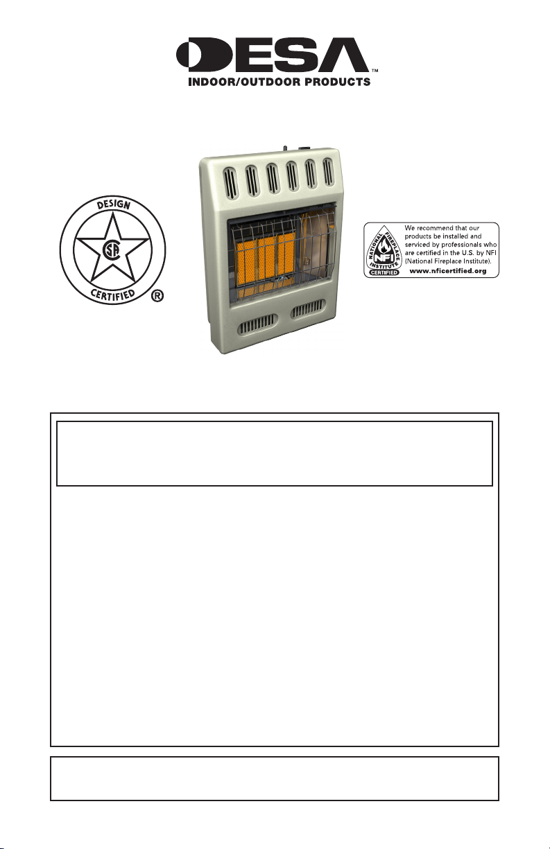
Actual heater may
vary from illustration.
MODELS
NZ100, NZ101, NZ102, NZ103
NZ104, NZ105, NZ106, NZ107
NZ116, NZ117, NZ118, NZ119
WARNING: If the information in this manual is not fol-
lowed exactly, a re or explosion may result causing
property damage, personal injury or loss of life.
— Do not store or use gasoline or other ammable
vapors and liquids in the vicinity of this or any other
appliance.
— WHAT TO DO IF YOU SMELL GAS
• Do not try to light any appliance.
• Do not touch any electrical switch; do not use any
phone in your building.
• Immediately call your gas supplier from a neighbor’s
phone. Follow the gas supplier’s instructions.
• If you cannot reach your gas supplier, call the re
department.
— Installation and service must be performed by a quali-
ed installer, service agency or the gas supplier.
INSTALLER: Leave this manual with the appliance.
CONSUMER: Retain this manual for future reference.
For more information, visit www.desatech.com
Safety Information ............................................... 2
TABLE OF CONTENTS
Local Codes......................................................... 4
Unpacking............................................................ 4
Product Identication ........................................... 4
Product Features ................................................. 4
Air For Combustion And Ventilation ..................... 5
Installation ........................................................... 7
Operating Heater ............................................... 15
Inspecting Heater .............................................. 20
Cleaning and Maintenance ................................ 21
Service Hints ..................................................... 21
SAFETY INFORMATION
Technical Service............................................... 21
Troubleshooting ................................................. 22
Illustrated Parts Breakdown and Parts List........ 26
Specications .................................................... 29
Wiring Diagrams ................................................ 29
Replacement Parts ............................................ 30
Service Publications .......................................... 30
Accessories ....................................................... 30
Parts Central...................................................... 31
Warranty Information ...........................Back Cover
WARNING: Improper installation, adjustment, al-
teration, service or mainte-
nance can cause injury or
property damage. Refer to
this manual for correct in-
stallation and operational
procedures. For assis-
tance or additional infor-
mation consult a qualied
installer, service agency or
the gas supplier.
WARNING: This is an
unvented gas-red heater.
It uses air (oxygen) from the
room in which it is installed.
Provisions for adequate
combustion and ventilation air must be provided.
Refer to Air for Combustion
and Ventilation section on
page 5 of this manual.
This appliance is only for
use with the type of gas
indicated on the rating
plate. This appliance is
not convertible for use
with other gases.
www.desatech.com
This appliance may be installed in an aftermarket,*
per man ent ly lo cat ed,
manufactured (mobile)
home, where not prohibited by local codes.
* Aftermarket: Completion of sale, not for
purpose of resale, from the manufacturer
WARNING: This product con-
tains and/or generates chemicals
known to the State of California
to cause cancer or birth defects
or other reproductive harm.
IMPORTANT: Read this owner’s
manual carefully and completely
before trying to assemble, operate
or service this heater. Improper
use of this heater can cause seri-
ous injury or death from burns, re,
explosion, electrical shock and
carbon monoxide poisoning.
DANGER: Carbon monoxide
poisoning may lead to death!
Carbon Monoxide Poisoning: Early signs of car-
bon monoxide poisoning resemble the u, with
headaches, dizziness or nausea. If you have
these signs, the heater may not be working
properly. Get fresh air at once! Have heater
serviced. Some people are more affected by
carbon monoxide than others. These include
pregnant women, people with heart or lung
disease or anemia, those under the inuence
of alcohol and those at high altitudes.
118621-01B2
SAFETY INFORMATION
Continued
Natural and Propane/LP Gas: Natural and Pro-
pane/LP gases are odorless. An odor-making
agent is added to these gases. The odor
helps you detect a gas leak. However, the
odor added to the gas can fade. Gas may be
present even though no odor exists.
Make certain you read and understand all
warnings. Keep this manual for reference. It
is your guide to safe and proper operation of
this heater.
WARNING: Any change to
this heater or its controls can
be dangerous.
WARNING: Do not use a
blower insert, heat exchanger
insert or other accessory not approved for use with this heater.
Due to high temperatures, the
appliance should be located out
of trafc and away from furniture
and draperies.
Do not place clothing or other
ammable material on or near
the appliance. Never place any
objects on the heater.
Surface of heater becomes very
hot when running heater. Keep
children and adults away from
hot surface to avoid burns or
clothing ignition. Heater will
remain hot for a time after shut-
down. Allow surface to cool
before touching.
Carefully supervise young chil-
dren when they are in the same
room with heater.
Make sure grill guard is in place
before running heater.
Keep the appliance area clear
and free from combustible materials, gasoline and other ammable vapors and liquids.
1. This appliance is only for use with the type
of gas indicated on the rating plate. This
appliance is not convertible for use with
other gases.
2. Do not place propane/LP supply tank(s)
inside any structure. Locate propane/LP
supply tank(s) outdoors.
3. This heater shall not be installed in a
bedroom or bathroom.
4. If you smell gas
• Shut off gas supply
• Do not try to light any appliance
• Do not touch any electrical switch; do
not use any phone in your building
• Immediately call your gas supplier from
a neighbor ’s phone. Follow the gas
supplier’s instructions
• If you cannot reach your gas supplier,
call the re department
5. Always run heater with plaque control
knob at the locked positions. Never set
control knob between locked positions.
Poor combustion and higher levels of
carbon monoxide may result.
6. This heater needs fresh, outside air ventilation to run properly. This heater has an
Oxygen Depletion Sensing (ODS) safety
shutoff system. The ODS shuts down the
heater if not enough fresh air is available.
See Air for Combustion and Ventilation,
page 5.
7. Keep all air openings in front and bottom
of heater clear and free of debris. This will
insure enough air for proper combustion.
8. If heater shuts off, do not relight until you
provide fresh, outside air. If heater keeps
shutting off, have it serviced.
9. Do not run heater
• where ammable liquids or vapors are
used or stored
• under dusty conditions
10. Do not use heater if any part has been
under water. Immediately call a qualied
service technician to inspect the room
heater and to replace any part of the
control system and any gas control which
has been under water.
www.desatech.com
3118621-01B
SAFETY INFORMATION
OF
F
SE
T
P
M
R
O
OM
Continued
11. Turn off and unplug heater and let cool
before servicing. Only a qualied service
person should service and repair heater.
12. Operating heater above elevations of
4,500 feet (1,371 m) could cause pilot
outage.
13. To prevent performance problems, do not
use propane/LP fuel tank of less than 100 lbs.
(45 kg) capacity.
14. Before using furniture polish, wax, carpet
cleaner or similar products, turn heater off. If
heated, the vapors from these products may
create a white powder residue within burner
box or on adjacent walls or furniture.
15. Provide adequate clearances around air
openings.
LOCAL CODES
Install and use heater with care. Follow all local
codes. In the absence of local codes, use the lat-
est edition of The National Fuel Gas Code, ANSI
Z223.1/NFPA 54*.
*Available from:
American National Standards Institute, Inc.
1430 Broadway
New York, NY 10018
National Fire Protection Association, Inc.
Batterymarch Park
Quincy, MA 02269
State of Massachusetts: The installation
must be made by a licensed plumber or
gas tter in the Commonwealth of Massachusetts.
Sellers of unvented propane or natural
gas-red supplemental room heaters shall
provide to each purchaser a copy of 527
CMR 30 upon sale of the unit.
Vent-free gas products are prohibited for
bedroom and bathroom installation in the
Commonwealth of Massachusetts.
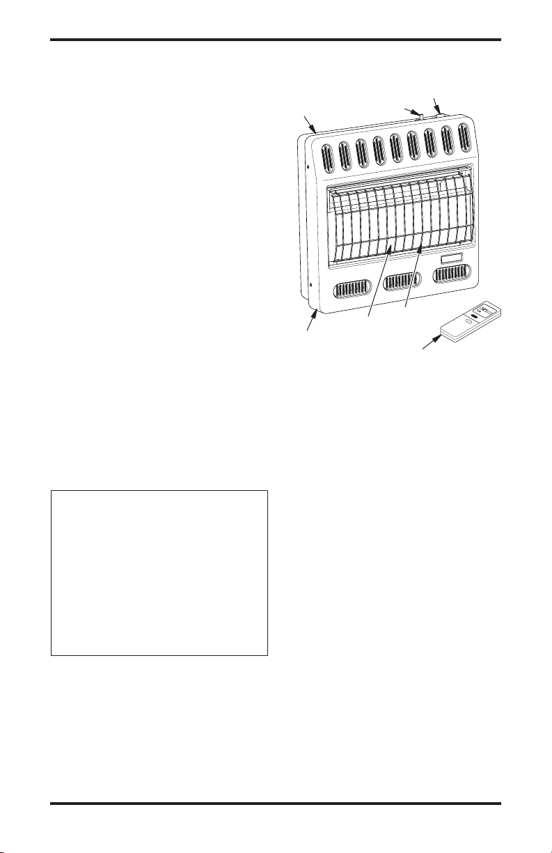
PRODUCT
IDENTIFICATION
Heater
Cabinet
Ignitor Button
Plaque
Front Panel
Figure 1 - Vent-Free Gas Heater
Control Knob
Grill
Guard
Remote Control
PRODUCT FEATURES
SAFETY DEVICE
This heater has a pilot with an Oxygen Depletion Sensing (ODS) safety shutoff system. The
ODS/pilot is a required feature for vent-free
room heaters. The ODS/pilot shuts off the
heater if there is not enough fresh air.
PIEZO IGNITION SYSTEM
This heater has a piezo ignitor. This system requires no matches, batteries or other sources
to light heater.
THERMOSTATIC HEAT CONTROL
This heater is operated thermostatically by
the remote control. This results in the greatest heater comfort. This can also result in
lower gas bills.
UNPACKING
1. Remove heater from carton.
2. Remove all protective packaging applied
to heater for shipment.
3. Check heater for any shipping damage.
If heater is damaged, promptly return to
where you bought heater.
www.desatech.com
118621-01B4
AIR FOR COMBUSTION
AND VENTILATION
WARNING: This heater shall
not be installed in a conned
space or unusually tight construction unless provisions are
provided for adequate combustion and ventilation air. Read the
following instructions to insure
proper fresh air for this and
other fuel-burning appliances
in your home.
Today’s homes are built more energy efcient
than ever. New materials, increased insulation
and new construction methods help reduce
heat loss in homes. Home owners weather
strip and caulk around windows and doors
to keep the cold air out and the warm air in.
During heating months, home owners want
their homes as airtight as possible.
While it is good to make your home energy
efcient, your home needs to breathe. Fresh
air must enter your home. All fuel-burning appliances need fresh air for proper combustion
and ventilation.
Exhaust fans, replaces, clothes dryers and
fuel burning appliances draw air from the
house to operate. You must provide adequate
fresh air for these appliances. This will insure proper venting of vented fuel-burning
appliances.
PROVIDING ADEQUATE
VENTILATION
The following are excerpts from National Fuel
Gas Code, ANSI Z223.1/NFPA 54, Section
5.3, Air for Combustion and Ventilation.
All spaces in homes fall into one of the three
following ventilation classications:
1. Unusually Tight Construction
2. Unconned Space
3. Conned Space
The information on pages 5 through 7 will help
you classify your space and provide adequate
ventilation.
Unusually Tight Construction
The air that leaks around doors and windows
may provide enough fresh air for combustion
and ventilation. However, in buildings of unusually tight construction, you must provide
additional fresh air.
Unusually tight construction is dened as
construction where:
a. walls and ceilings exposed to the outside
atmosphere have a continuous water
vapor retarder with a rating of one perm
-11
(6x10
kg per pa-sec-m2) or less with
openings gasketed or sealed and
b. weather stripping has been added on
openable windows and doors and
c. caulking or sealants are applied to areas
such as joints around window and door
frames, between sole plates and oors,
between wall-ceiling joints, between wall
panels, at penetrations for plumbing, electrical and gas lines and at other openings.
If your home meets all of the three criteria
above, you must provide additional fresh air.
See Ventilation Air From Outdoors, page 7.
If your home does not meet all of the three
criteria above, proceed to Determining Fresh-
Air Flow For Heater Location, page 6.
Conned and Unconned Space
The National Fuel Gas Code, ANSI Z223.1/
NFPA 54 denes a conned space as a space
whose volume is less than 50 cubic feet per
1,000 Btu per hour (4.8 m3 per kw) of the aggregate input rating of all appliances installed
in that space and an unconned space as a
space whose volume is not less than 50 cubic
feet per 1,000 Btu per hour (4.8 m3 per kw)
of the aggregate input rating of all appliances
installed in that space. Rooms communicating
directly with the space in which the appliances
are installed*, through openings not furnished
with doors, are considered a part of the unconned space.
* Adjoining rooms are communicating only if
there are doorless passageways or ventilation
grills between them.
www.desatech.com
5118621-01B
AIR FOR COMBUSTION
AND VENTILATION
Continued
DETERMINING FRESH-AIR FLOW
FOR HEATER LOCATION
Determining if You Have a Conned or
Unconned Space
Use this work sheet to determine if you have a
conned or unconned space.
Space: Includes the room in which you will install
heater plus any adjoining rooms with doorless
passageways or ventilation grills between the
rooms.
1. Determine the volume of the space (length
x width x height).
Length x Width x Height =__________cu. ft.
(volume of space)
Example: Space size 20 ft. (length) x 16 ft.
(width) x 8 ft. (ceiling height) = 2560 cu. ft.
(volume of space)
If additional ventilation to adjoining room
is supplied with grills or openings, add the
volume of these rooms to the total volume
of the space.
2. Multiply the space volume by 20 to determine
the maximum Btu/Hr the space can support.
______ (volume of space) x 20 = (Maximum
Btu/Hr the space can support)
Example: 2560 cu. ft. (volume of space) x 20 =
51,200 (maximum Btu/Hr the space can support)
3. Add the Btu/Hr of all fuel burning appliances
in the space.
Vent-free heater ____________ Btu/Hr
Gas water heater* ____________ Btu/Hr
Gas furnace ____________ Btu/Hr
Vented gas heater ____________ Btu/Hr
Gas replace logs ____________ Btu/Hr
Other gas appliances*
Total = ___________ Btu/Hr
* Do not include direct-vent gas appliances.
Direct-vent draws combustion air from the
outdoors and vents to the outdoors.
Example:
Gas water heater ____________ Btu/Hr
Vent-free heater + ___________ Btu/Hr
Total = ___________ Btu/Hr
+ ___________ Btu/Hr
40,000
20,000
60,000
4. Compare the maximum Btu/Hr the space
can support with the actual amount of Btu/Hr
used.
_______ Btu/Hr (maximum can support)
_______ Btu/Hr (actual amount used)
Example:
51,200 Btu/Hr (maximum can support)
60,000 Btu/Hr (actual amount used)
The space in the above example is a conned
space because the actual Btu/Hr used is more
than the maximum Btu/Hr the space can support. You must provide additional fresh air. Your
options are as follows:
A. Rework worksheet, adding the space of an
adjoining room. If the extra space provides
an unconned space, remove door to adjoining room or add ventilation grills between
rooms. See Ventilation Air From Inside
Building, page 7.
B. Vent room directly to the outdoors. See
Ventilation Air From Outdoors, page 7.
C. Install a lower Btu/Hr heater, if lower Btu/Hr
size makes room unconned.
If the actual Btu/Hr used is less than the maximum Btu/Hr the space can support, the space is
an unconned space. You will need no additional
fresh air ventilation.
WARNING: If the area in
which the heater may be operated is smaller than that dened
as an unconned space or if the
building is of unusually tight
construction, provide adequate
combustion and ventilation air
by one of the methods described
in the National Fuel Gas Code,
ANSI Z223.1/NFPA 54 Section 5.3
or applicable local codes.
www.desatech.com
118621-01B6
AIR FOR COMBUSTION
Or
Remove
Door into
Adjoining
Room,
Option 3
Ventilation Grills
Into Adjoining Room,
Option 2
12"
12"
Ventilation
Grills into
Adjoining
Room,
Option 1
Outlet
Air
Ventilated
Attic
Outlet
A
ir
Inlet
Air
Inlet Air
Ventilated
Crawl Space
To
Crawl
Space
To Attic
AND VENTILATION
Continued
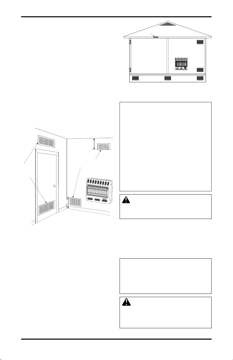
VENTILATION AIR
Ventilation Air From Inside Building
This fresh air would come from an adjoining
unconned space. When ventilating to an
adjoining unconned space, you must provide
two permanent openings: one within 12" of the
ceiling and one within 12" of the oor on the
wall connecting the two spaces (see options
1 and 2, Figure 2). You can also remove door
into adjoining room (see option 3, Figure 2).
Follow the National Fuel Gas Code, ANSI
Z223.1/NFPA 54, Section 5.3, Air for Combustion and Ventilation for required size of
ventilation grills or ducts.
Figure 3 - Ventilation Air from Outdoors
INSTALLATION
NOTICE: This heater is intended
for use as supplemental heat.
Use this heater along with your
primary heating system. Do not
install this heater as your primary heat source. If you have a
central heating system, you may
run system’s circulating blower
while using heater. This will help
circulate the heat throughout the
house. In the event of a power
outage, you can use this heater
as your primary heat source.
Figure 2 - Ventilation Air from Inside
Building
Ventilation Air From Outdoors
Provide extra fresh air by using ventilation
grills or ducts. You must provide two permanent openings: one within 12" of the ceiling
and one within 12" of the oor. Connect these
items directly to the outdoors or spaces open
to the outdoors. These spaces include attics
and crawl spaces. Follow the National Fuel
Gas Code, ANSI Z223.1/NFPA 54, Section
5.3, Air for Combustion and Ventilation for
required size of ventilation grills or ducts.
IMPORTANT: Do not provide openings for
inlet or outlet air into attic if attic has a thermostat-controlled power vent. Heated air entering
the attic will activate the power vent.
www.desatech.com
WARNING: A qualied service person must install heater.
Follow all local codes.
CHECK GAS TYPE
Use only the correct type of gas (natural or
propane/LP). If your gas supply is not the
correct gas type, do not install heater. Call
dealer where you bought heater for proper
type heater.
This appliance is only for use
with the type of gas indicated on
the rating plate. This appliance
is not convertible for use with
other gases.
WARNING: This appliance
is equipped for natural or propane/LP gas. Field conversion
is not permitted.
7118621-01B
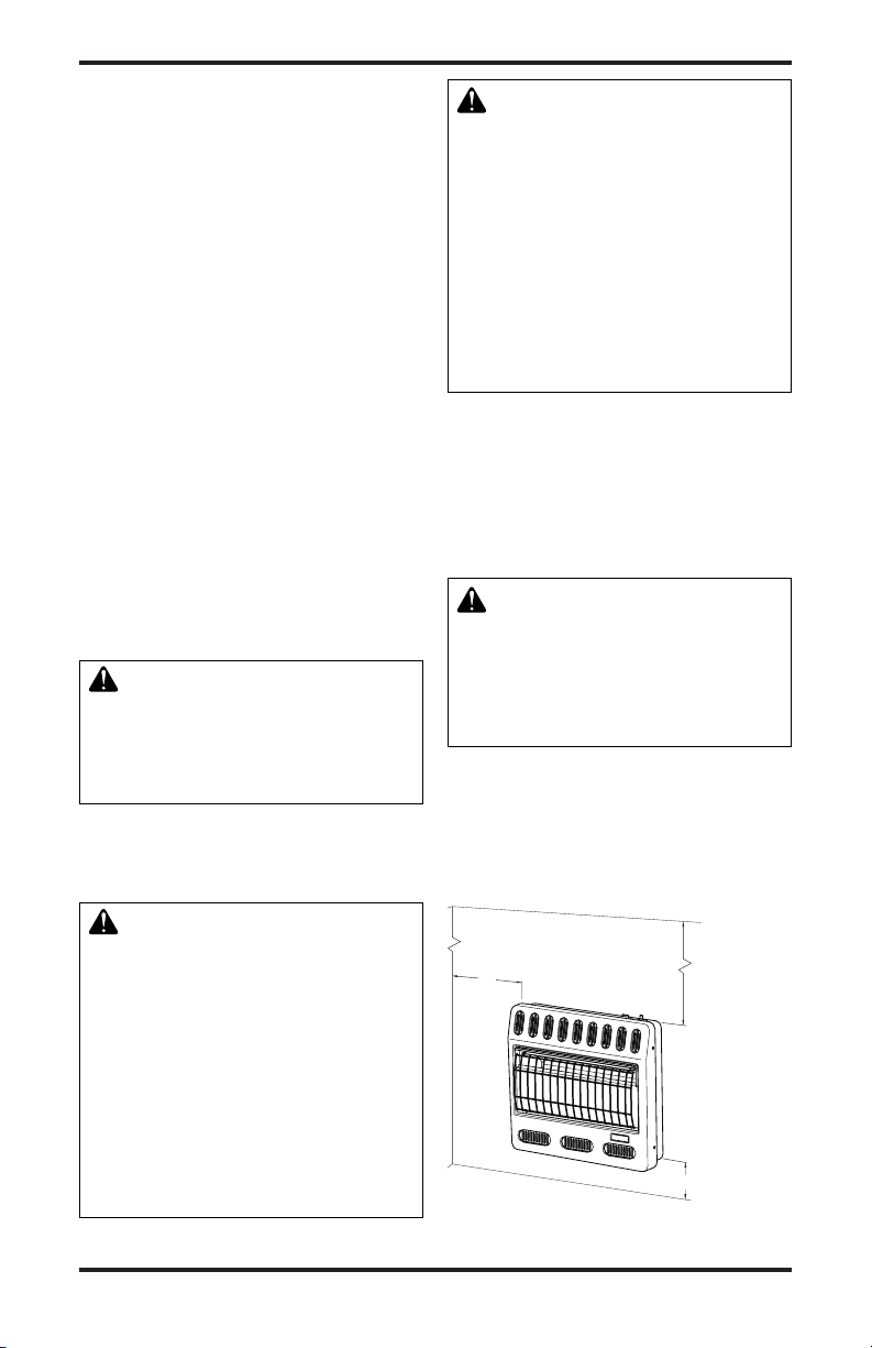
INSTALLATION
Minimum
From
Sides Of
Heater
2" (5.1 cm)
FLOOR
CEILING
36"
(91.5 cm)
Minimum
Minimum To
Top Surface
Of Carpeting,
Tile Or Other
Combustible
Material
Left
Side
Right
Side
10" (25.4 cm)
Continued
INSTALLATION ITEMS
Before installing heater, make sure you have
the items listed below.
• for propane/LP gas, external regulator
(supplied by installer)
• piping (check local codes)
• sealant (resistant to propane/LP gas)
• equipment shutoff valve *
• ground joint union
• sediment trap
• tee joint
• pipe wrench
• for natural gas, test gauge connection*
* A CSA design-certied equipment shutoff
valve with 1/8" NPT tap is an acceptable alternative to test gauge connection. The optional
CSA design-certied equipment shutoff valve
can be purchased from your dealer. See Ac-
cessories, page 30.
LOCATING HEATER
This heater is designed to be mounted on
a wall.
WARNING: Maintain the
minimum clearances shown
in Figure 4. If you can, provide
greater clearances from oor,
ceiling and joining wall.
You can locate heater on oor, away from a
wall. An optional oor mounting stand is needed. Purchase the oor mounting stand from
your dealer. See Accessories, page 30.
CAUTION: This heater cre-
ates warm air currents. These
currents move heat to wall sur-
faces next to heater. Installing
heater next to vinyl or cloth wall
coverings or operating heater
where impurities (such as, but
not limited to, tobacco smoke,
aromatic candles, cleaning uids, oil or kerosene lamps, etc.) in
the air exist, may discolor walls
or cause odors.
IMPORTANT: Vent-free heaters add moisture
to the air. Although this is benecial, installing
heater in rooms without enough ventilation
air may cause mildew to form from too much
moisture. See Air for Combustion and Ventila-
tion, page 5. If high humidity is experienced,
a dehumidier may be used to help lower the
water vapor content in the air.
CAUTION: If you install the
heater in a home garage
•
heater pilot and burner must be at
least 18" (45.7 cm) above oor
• locate heater where moving
vehicle will not hit it
For convenience and efciency, install heater
• where there is easy access for operation,
inspection and service
• in coldest part of room
To use fan, locate heater near an electrical
outlet.
WARNING: Never install the
heater
• in a bedroom or bathroom
• in a recreational vehicle
• where curtains, furniture,
clothing or other ammable
objects are less than 36"
(91.5 cm) from the front, top
or sides of the heater
• as a replace insert
• in high trafc areas
• in windy or drafty areas
www.desatech.com
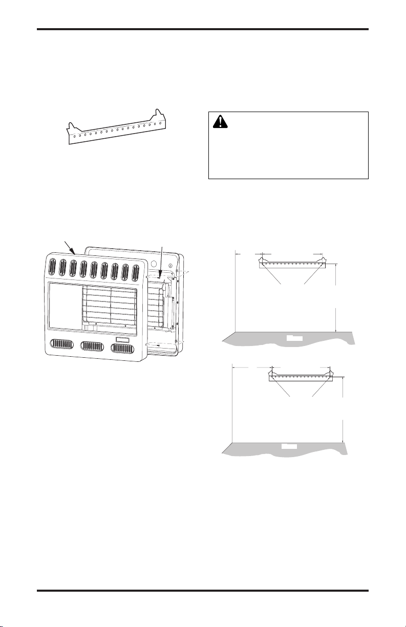
Figure 4 - Mounting Clearances As
Viewed From Front of Heater
118621-01B8
INSTALLATION
14" (35.6 cm)
18 3/4"
(47.6 cm)
Min.
12"
(30.4
cm)
Min.
Ad j oi nin g W all
Only Insert Mounting
Screws Through Last
Hole On Each End
Floor
18 3/4"
(47.6 cm)
Min.
16"
(40.6 cm)
Min.
14" (35.6 cm)
18 3/4"
(47.6 cm)
Min.
12"
(30.4
cm)
Min.
Ad joi ni ng Wa ll
14" (35.6 cm)
Ad joi ni ng Wa ll
Only Insert Mounting
Screws Through Last
Hole On Each End
Only Insert Mounting
Screws Through Last
Hole On Each End
Floor
Floor
Continued
INSTALLING HEATER TO WALL
Mounting Bracket
Locate mounting bracket in heater carton. Remove mounting bracket from heater carton.
Figure 5 - Mounting Bracket
Removing Front Panel Of Heater
1. Remove the four painted screws, two on
each side of front panel.
2.
Pull bottom of front panel forward, then out.
3. Remove any remaining packaging materials.
Front Panel
Screw
Decide which method better suits your needs.
Either method will provide a secure hold for
the mounting bracket.
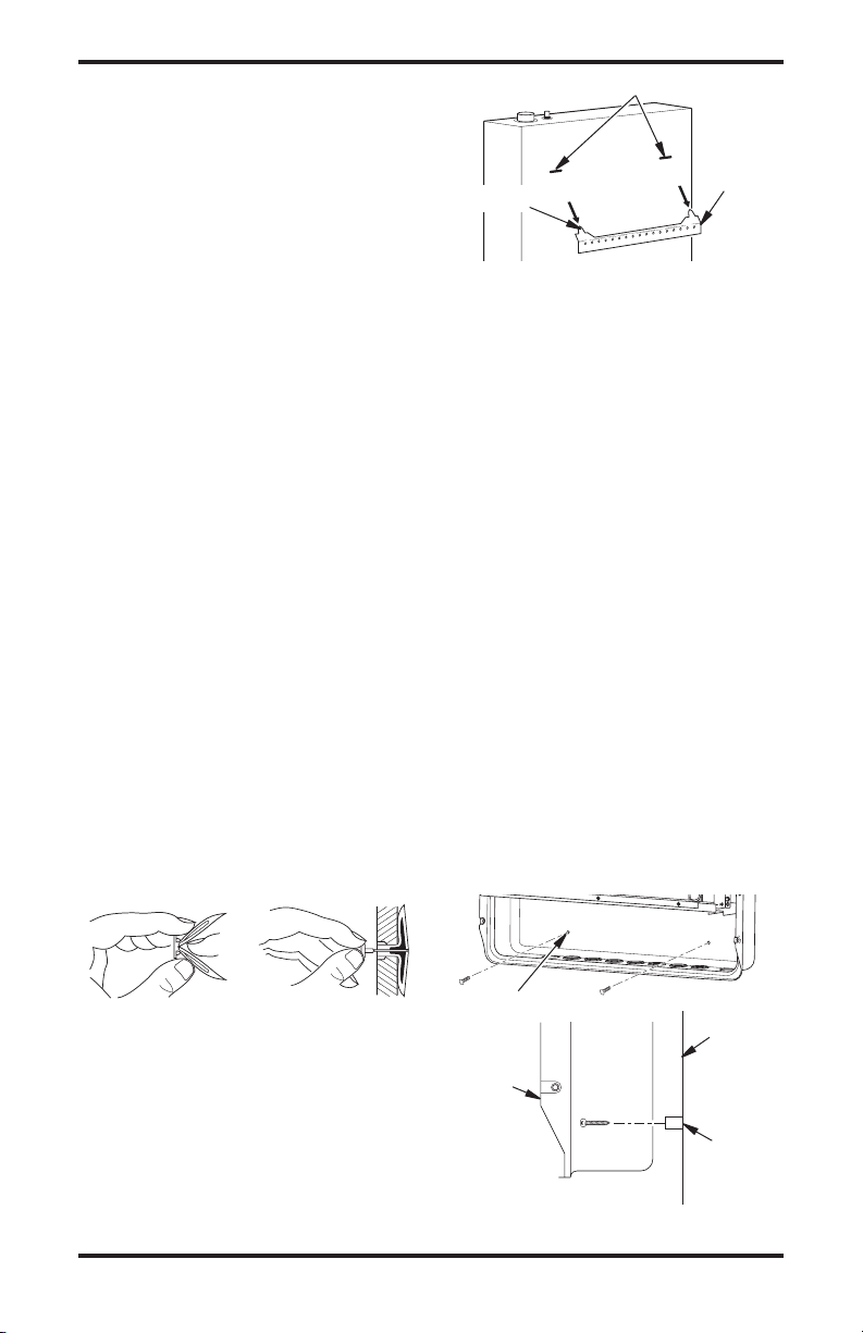
Marking Screw Locations
1. Tape mounting bracket to wall where
heater will be located. Make sure mounting bracket is level.
WARNING: Maintain mini-
mum clearances shown in Figure
7. If you can, provide greater
clearances from oor and joining wall.
2.
Mark screw locations on wall (see Figure 7).
Note: Only mark last hole on each end of
mounting bracket. Insert mounting screws
through these holes only.
3. Remove tape and mounting bracket from
wall.
Figure 6 - Removing Front Panel Of
Heater
Methods For Attaching Mounting Bracket
To Wall
Only use last hole on each end of mounting
bracket to attach bracket to wall. These two
holes are 14" (35.6 cm) apart from their centers. Attach mounting bracket to wall in one
of two ways:
1. Attaching to wall stud
2. Attaching to wall anchor
Attaching to Wall Stud: This method provides
the strongest hold. Insert mounting screws
through mounting brack et and into wall
studs.
Attaching to Wall Anchor: This method allows
you to attach mounting bracket to hollow walls
(wall areas between studs) or to solid walls
(concrete or masonry).
www.desatech.com
3 Plaque Heater
5 Plaque Heater
Figure 7 - Mounting Bracket Clearances
Attaching Mounting Bracket To Wall
Note: Wall anchors, mounting screws and
spacers are in hardware package. The hardware package is provided with heater.
9118621-01B
INSTALLATION
Side View
Front View
Continued
Attaching To Wall Stud Method
For attaching mounting bracket to wall studs
1. Drill holes at marked locations using 9/64"
drill bit.
2. Place mounting bracket onto wall. Line
up last hole on each end of bracket with
holes drilled in wall.
3. Insert mounting screws through bracket
and into wall studs.
4. Tighten screws until mounting bracket is
rmly fastened to wall studs.
Attaching To Wall Anchor Method
For attaching mounting bracket to hollow
walls (wall areas between studs) or solid walls
(concrete or masonry)
1. Drill holes at marked locations using
5/16" drill bit. For solid walls (concrete or
masonry), drill at least 1" (2.5 cm) deep.
2. Fold wall anchor as shown in Figure 8.
3. Insert wall anchor (wings rst) into hole.
Tap anchor ush to wall.
4. For thin walls [1/2" (1.3 cm) or less], insert
red key into wall anchor. Push red key to
“pop” open anchor wings (see Figure 9).
IMPORTANT: Do not hammer key! For
thick walls [over 1/2" (1.3 cm) thick] or
solid walls, do not pop open wings.
5. Place mounting bracket onto wall. Line up
last hole on each end of bracket with wall
anchors.
6. Insert mounting screws through bracket
and into wall anchors.
7. Tighten screws until mounting bracket is
rmly fastened to wall.
Horizontal Slots
Mounting
Bracket
(attached
Stand-Out Tab
to wall)
Figure 10 - Mounting Heater Onto
Mounting Bracket
Installing Bottom Mounting Screws
1. Locate two bottom mounting holes. These
holes are near bottom on back panel of
heater (see Figure 11).
2. Mark screw locations on wall.
3. Remove heater from mounting bracket.
4. If installing bottom mounting screws into
hollow or solid wall, install wall anchors.
Follow steps 1 through 4 under Attaching
To Wall Anchor Method.
If installing bottom mounting screw into
wall stud, drill holes at marked locations
using 9/64" drill bit.
5. Replace heater onto mounting bracket.
6. Place spacers between bottom mounting
holes and wall anchor or drilled hole.
7.
Hold spacer in place with one hand. With other
hand, insert mounting screw through bottom
mounting hole and spacer. Place tip of screw
in opening of wall anchor or drilled hole.
8. Tighten both screws until heater is rmly
secured to wall. Do not over tighten.
Note: Do not replace front panel at this
time. Replace front panel after making
gas connections and checking for leaks
(see page 12).
Figure 8 - Folding
Anchor
Figure 9 - Popping
Open Anchor Wings
For Thin Walls
Placing Heater On Mounting Bracket
1. Locate two horizontal slots on back panel
of heater.
2. Place heater onto mounting bracket. Slide
horizontal slots onto stand-out tabs on
mounting bracket.
www.desatech.com
Bottom
Mounting
Holes
Wall
Heater
Spacer
Figure 11 - Installing Bottom Mounting
Screws
118621-01B10
 Loading...