


Propane/LP Patio Heater
Owner’s Manual
86NH
WARNING: For
outdoor use only.
MODELS SPC-54PHW, SPC-54PHB, SPC-54PHT AND SPC-54PHS
IMPORTANT: Read and understand this manual before
assembling, starting or servicing heater. Improper use
of heater can cause serious injury. Keep this manual for
future reference.
FOR YOUR SAFETY
Do not store or use gasoline or other flammable vapors
and liquids in the vicinity of this or any other appliance.
FOR YOUR SAFETY
If you smell gas:
1. Shut off gas to the appliance.
2. Extinguish any open flame.
3. If odor continues, immediately call your gas
supplier.
Save this manual for future reference.
For more information, visit www.desatech.com

WARNING: Improper installation, adjustment, alteration, service or maintenance can cause injury, property
damage, or death. Read the installation, operating, and
maintenance instructions thoroughly before installing
or servicing this equipment.
Specifications ...................................................... 2
Safety Information ............................................... 2
Propane/LP Safety ..............................................
Assembly Instructions ......................................... 4
Operating Instructions ......................................... 7
Storage ................................................................ 8
Servicing .............................................................. 9
Replacement Parts .............................................. 9
4
Technical Service ................................................
Illustrated Parts Breakdown and Parts List ....... 10
Warranty and Repair Service ............................ 12
SPECIFICATIONS
TABLE OF CONTENTS
Rating 40,000 Btu/hr (11.7 kW)
Type of Gas Propane/LP Only
Gas Supply Pressure to regulator Maximum - 150 psi (1034.2 kPa) Minimum - 5 psi (34.5 kPa)
Gas Supply Pressure Regulator out 11" W.C. (2.74 kPa)
Ignition Piezo Ignition
Fuel Consumption 1.86 lbs./hr (.84 kg/hr)
Flame Safety Thermocouple Operated Gas Valve
SAFETY INFORMATION
WARNING: This product con-
tains and/or generates chemicals
known to the State of California
to cause cancer or birth defects,
or other reproductive harm.
WARNING: Not for home or
recreational vehicle use.
WARNING: Fire, burn, inha-
lation, and explosion hazard.
Keep solid combustibles, such
as building materials, paper or
cardboard, a safe distance away
from the heater as recommended
by the instructions. Never use
the heater in spaces which do or
may contain volatile or airborne
combustibles, or products such
as gasoline, solvents, paint thin
ner, dust particles or unknown
chemicals.
We cannot foresee every use which may be made
of our heaters. Check with your local fire safety
authority if you have questions about heater use.
Other standards govern the use of fuel gases and
heat producing products for specific uses. Your
local authorities can advise you about these.
Carbon Monoxide Poisoning: Direct-Fired means
that all of the combustion products enter the heated
space. Even though this heater operates very close
to 100 percent combustion efficiency, it still produces small amounts of carbon monoxide. Some
people are more affected by carbon monoxide than
others. Early signs of carbon monoxide poisoning
resemble the flu, with headaches, dizziness, and/or
nausea. If you have these signs, the heater may not
be working properly. Get fresh air at once! Check
for proper ventilation and have heater serviced.
Propane Gas: Propane gas is odorless. An odor-
making agent is added to propane gas. The odor
helps you detect a propane gas leak. However, the
odor added to propane gas can fade. Propane gas
may be present even though no odor exists.
-
9
2
www.desatech.com
114144-01E

SAFETY INFORMATION
Continued
This is a propane, direct-fired heater. Propane is
heavier than air. If propane leaks from a connection
or fitting, it sinks to the floor, collecting there with
the surrounding air, forming a potentially explosive
mixture. Obviously, propane leaks should be avoided,
so set up the propane supply with utmost care. Read
Propane/LP Safety, page 4 for additional informa
tion about detecting propane leaks. Leak check new
connections or reconnections with a soap and water
solution and follow all connection instructions herein.
Also, ask your propane dealer for advice on the
propane application and supply installation and ask
them to check it if there are any questions.
When the heater is to be operated in the presence of
other people the user is responsible for properly ac
quainting those present with the safety precautions
and instructions, and of the hazards involved.
Make certain you read and understand all warn
ings. Keep this manual for reference. It is your
guide to safe and proper operation of this heater.
1. Check the heater thoroughly for damage. DO
NOT operate a damaged heater.
2. DO NOT modify the heater or operate a heater
which has been modified from its original
condition.
3. Use only propane/LP gas.
4. Use only VAPOR WITHDRAWAL propane
supply. The propane cylinder must be arranged
for vapor-withdrawal, in accordance with the
Compress Gas Associations, Small Propane
Bottle Assembly. If there is any question about
vapor withdrawal, ask your propane dealer.
5. Never use the heater if the ballast weight is
not assembled onto the base. The base must
be weighted to avoid tipping.
6. Use only the hose and regulator assembly
provided with the heater.
7. Inspect hose assembly before each use of the
heater. If there is excessive abrasion or wear,
or hose is cut, replace with hose assembly
listed on parts list before using heater.
8. This heater is for OUTDOOR USE ONLY,
even so, make sure that there is ample fresh air
ventilation. Do not use in buildings, garages
or other enclosed spaces.
9. If at any time gas odor is detected, IMMEDI
ATELY DISCONTINUE operation until the
source of gas has been located and corrected.
Read Propane/LP Safety, page 4 for additional
information about detecting propane leaks.
10. Install the heater such that it is not directly
exposed to water spray, rain and/or dripping
water.
11. Maintain minimum clearance to people or
normal combustible material (like paper) of
3.6 ft. (1100 mm) from top and 2 ft. (609 mm)
from the reflector.
12. Operate only on a stable, level surface.
13. Do not spray aerosols near the heater during
use or shortly thereafter.
14. Do not clean heater with combustible or cor
rosive cleaners. Use warm, soapy water.
15. Check control compartment burners and cir
culation air passageways for free air passage,
make sure that there are no obstructions. These
areas are a common location for spider webs,
which can present a dangerous condition,
damage the heater and render it unsafe for
use. The heater must be checked if any of the
following conditions exist:
a) Gas smell along with predominate yellow
tipping of the burner.
b) Heater does not reach temperature.
c) Uneven burner glow.
d) Burner makes popping noises during nor
mal use, other than during shutdown.
16. Use only soapy water (1 part liquid dishwash
ing detergent to 3 parts water) to conduct
leak tests whenever a propane cylinder is
connected. Bubbles indicate a leak.
17. Do not adjust gas regulator. If you are unsure
of your appliances gas type or pressure, call
a qualified service person.
18. Place the control knob on "OFF" position
when heater is not in use.
19. Always disconnect the gas supply after the
heater is turned "OFF".
20. Do not move, handle or service while hot or
burning.
21. Allow 45 minutes to cool down after use
before attempting to move heater.
22. Do not operate this appliance in windy con
ditions. Maximum allowable wind speed is
10 mph (16 Km/h).
23. Do not operate this appliance in temperature
conditions below 40° F (5° C).
24. Keep heater away from areas where flammable
liquids, vapors or solids are stored or used.
-
25. If operated in salt air environments, the
unit will require more frequent cleaning;
otherwise, the longevity of the unit will
deteriorate rapidly. Use warm soapy water to
clean the unit.
-
-
-
-
-
114144-01E
www.desatech.com
3

SAFETY INFORMATION
Continued
26. Items or material, when stored under the
heater, will be subjected to radiant heat and
could be seriously damaged.
27. Use only in accordance with local codes, or in
the absence of local codes, with the National
Fuel Gas Code ANSI Z223.1
Any guard or other protective device
removed for servicing must be re
placed prior to operating the heater.
Surface temperatures become very
hot when operating heater. Children
and adults should stay away to avoid
burns or clothing ignition.
Young children should be carefully
supervised when they are in the area
of the heater.
Clothing or other flammable mate
rials should not be hung from the
heater, or placed on or near heater.
.
-
-
PROPANE/LP SAFETY
WARNING: For outdoor use
only.
ASPHYXIATION HAZARD
• Do not use this heater for heating human
living quarters.
• Do not use in unventilated areas.
• The flow of combustion and ventilation
air must not be obstructed.
• Proper ventilation air must be provided
to support the combustion air require
ments of the heater being used.
• Refer to the Specifications, page 2, heater
data plate or contact DESA Heating Prod
ucts to determine combustion air ventilation requirements of the heater.
• Lack of proper ventilation air will lead
to improper combustion.
• Improper combustion can lead to carbon
monoxide poisoning leading to serious
injury or death. Symptom of carbon mon
oxide poisoning can include headaches
dizziness and difficulty in breathing.
-
-
-
Installation and repair should be
done by a qualified service person.
The heater should be inspected
before use and at least annually by
a qualified service person. More
frequent cleanings may be required
as necessary. It is imperative that
control compartments, burners and
circulating air passageways of the
heater be kept clean.
CAUTION: The gas pressure
regulator provided with this appliance must be used. This regulator is set for an output pressure
of 11" W.C. (2.74 kPa).
4
www.desatech.com
ASSEMBLY INSTRUCTIONS
Tools Required:
• #2 Phillips Head Screwdriver 1
• Adjustable Wrench 2
Inspect heater components for possible shipping
damage. If any is found, immediately notify the
dealer. Check to make sure that all components are
included with your heater (see pages 10 and 11).
POLE ASSEMBLY
1. Attach legs to base using two bolts, two lock
washers and two nuts (see Figure 1, page 5).
Insert bolts through legs and into top of base.
Attach lock washers and nuts from underneath
base. Finger tighten only. Repeat for each leg.
Do not fully tighten until next step.
2. Secure pole support to legs using two bolts, two
lock washers and two nuts. Repeat for each leg.
Wrench tighten nuts and bolts from step 1 and 2.
3. Attach ballast weight to base using one, long bolt,
lock washer and nut (see Figure 1, page 5).
114144-01E

ASSEMBLY INSTRUCTIONS
Continued
4.
Insert manifold into pole support (see Figure 2).
Insert the manifold assembly through the post by
passing through the hole in the post support. Note:
Make sure hose and regulator assembly attached
to manifold are never bent or kinked during instal
lation and operation of heater.
5. Attach pole to pole support (Figure 3). Place
pole into pole support center connector.
Tighten six set screws with hex allen wrench
supplied with heater. Note: Set screws are
threaded inside post support.
6. Put propane/LP cylinder cover on base assembly
(see Figure 4). Slide propane/LP cylinder cover
over pole and pole support. Be sure that the pro
pane/LP cylinder cover rests level on the base.
Pole
Support
-
Pole
Support
-
Figure 2 - Installing Manifold Assembly
Pole
Manifold
Assembly
Legs
Base
Ballast
Weight
Figure 1 - Base Assembly
Pole
Support
Figure 3 - Pole to Pole Support
Pole
Propane/LP
Cylinder
Cover
Base
Figure 4 - Propane/LP Cylinder Cover
114144-01E
www.desatech.com
5

ASSEMBLY INSTRUCTIONS
Continued
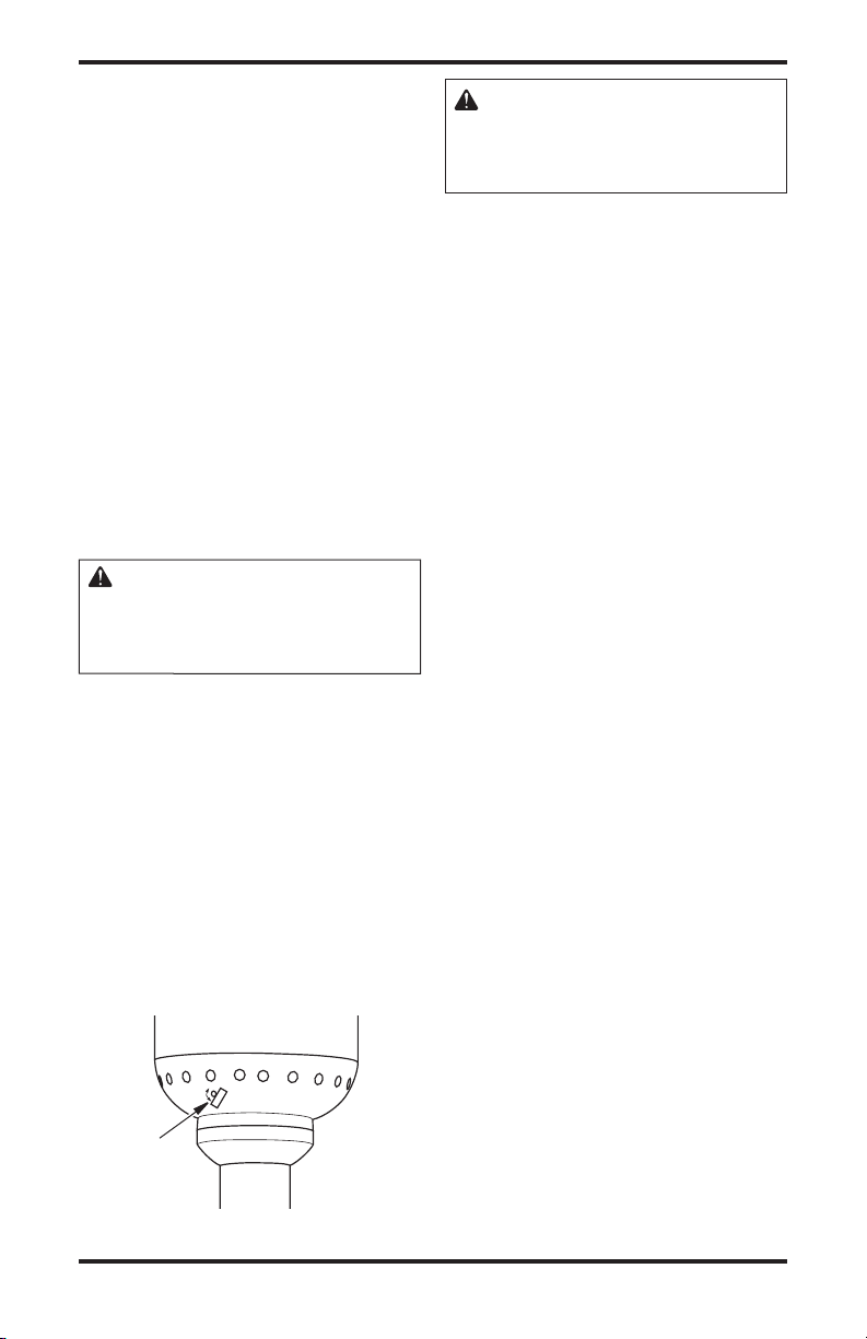
BURNER AND CONTROL
ASSEMBLY
The connection between the fuel line to the burner
is a quick connect connection type. Follow these
steps to assemble, while referring to Figure 5.
1.
Pull manifold out of top end of pole.
2. Slide/move quick connect collar of manifold
to the back.
3. Attach manifold to burner and control assem
bly by pushing burner and control assembly
connection all the way through manifold.
4. Make sure manifold and burner assembly snap
in properly.
5. Release the quick connect collar of manifold
that was slid to the back in step 2.
6. Place burner and control assembly onto pole.
Burner and
Control
Assembly
Manifold
Assembly
CHECK FOR LEAKS
IMPORTANT: The heater must be leak tested before any further assembly is done. Use only a soap
and water solution. DO NOT USE FLAME.
Turn control knob to the OFF position. Securely
connect regulator to propane/LP gas cylinder.
Open propane/LP cylinder valve. Apply a soap
and water solution to connections at the manifold,
burner, and control assembly. Bubbles forming
show a leak. In case of any leaks, turn off pro
pane/LP cylinder valve, remove manifold, check
and clean connection. Reconnect manifold and
leak test again.
Upon completion of leak test, and when there is
no sign of a leak, turn off propane/LP cylinder
valve and disconnect regulator from propane/LP
gas cylinder. Remove propane/LP gas cylinder and
continue to next step.
POLE AND BURNER/CONTROL
ASSEMBLY
Attach pole to burner and control assembly (see
Figure 6). Align the three holes. Insert a small
bolt in each hole and tighten using #2 Phillips
head screwdriver.
-
Pole
Figure 5 - Connecting Manifold Assembly
to Burner and Control Assembly
6
www.desatech.com
Figure 6 - Attach Burner and Control
Assembly to Pole
114144-01E
ASSEMBLY INSTRUCTIONS
Continued
MANIFOLD FIXING PLATE AND
POLE SUPPORT
1. Locate threaded hole underneath post support.
This hole is for mounting manifold fixing plate
(see Figure 7).
2. Align holes on manifold fixing plate with
threaded holes on pole support.
3. Make sure manifold fixing plate is facing
downward see (Figure 7).
4. Use a bolt to tighten manifold fixing plate to
post support using #2 Phillips head screw
driver.
5. Turn manifold fixing plate so it will hold
manifold in place.
6. Tighten bolt so manifold fixing plate will not
move.
Manifold
Fixing Plate
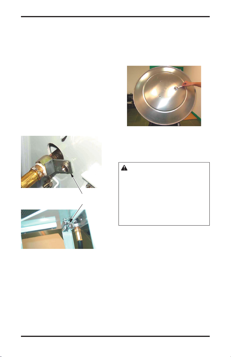
DOME AND EMITTER
Gently lay heater assembly on its side using one of
the shipping styrofoam inserts to prop up the top
half of heater. Align holes in dome with threaded
studs in emitter cover. Secure dome to emitter
using three cap nuts. Tighten with an adjustable
wrench. Stand heater back to upright position.
-
Figure 8 - Attaching Dome to Emitter
OPERATING
INSTRUCTIONS
WARNING: If you smell gas:
• Shut off gas to the appliance.
• Extinguish any open flames.
• If odor continues, immediately
call your gas supplier.
See safety warnings and pre
cautions starting on the front
page of this manual for more
information.
-
Figure 7 - Attaching Manifold Fixing
Plate to Post Support
114144-01E
PREPARING FOR OPERATION
1. Check heater for possible shipping damage. If
any is found, immediately notify the factory.
2. Follow all safety information.
3. Check and assure control knob is in the OFF
position.
4. Place propane/LP gas cylinder inside cylinder
base. Securely connect regulator to propane/LP
gas cylinder.
5. Turn cylinder valve on. Apply a soap and
water solution to connection at regulator and
cylinder. Bubbles forming show a leak.
6. In case of any leaks, turn off propane/LP cyl
inder valve, undo leaking connection. Check
and clean connection. Reconnect regulator and
leak test again.
www.desatech.com
-
7
OPERATING INSTRUCTIONS
Continued
START
1. Purge gas line leading to pilot assembly. Press
and turn control knob to HIGH position, keep
ing it pressed in for 1 to 2 minutes. Note: When
a new or refilled gas cylinder is installed, heater
will need to be purged again.
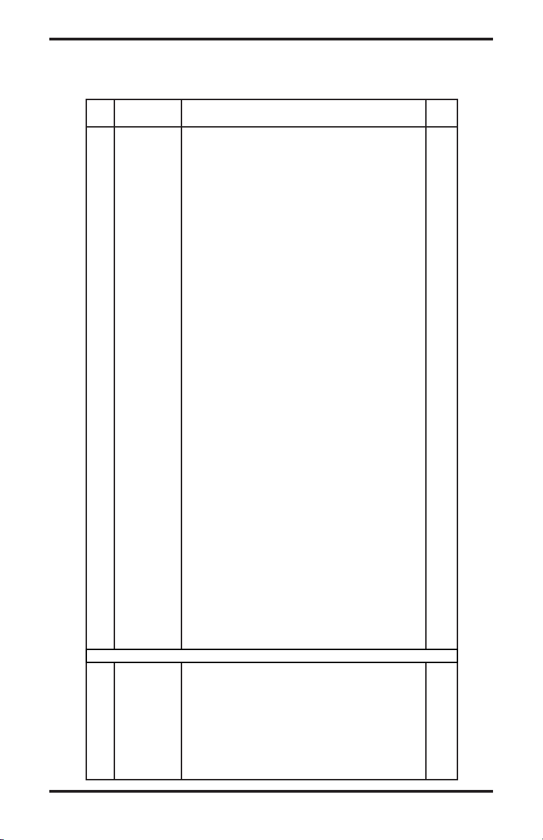
2. To light the pilot:
a) Press control knob and turn to the PILOT
position.
b) Hold control knob in and press ignition
button until the pilot lights.
c) Keep control knob pressed in for 30 sec
onds to heat thermocouple.
d) Release control knob and pilot should re
main lit. Note: To visually check ignition
of pilot, slide viewing hole cover to either
side (see Figure 9).
e) Once pilot flame stays on, close viewing
hole cover.
CAUTION: Do not attempt
to slide the viewing hole cover
when the main burner is lighting,
operating or hot.
3. To match light pilot, rotate the viewing hole
cover and apply flame to the pilot burner while
holding knob in for 20 seconds or until pilot
remains lit when knob is released.
4. Set the heat level.
a) Press and turn control knob to the HIGH
position. Burner will light immediately.
b) Press and turn control knob to the desired
heat level. Note: While in use, burner
flame should be mainly blue in appearance
with a small amount of yellow.
IMPORTANT: Smoke and odor (not a gas odor)
emission may occur in the first 15 minutes of use.
Run heater at high setting for at least 15 minutes
to eliminate this problem.
WARNING: If you smell gas
while in use, immediately press
and turn control knob to the OFF
position to shutdown heater.
-
STOP
1. Press and turn control knob to the PILOT
position. Burner will extinguish but pilot will
stay on.
2. To extinguish pilot, press and turn control
knob to the OFF position.
3. Turn off gas supply.
4. Do not attempt to relight the heater for 5
minutes after propane/LP cylinder valve has
been closed.
-
RESTART HEATER
1. Turn gas control knob to the OFF position.
2. Wait 5 minutes.
3. Restart following
Start procedure.
STORAGE
1. Allow at least 45 minutes for heater to cool
down after using.
2. Store heater upright in a sheltered area away
from inclement weather and dust.
3. If desired, cover heater after heater has
cooled.
4. If heater is not to be used for an extended period
of time, disconnect and remove propane/LP
gas cylinder and store in accordance with the
Standard for Storage and Handling of Liquefied
Petroleum Gases, ANSI/INFPA 58.
Viewing Hole
and Cover
Figure 9 - Viewing Hole and Cover
8
www.desatech.com
114144-01E

SERVICING
To assure safety, proper function and longevity
of the heater, regular maintenance is required.
The frequency of maintenance will depend on the
usage of the unit. Review the following concerning the criteria for a properly functioning heater.
Failing to follow proper, regular maintenance will
void warranty.
A hazardous condition may result if a heater is
used that has been modified or is not functioning
properly. When the heater is working properly:
• The flame is contained within the heater.
• The flame is essentially blue with perhaps some
yellow tipping.
• There is no strong disagreeable odor, eye burn
ing or other physical discomfort.
• There is no smoke or soot internal or external
to the heater.
• There are no unplanned or unexplained shut
downs of the heater.
The parts lists and wiring diagram show the heater
as it was constructed. Do not use a heater which is
different from that shown. In this regard, use only
the hose, regulator and cylinder connection fitting
(called a POL fitting) supplied with the heater.
IMPORTANT: Do not use alternates. For this
heater, the regulator must be set as shown in Speci
fications, page 2. If there is any uncertainty about
the regulator setting, have it checked.
REPLACEMENT PARTS
WARNING: Use only original
replacement parts. This heater
must use design-specific parts.
Do not substitute or use generic
parts. Improper replacement
parts could cause serious or fatal injuries. This will also protect
your warranty coverage for parts
replaced under warranty.
When calling DESA Heating Products, have ready
• your name
• your address
• model number of your heater
• how heater was malfunctioning
• purchase date
PARTS NOT UNDER WARRANTY
Contact authorized dealers of this product. If
they canʼt supply original replacement part(s),
either contact your nearest Parts Central (listed in
Authorized Service Center booklet) or call DESA
Heating Products at 1-866-672-6040 for referral
information.
When calling DESA Heating Products, have ready
-
• model number of your heater
• the replacement part number
TECHNICAL SERVICE
A heater which is not working right must be repaired, but only by a trained, experienced service
person. To find the service center closest to you,
or if you have further questions about this heater,
contact DESA Heating Productsʼ Technical Service
Department at 1-866-672-6040. When calling,
please have your model and serial numbers of
your heater ready.
-
You can also visit DESA Heating Productsʼ Techni
cal Service web site at www.desatech.com.
You may also obtain in-warranty or out-of-war
ranty service by taking the product to your local
service center.
-
-
PARTS UNDER WARRANTY
Contact authorized dealers of this product. If they
canʼt supply original replacement part(s), either
contact your nearest Parts Central or call DESA
Heating Productsʼ Technical Service Department
at 1-866-672-6040.
114144-01E
www.desatech.com
9

ILLUSTRATED PARTS BREAKDOWN
1
21
20
10
22
29
28
27
25
24
26
23
9
7
6
5
4
3
8
2
11
12
17
16
19
18
15
14
13
14
(Model
SPC-54PHS
Only)
MODELS
SPC-54PHW, SPC-54PHB, SPC-54PHT AND SPC-54PHS
10
www.desatech.com
114144-01E
PARTS LIST
This list contains replaceable parts used in your heater. When ordering parts, follow the instructions
listed under Replacement Parts on page 9 of this manual.
KEY PART
NO. NUMBER DESCRIPTION QTY.
1 114133-01 Reflector 1
2 114102-01 Emitter Assembly 1
3 114104-01 Burner Assembly 1
4 114113-01 Burner Cover Bottom 1
5 114126-01 Orifice, Main Burner 1
6 114130-01 Adiabatic Plate 1
7 114138-01 Tip Switch 1
8 114140-01 Fuel Tube 1
9 114142-01 Valve 1
10 114115-01 Valve Housing Cover 1
11 114129-01 Front Cover Panel 1
114129-02 Front Cover Panel (SPC-54PHS only) 1
12 114136-01 Shield, Pilot Wind 1
13 114105-01 Pilot Assembly 1
14 102445-01 Piezo Ignitor Kit 1
114187-01 Electronic Ignitor Kit (SPC-54PHS only) 1
15 114117-01 Ignition Wire 1
16 114141-01 Pilot Tube 1
17 114180-01 Knob 1
18 114114-01 Valve Cover Base 1
19 114112-01 Valve Mounting Bracket 1
21 114101-01 Fuel Line Adaptor 1
22 114139-01 Tank Cover Assembly (White) 1
114139-02 Tank Cover Assembly (Bronze) 1
114139-03 Tank Cover Assembly (Black) 1
114139-04 Tank Cover Assembly (Stainless Steel) 1
23 114116-01 Guards, Rubber Handle 1
24 114103-01 Manifold Assembly (Fuel line, hose, regulator) 1
25 114132-01 Pole (White) 1
114132-02 Pole (Bronze) 1
114132-03 Pole (Stainless Steel) 1
114132-04 Pole (Black) 1
26 114137-01 Pole Support (White) 1
114137-02 Pole Support (Bronze) 1
114137-03 Pole Support (Black) 1
27 114108-01 Base Legs (Black) 3
114108-02 Base Legs (Bronze) 3
114108-03 Base Legs (White) 3
28 114107-01 Base (Black) 1
114107-03 Base (Bronze) 1
114107-04 Base (White) 1
29 114131-01 Ballast Plate 1
PARTS AVAILABLE - NOT SHOWN
114106-01 Wheel Assembly 1
114122-01 Model Decal SPC-54 1
114123-01 Operating Instruction Label (English) 1
114124-01 Warning Label (English) 1
114124-02 Warning Label (Spanish) 1
114124-03 Warning Label (French) 1
114124-04 Operating Instruction Label (Spanish) 1
114124-05 Operating Instruction Label (French) 1
114127-01 Hardware Package 1
114144-01E 11
www.desatech.com

WARRANTY AND REPAIR SERVICE
KEEP THIS WARRANTY
Model
Serial No.
Date of Purchase
LIMITED WARRANTY
DESA Heating Products warrants this product and any parts thereof, to be free from defects in materials and
workmanship for one (1) year from the date of first purchase when operated and maintained in accordance with in
structions. This warranty is extended only to the original retail purchaser, when proof of purchase is provided.
This warranty covers only the cost of parts and labor required to restore the product to proper operating condition.
Transportation and incidental costs associated with warranty repairs are not reimbursable under this warranty.
Warranty service is available only through authorized dealers and service centers.
This warranty does not cover defects resulting from misuse, abuse, negligence, accidents, lack of proper main
tenance, normal wear, alteration, modification, tampering, contaminated fuels, repair using improper parts, or
repair by anyone other than an authorized dealer or service center. Routine maintenance is the responsibility of
the owner.
THIS EXPRESS WARRANTY IS GIVEN IN LIEU OF ANY OTHER WARRANTY EITHER EXPRESSED OR
IMPLIED, INCLUDING WARRANTIES OF MERCHANTABILITY AND FITNESS FOR A PARTICULAR
PURPOSE.
DESA Heating Products assumes no responsibility for indirect, incidental or consequential damages. Some states
do not allow the exclusion or limitation of incidental or consequential damages or limitations or exclusions may
not apply to you. This Limited Warranty gives you specific legal rights and you may also have other rights which
vary from state to state.
This warranty does not cover discoloration due to operation of heater. We reserve the right to amend these specifications at any time without notice. The only warranty applicable is our standard written warranty. We make no other
warranty, expressed or implied.
WARRANTY SERVICE
Should your heater require service, return it to your nearest authorized service center. Proof of purchase must be
presented with the heater. The heater will be inspected. A defect may be caused by faulty materials or workmanship.
If so, DESA Heating Products will repair or replace the heater without charge.
REPAIR SERVICE
Return the heater to your nearest authorized service center. Each Service Center is independently owned and operated.
Repairs not covered by the warranty will be billed at standard prices. We reserve the right to amend these specifications
at any time without notice.
For information about this warranty write:
-
-
2701 Industrial Drive
P.O. Box 90004
Bowling Green, KY 42102-9004
ATTN: Customer Service Department

Calentador de patio de propano o gas LP
Manual del propietario
86NH
ADVERTENCIA: para uso
en exteriores solamente
MODELOS SPC-54PHW, SPC-54PHB, SPC-54PHT Y SPC-54PHS
IMPORTANTE: lea y comprenda este manual antes de
ensamblar, encender o dar servicio al calentador. El uso
inadecuado del calentador puede causar lesiones graves. Conserve este manual para referencias futuras.
PARA SU SEGURIDAD
No guarde ni utilice gasolina u otros vapores y líquidos
inflamables cerca de este aparato ni de cualquier otro.
PARA SU SEGURIDAD
Si percibe olor a gas:
1. Cierre el suministro de gas al aparato.
2. Extinga las llamas al descubierto.
3. Si el olor persiste, llame inmediatamente al distribuidor de gas.
Guarde este manual para referencia futura.
Para obtener más información, visite www.desatech.com

ADVERTENCIA: La instalación, ajuste, alteración,
servicio o mantenimiento inadecuados pueden causar
lesiones, daños a la propiedad o la muerte. Lea las instrucciones de instalación, operación y mantenimiento
minuciosamente antes de instalar o dar servicio a este
equipo.
Especificaciones .................................................. 2
Información de seguridad .................................... 2
Seguridad con propano o gas LP ........................ 4
Instrucciones de ensamblaje ............................... 5
Instrucciones de funcionamiento ......................... 7
Almacenamiento .................................................. 8
Reparaciones ...................................................... 8
Piezas de repuesto .............................................. 9
Servicio técnico ................................................... 9
Clasificación ilustrada de piezas y lista de piezas
Garantía y servicio de reparación ..................... 12
. 10
ESPECIFICACIONES
TABLA DE CONTENIDO
Clasificación 40.0000 BTU/h (11,7 kW)
Tipo de gas únicamente gas propano o LP
Presión del suministro de gas al regulador máxima 150 PSI (1034,2 kPa) mínima 5 PSI (34,5 kPa)
Presión del suministro de gas salida del regulador, 11 pulgadas de col. de agua (2,74 kPa)
Encendido encendido piezoeléctrico
Consumo de combustible 0,84 kg/h (1,86 lb/h)
Seguridad de llama válvula de gas operada por termopar
INFORMACIÓN DE SEGURIDAD
ADVERTENCIA: este produc-
to contiene y/o genera químicos
que el Estado de California
reconoce que causan cáncer,
defectos de nacimiento u otros
daños relacionados con la reproducción.
ADVERTENCIA: no usar
en residencias ni en vehículos
recreativos.
ADVERTENCIA: peligro de
incendio, quemaduras, inhala
ción y explosión. Mantenga los
combustibles sólidos, como ma
teriales de construcción, papel o
cartón a una distancia segura del
calentador según se recomienda
en las instrucciones. Nunca use
el calentador en espacios que
contengan o puedan contener
combustibles volátiles o gaseosos o productos como gasolina,
solventes, diluyente de pintura,
partículas de polvo o químicos
desconocidos.
-
-
2
www.desatech.com
114144-01E

INFORMACIÓN DE SEGURIDAD
Continuación
No podemos prever todos los usos que se le pueden dar
a nuestros calentadores. Verifique con la autoridad local
de seguridad contra incendios si tiene preguntas acerca
del uso de calentadores. Otras normas rigen el uso de
gases combustibles y productos que producen calor
para usos específicos. Las autoridades locales pueden
informarle acerca de éstas.
Intoxicación con monóxido de carbono: de “caldeo
directo” significa que todos los productos de combustión
entran al espacio que se está calentando. Aun cuando este
calentador opera con una eficiencia de combustión muy
cercana al 100%, produce cantidades pequeñas de monóxido de carbono. El monóxido de carbono afecta más
a algunas personas que a otras. Los síntomas iniciales de
la intoxicación con monóxido de carbono se parecen a los
de la gripe, con dolores de cabeza, mareos y/o náusea. Si
usted presenta estos síntomas, es posible que el calentador
no esté funcionando correctamente. ¡Respire aire fresco
inmediatamente! Compruebe que haya ventilación
adecuada y haga que reparen el calentador.
Gas propano: el gas propano es inodoro. Al gas pro-
pano se le agrega un agente oloroso. El olor le ayuda
a detectar las fugas de gas propano. Sin embargo, el
olor que se añade al gas propano puede desvanecerse.
Es posible que haya gas propano presente aunque no
haya ningún olor.
Este es un calentador de propano de caldeo directo. El
propano es más pesado que el aire. Si hay una fuga de
propano en una de las conexiones o niples, éste fluirá
hacia el piso y se acumulará ahí con el aire circundante,
lo que formará una mezcla que es potencialmente explosiva. Obviamente, las fugas de propano se deben evitar,
por lo que debe instalar el suministro de propano con el
mayor cuidado posible. Lea Seguridad con propano o
gas LP en la página 4 para obtener información adicional
sobre cómo detectar fugas de propano. Revise las nuevas
conexiones en busca de fugas utilizando una solución de
agua y jabón y siga todas las instrucciones de conexión
contenidas en este manual. Además, pida consejo a su
distribuidor de gas propano sobre la instalación del
suministro y aplicación de propano y pida también que
la revise en caso que haya alguna duda.
Si el calentador se va a hacer funcionar en presencia de otras personas, es responsabilidad del
usuario hacer que dichas personas se familiaricen
con las precauciones e instrucciones de seguridad,
así como con los peligros asociados.
Asegúrese de leer y comprender todas las adver
tencias. Conserve este manual para consulta. Es
su guía para la operación segura y correcta de
este calentador.
1.
Revise el calentador completamente para ver si
presenta daños. NO haga funcionar un calentador dañado.
-
2. NO modifique el calentador ni haga funcionar
un calentador que ha sido sometido a modificaciones de su condición original.
3. Utilice únicamente gas propano o LP.
4.
Utilice únicamente suministros de propano con EXTRACCIÓN DE VAPORES. El cilindro de propano
se debe de configurar para la extracción de vapores,
de acuerdo a Ensamblaje de botellas pequeñas de
propano de la Asociación de gas comprimido. Si
tiene alguna pregunta acerca de la extracción de
vapores, pregunte al distribuidor de propano.
5. Nunca utilice el calentador si el contrapeso no
está ensamblado en la base. La base debe contar
con peso para evitar que se vuelque.
6. Use sólo el ensamblaje de regulador y manguera
que se incluye con el calentador.
7.
Inspeccione el ensamblaje de la manguera antes de
cada uso del calentador. Si hay rozaduras o desgaste
excesivos, o si la manguera tiene cortaduras, reemplácela con el ensamblaje de manquera que aparece
en la lista de piezas antes de usar el calentador.
8.
Este calentador es PARA USO EN EXTERIORES SOLAMENTE; aun así, asegúrese de que haya suficiente
aire fresco para la ventilación. No lo utilice dentro de
edificios, cocheras u otros espacios cerrados.
9.
Si en cualquier momento percibe olor a gas, DETENGA INMEDIATAMENTE el funcionamiento
del aparato hasta que la fuente de donde proviene el
gas haya sido localizada y reparada. Lea Seguridad
con propano en la página 4 para obtener información
adicional sobre cómo detectar fugas de propano.
10. Instale el calentador de manera que no esté
expuesto a rocío de agua, lluvia o goteras.
11. Mantenga las distancias mínimas con respecto a
las personas o a los materiales comunes combustibles (como el papel) de 1,10 m (3,6 pies) con
respecto a la parte superior y de 0,61 cm (2 pies)
con respecto al reflector.
12. Hágalo funcionar únicamente sobre una superficie estable y nivelada.
13. No rocíe aerosoles cerca del calentador mientras
éste esté funcionando, ni poco después de que
deje de funcionar.
14. No limpie el calentador con limpiadores combus
tibles o corrosivos. Use agua tibia jabonosa.
15. Revise que en los quemadores y ductos de aire
de ventilación pueda fluir libremente el aire y
que estén libres de obstrucciones. En estas áreas
comúnmente se acumulan telarañas que pueden
producir condiciones de peligro, dañar el calentador y causar que sea inseguro operarlo. Debe
de revisar el calentador si se presenta cualquiera
de las siguientes condiciones:
a) Olor a gas, aunado a un coloramiento predo
minantemente amarillo en las puntas de las
llamas del quemador.
b) El calentador no alcanza la temperatura
establecida.
-
-
114144-01E
www.desatech.com
3

INFORMACIÓN DE SEGURIDAD
Continuación
c) El brillo en el quemador no es uniforme.
d) Se escuchan chasquidos del quemador duran
te uso normal, aparte de cuando se apaga.
16. Use solamente agua jabonosa (1 parte de
detergente líquido para platos y 3 partes de
agua) para revisar que no haya fugas cada
vez que se conecta un cilindro de propano.
Las burbujas indican una fuga.
17. No ajuste el regulador de gas. Si no está seguro
del tipo de gas o de la presión de su aparato,
llame a un agente de servicio capacitado.
18.
Ponga la perilla de control en la posición de “APAGADO” cuando no esté usando el calentador.
19. Siempre desconecte el suministro de gas
cuando el calentador esté “APAGADO”.
20. No lo mueva, manipule ni repare mientras está
caliente o encendido.
21. Permita que pasen 45 minutos después de
usarse para que se enfríe el calentador antes
de intentar moverlo.
22. No haga funcionar este aparato bajo condicio
nes de mucho viento. La velocidad máxima
permisible es de 16 km/h (10 mph).
23.
No haga funcionar este aparato en condiciones
de temperatura por debajo de los 5° C ( 40° F).
24. Mantenga el calentador alejado de áreas donde
se almacenen o se usen líquidos, vapores o
sólidos inflamables.
25. Si el calentador se opera en áreas con aire
salado, será necesario limpiarlo con más fre
cuencia; de lo contrario, la longevidad de la
unidad se deteriorará rápidamente. Use agua
jabonosa para limpiar la unidad.
26. Los materiales o artículos que se almacenen
debajo del calentador estarán sometidos a un
calor radiante y pueden sufrir daños graves.
27. Úsese sólo de acuerdo a los códigos locales o,
a falta de dichos códigos, de acuerdo al Código
Nacional de Gas Combustible, ANSI Z223.1
Cualquier resguardo u otro dispositivo de protección que haya sido
retirado para fines de servicio debe
volver a colocarse antes de hacer
funcionar el calentador.
Las temperaturas de las superficies
se calientan mucho cuando el calen
tador está en funcionamiento. Los
niños y los adultos deben permane
cer alejados para evitar quemaduras
o igniciones de la ropa.
-
-
Los niños menores deben ser supervisados muy cuidadosamente
cuando se encuentren en el área
del calentador.
-
La ropa u otros materiales infla
mables no se deben colgar en el
calentador, ni colocarse sobre éste
o cerca de él.
Una persona de servicio capacitada
debe realizar la instalación y las re
paraciones. El calentador debe ser
inspeccionado antes de su uso y al
menos una vez al año por una persona
de servicio capacitada. Es posible
que sea necesario realizar limpiezas
más frecuentes. Es imperativo que los
compartimientos de control, quema
dores y pasajes de aire circulante del
calentador se mantengan limpios.
-
PRECAUCIÓN: Se debe utilizar
el regulador de presión de gas que
se incluye con este aparato. Este
regulador está calibrado para una
presión de salida de 2,74 kPa (11
pulgadas de columna de agua).
-
SEGURIDAD CON
PROPANO O GAS LP
ADVERTENCIA: para uso en
exteriores solamente.
PELIGRO DE ASFIXIA
• No utilice este calentador para la calefac-
.
ción de lugares de alojamiento humano.
• No lo utilice en áreas sin ventilación.
• No se debe obstruir el flujo de aire para
combustión y ventilación.
• Se debe procurar el aire necesario para
ventilación a fin de que se cumplan los
requisitos de aire para combustión del
calentador que se está usando.
• Consulte las Especificaciones en la página
2, la placa de datos del mismo o comuníquese con DESA Heating Products para
determinar los requisitos de ventilación
de aire para combustión del calentador.
• La falta de aire para una ventilación adecuada producirá una combustión incorrecta.
-
-
-
4
www.desatech.com
114144-01E

SEGURIDAD CON
PROPANO O GAS LP
Continuación
•
La combustión incorrecta puede generar
intoxicaciones por monóxido de carbono que
pueden resultar en lesiones graves o en la
muerte. Los síntomas de la intoxicación con
monóxido de carbono pueden incluir dolores
de cabeza, mareos y dificultad para respirar.
INSTRUCCIONES DE
ENSAMBLAJE
Herramientas necesarias:
• Destornillador Phillips #2 1
• Llave inglesa 2
Inspeccione los componentes del calentador en busca
de posibles daños sufridos durante el transporte. Si
se encuentra algún daño, informe inmediatamente
al distribuidor. Revíselo para asegurarse que todos
los componentes estén incluidos con el calentador
(consulte las páginas 10 y 11).
ENSAMBLAJE DEL POSTE
1. Fije las patas a la base usando dos pernos, dos
arandelas de presión y dos tuercas (consulte la
figura 1). Introduzca los pernos a través de las
patas y a través de la parte superior de la base.
Fije las arandelas de presión y las tuercas desde la
parte inferior de la base. Apriete sólo con la mano.
Repita lo anterior para cada pata. No apriete las
tuercas completamente hasta el siguiente paso.
2. Fije seguramente el soporte del poste a las patas
usando dos pernos, dos arandelas de presión y
dos tuercas. Repita lo anterior para cada pata.
Apriete los pernos y las tuercas de los pasos 1 y
2 con una llave.
3. Fije el contrapeso a la base usando un perno
largo, una arandela de presión y una tuerca
(consulte la figura 1).
4.
Inserte el tubo múltiple en el soporte del poste
(consulte la figura 2). Inserte el ensamblaje del tubo
múltiple a través del poste pasándolo por el orificio
en el soporte del poste. Nota: asegúrese de que el
ensamblaje de regulador y manguera que está conectado al tubo múltiple no se doblen o se plieguen
durante la instalación u operación del calentador.
5. Fije el poste al soporte del poste (figura 3). Coloque el poste en el conector central del soporte del
poste. Apriete los seis tornillos con la llave Allen
hexagonal incluida con el calentador. Nota: los
tornillos se enroscan dentro del soporte del poste.
6. Coloque la cubierta del cilindro de propano o gas
LP en el ensamblaje de la base (consulte la figura
4). Deslice la cubierta del cilindro de propano o
gas LP sobre el poste y el soporte del poste. Asegúrese de que la cubierta del cilindro de propano
o gas LP quede nivelada sobre la base.
Soporte
del poste
Patas
Base
Contrapeso
Figura 1. Ensamblaje de la base
Ensamblaje
del tubo
múltiple
Soporte
del
poste
Figura 2. Instalación del ensamblaje del
tubo múltiple
Poste
Soporte
del
poste
Figura 3. Poste al soporte del poste
Poste
Cubierta del
cilindro de
propano o
gas LP
Base
Figura 4. Cubierta del cilindro de
propano o gas LP
114144-01E
www.desatech.com
5

INSTRUCCIONES DE
ENSAMBLAJE
Continuación
ENSAMBLAJE DEL CONTROL Y
DEL QUEMADOR
La conexión entre la línea de combustible y el quemador es de tipo conexión rápida. Siga estas instrucciones
para el ensamblaje mientras consulta la figura 5:
1. Extraiga el tubo múltiple del extremo superior
del poste.
2. Deslice o mueva el cuello de conexión rápida
del tubo múltiple hacia atrás.
3. Fije el tubo múltiple al ensamblaje de control y
quemador empujando la conexión del ensam
blaje de control y quemador completamente a
través del tubo múltiple.
4. Asegúrese de que el ensamblaje del tubo múltiple y
del quemador queden conectados correctamente.
5. Suelte el cuello de conexión rápida del tubo múlti
ple que había empujado hacia atrás en el paso 2.
6. Coloque el ensamblaje de control y quemador
en el poste.
Ensamblaje
de control y
quemador
Ensamblaje
del tubo
múltiple
Poste
Figura 5. Conexión del ensamblaje del
tubo múltiple al ensamblaje de control y
quemador
REVISE QUE NO HAYA FUGAS
IMPORTANTE: se debe revisar el calentador en
busca de fugas antes de proceder con el ensambla
je. Use solamente una solución de agua y jabón.
NO USE UNA LLAMA.
Gire la perilla de control hacia la posición de OFF (APAGADO). Conecte el regulador al cilindro de propano o
gas LP de manera segura. Abra la válvula del cilindro de
propano o gas LP Aplique una solución de agua y jabón
a las conexiones del el tubo múltiple, del quemador y
del ensamblaje de control. La formación de burbujas
indicará una fuga. Si encuentra alguna fuga, apague la
válvula del cilindro de propano o gas LP, quite el tubo
múltiple y revise y limpie la conexión. Vuelva a conectar
el tubo múltiple y revise nuevamente si hay fugas.
Una vez que haya completado la revisión de fugas y
que no encuentre ninguna, cierre la válvula del cilin
dro de propano o gas LP y desconecte el regulador
del cilindro de propano o gas LP. Quite el cilindro de
propano o gas LP y proceda al paso siguiente.
POSTE Y ENSAMBLAJE DEL
CONTROL Y QUEMADOR
Fije el poste al ensamblaje de control y quemador
(consulte la figura 6). Alinee los tres orificios. Inserte un perno pequeño en cada uno de los orificios
y apriételos usando un destornillador Phillips #2.
-
-
Figura 6. Fijación del ensamblaje de
control y quemador al poste
SOPORTE DEL POSTE Y PLACA DE
SUJECIÓN DEL TUBO MÚLTIPLE
1. Encuentre el orificio roscado debajo del soporte
del poste. Este orificio sirve para fijar la placa de
sujeción del tubo múltiple (consulte la figura 7).
2. Alinee los orificios en la placa de sujeción del
tubo múltiple con los orificios roscados en el
soporte de poste.
3. Asegúrese que la placa de sujeción del tubo
múltiple se encuentre orientada hacia abajo
(figura 7).
4. Use un perno para apretar la placa de sujeción
del tubo múltiple al soporte del poste usando
un destornillador Phillips #2.
5. Gire la placa de sujeción del tubo múltiple de
manera que sujete a este último en su sitio.
6. Apriete el perno de manera que la placa de
-
sujeción del tubo múltiple no se mueva.
Placa de
sujeción del
tubo múltiple
Figura 7. Fijación de la placa de sujeción
del tubo múltiple al soporte del poste
-
6
www.desatech.com
114144-01E

INSTRUCCIONES DE
ENSAMBLAJE
Continuación
DOMO Y EMISOR
Coloque cuidadosamente el ensamblaje del calentador sobre un costado usando una de las piezas
de espuma de estireno del embalaje, de manera
que la parte superior del calentador quede alzada.
Alinee los orificios en el domo con los pernos
roscados en la cubierta del emisor. Fije el domo
al emisor usando tres tuercas ciegas. Apriete con
una llave inglesa. Vuelva a colocar el calentador
en posición vertical.
Figura 8. Fijación del domo al emisor
INSTRUCCIONES DE
FUNCIONAMIENTO
ADVERTENCIA: si percibe
olor a gas:
• Cierre el suministro de gas al
aparato.
• Apague todas las llamas al
descubierto.
•
Si el olor persiste, llame inmediatamente al distribuidor de gas.
Consulte las advertencias y precauciones de seguridad que comienzan
en la primera página de este manual
para obtener más información.
PREPARACIÓN PARA EL
FUNCIONAMIENTO
1. Revise el calentador para ver si sufrió algún daño
durante el transporte. Si se encuentra algún daño,
informe inmediatamente a la fábrica.
2. Siga toda la información de seguridad.
3. Revise y asegúrese de que la perilla de control
esté en la posición de OFF (APAGADO).
4. Coloque el cilindro de propano o gas LP dentro
de la base del cilindro. Conecte el regulador al
cilindro de propano o gas LP de manera segura.
5. Abra la válvula del cilindro. Aplique una so
lución de agua y jabón a la conexión entre el
regulador y el cilindro. La formación de burbujas
indicará una fuga.
6. Si encuentra alguna fuga, cierre la válvula
del cilindro de propano o gas LP y desarme la
conexión que tiene la fuga. Revise y limpie la
conexión. Vuelva a conectar el regulador y revise
nuevamente si hay fugas.
INICIO
1. Purgue la línea de gas que conecta al ensamblaje
del piloto. Presione y gire la perilla de control a
la posición de ALTO y manténgala presionada
durante 1 ó 2 minutos.
cilindro nuevo o uno que se rellenó, el calenta
dor, debrá purgarse nuevamente.
2. Para encender el piloto:
a) Presione la perilla de control y gírela hasta
la posición de PILOT (PILOTO).
b) Mantenga presionada la perilla de control y
presione el botón de encendido hasta que se
encienda el piloto.
c) Mantenga presionada la perilla durante 30
segundos para calentar el termopar.
d) Suelte la perilla de control; el piloto se deberá
mantener encendido.
sualmente si se encendió el piloto, deslice la
cubierta del orifico de observación a un lado
(consulte la figura 9).
e) Una vez que el piloto se mantenga encendido,
cierre la cubierta del orificio de observación.
Nota: cuando instale un
Nota: para revisar vi-
PRECAUCIÓN: no intente deslizar
la cubierta del orificio de observación mientras el quemador principal
se esté encendiendo, ni mientras
esté encendido o esté caliente.
Orificio de
visualización
y su cubierta
Figura 9. Orificio de visualización y su
cubierta
-
-
114144-01E
www.desatech.com
7

INSTRUCCIONES DE
FUNCIONAMIENTO
Continuación
3. Para encender el piloto con un fósforo, gire la
cubierta del orificio de visualización y aplique
la llama al quemador del piloto mientras
mantiene presionada la perilla durante 20 segundos, o bien, hasta que el piloto se mantenga
encendido cuando suelte la perilla.
4. Ajuste el nivel de calor.
a) Presione y gire la perilla de control hasta la
posición de HIGH (ALTO). El quemador se
encenderá inmediatamente.
b)
Presione y gire la perilla de control al nivel
de calor deseado. Nota: mientras se esté
usando, el color de las flamas del quemador
debe de ser predominantemente azul, con un
poco de amarillo.
IMPORTANTE: se pueden producir humo y un olor
(no a gas) durante los primeros 15 minutos que está
en funcionamiento. Haga funcionar el calentador en
la posición de alto durante 15 minutos para eliminar
este problema.
ADVERTENCIA: si detecta olor
a gas mientras está funcionando,
inmediatamente presione y gire
la perilla de control a la posición
OFF (APAGADO) para apagar el
calentador.
DETENER
1.
Presione y gire la perilla de control hasta la
posición de PILOT (PILOTO). El quemador se
apagará, pero el piloto se mantendrá encendido.
2.
Para apagar el piloto, presione y gire la perilla de
control hasta la posición de OFF (APAGADO).
3. Cierre el suministro de gas.
4. No intente volver a encender el calentador
dentro de los 5 minutos posteriores al cierre de
la válvula del cilindro de propano o gas LP.
VUELVA A ENCENDER EL CALENTADOR
1. Gire la perilla de control de gas a la posición
de
OFF (APAGADO)
2. Espere 5 minutos.
3. Vuelva a encender siguiendo el procedimiento
de Inicio.
.
ALMACENAMIENTO
1. Permita que transcurran al menos 45 minutos
para que se enfríe el calentador después de
utilizarlo.
2. Almacene el calentador en posición vertical en
una área protegida contra las inclemencias del
tiempo y el polvo.
3. Si así lo desea, cubra el calentador una vez que
éste se haya enfriado.
4.
Si el calentador no se va a usar por un periodo
extendido de tiempo, desconecte y retire el
cilindro de propano o gas LP y almacénelo de
acuerdo a la Norma de almacenamiento y manejo
de gas licuado de petróleo, ANSI/INFPA 58
.
REPARACIONES
Para fines de seguridad, funcionamiento correcto
y longevidad del calentador, es necesario un mantenimiento periódico. La frecuencia del manteni
miento dependerá del uso de la unidad. Revise la
siguiente información acerca de los criterios para
un calentador que funciona correctamente. Si no
proporciona el mantenimiento correcto y periódico,
la garantía se anulará.
Si se utiliza un calentador que ha sido modificado o
que no funciona correctamente, se puede generar una
condición de peligro. Cuando el calentador funciona
correctamente:
• La flama queda contenida dentro del calentador.
• La flama es primordialmente de color azul y puede
tener un poco de amarillo en la punta.
• No se experimentan olores desagradables e inten
sos, ardor de ojos ni otras molestias físicas.
•
No hay humo ni hollín dentro o fuera del calentador
• El calentador no se apaga repentina e inexplica
blemente.
Las listas de piezas y el diagrama de cableado
muestran la forma en la que el calentador está cons
truido. No utilice un calentador que sea diferente
del que se muestra. A este respecto, utilice sólo la
manguera, el regulador y el niple de conexión al
cilindro (conocido como niple de rosca invertida)
incluidos con el calentador.
IMPORTANTE: no use otras alternativas. Para
este calentador, el regulador se debe instalar como
se muestra en las Especificaciones en la página
2. Si tiene dudas acerca de la configuración del
regulador, haga que la revisen.
-
-
.
-
-
8
www.desatech.com
114144-01E

PIEZAS DE REPUESTO
ADVERTENCIA: use sólo
piezas de repuesto originales.
Este calentador debe usar piezas
diseñadas específicamente. No
las sustituya ni use piezas genéricas. El uso de piezas de repuesto
inadecuadas puede ocasionar
lesiones graves o fatales. Esto
también protegerá la cobertura
de su garantía para piezas reemplazadas con garantía.
PIEZAS CON GARANTÍA
Póngase en contacto con distribuidores autorizados
de este producto. Si ellos no le pueden proveer
las piezas originales de reemplazo, póngase en
contacto ya sea con su central de piezas más
cercana o llame al departamento de servicio
técnico de DESA Heating Products al teléfono
1-866-672-6040.
Cuando llame a DESA Heating Products, tenga listo:
• su nombre
• su dirección
• número del modelo de su calentador
• cómo se presentó el malfuncionamiento de su
calentador
• la fecha de compra
PIEZAS SIN GARANTÍA
Póngase en contacto con distribuidores autorizados
de este producto. Si ellos no pueden suministrar
piezas de repuesto originales, comuníquese con la
Central de piezas más cercana (listada en el folleto
de Centros de servicio autorizados), o bien, llame
a DESA Heating Products al 1-866-672-6040 para
obtener información de referencia.
Cuando llame a DESA Heating Products, tenga listo:
• número del modelo de su calentador
• el número de la pieza de reemplazo
SERVICIO TÉCNICO
Si un calentador no funciona correctamente debe
ser reparado, pero sólo puede hacerlo una persona
capacitada de servicio y con experiencia. Para en
contrar el centro de servicio más cercano, o si tiene
más preguntas acerca del calentador, comuníquese
con el departamento de servicio técnico de DESA
Heating Products, al 1-866-672-6040. Al llamar,
tenga a la mano los números de modelo y serie
de su calentador.
También puede visitar el sitio web de servi
cio técnico de DESA Heating Products en
www.desatech.com
También puede recibir servicio, cubierto o no
cubierto por la garantía, si lleva el producto al
centro de servicio local.
.
-
-
114144-01E
www.desatech.com
9

CLASIFICACIÓN ILUSTRADA DE PIEZAS
1
21
20
10
22
29
28
27
25
24
26
23
9
7
6
5
4
3
8
2
11
12
17
16
19
18
15
14
13
14
(Model
SPC-54PHS
Only)
MODELOS
SPC-54PHW, SPC-54PHB, SPC-54PHT Y SPC-54PHS
14 (sólo
modelo
SPC-54PHS)
10
www.desatech.com
114144-01E

Esta lista contiene las piezas reemplazables utilizadas en el calentador. Al hacer un pedido de piezas,
LISTA DE PIEZAS
siga las instrucciones listadas en Piezas de repuesto en la página 9 de este manual.
CLAVE PIEZA
CÓDIGO DE PARTE DESCRIPCIÓN CANT.
1 114133-01 Reflector 1
2 114102-01 Ensamblaje del emisor 1
3 114104-01 Ensamblaje del quemador 1
4 114113-01 Parte inferior de la cubierta del quemador 1
5 114126-01 Orificio, quemador principal 1
6 114130-01 Placa adiabática 1
7 114138-01 Interruptor de seguridad en caso de volcado 1
8 114140-01 Tubo de combustible 1
9 114142-01 Válvula 1
10 114115-01 Cubierta de la válvula 1
11 114129-01 Panel cobertor de la parte anterior 1
114129-02 Panel cobertor de la parte anterior (sólo SPC-54PHS) 1
12 114136-01 Protector del piloto contra viento 1
13 114105-01 Ensamblaje del piloto 1
14 102445-01 Paquete del encendedor piezoeléctrico 1
114187-01 Paquete del encendedor electrónico (sólo SPC-54PHS) 1
15 114117-01 Cable de ignición 1
16 114141-01 Tubo del piloto 1
17 114180-01 Perilla 1
18 114114-01 Base de la cubierta de la válvula 1
19 114112-01 Soporte de montaje de la válvula 1
21 114101-01 Adaptador de la línea de combustible 1
22 114139-01 Ensamblaje de la cubierta del tanque (blanco) 1
114139-02 Ensamblaje de la cubierta del tanque (bronce) 1
114139-03 Ensamblaje de la cubierta del tanque (negro) 1
114139-04 Ensamblaje de la cubierta del tanque (acero inoxidable) 1
23 114116-01 Resguardos, manija de hule 1
24 114103-01 Ensamblaje del tubo múltiple (línea de combustible,
manguera, regulador) 1
25 114132-01 Poste (blanco) 1
114132-02 Poste (bronce) 1
114132-03 Poste (acero inoxidable) 1
114132-04 Poste (negro) 1
26 114137-01 Soporte del poste (blanco) 1
114137-02 Soporte del poste (bronce) 1
114137-03 Soporte del poste (negro) 1
27 114108-01 Patas de la base (negro) 3
114108-02 Patas de la base (bronce) 3
114108-03 Patas de la base (blanco) 3
28 114107-01 Base (negro) 1
114107-03 Base (bronce) 1
114107-04 Base (blanco) 1
29 114131-01 Placa de contrapeso 1
PIEZAS DISPONIBLES. (NO SE MUESTRAN)
114106-01 Ensamblaje de ruedas 1
114122-01 Etiqueta adhesiva del modelo SPC-54 1
114123-01 Etiqueta de instrucciones de funcionamiento (en inglés) 1
114124-01 Etiqueta de advertencia (en inglés) 1
114124-02 Etiqueta de advertencia (en español) 1
114124-03 Etiqueta de advertencia (en francés) 1
114124-04 Etiqueta de instrucciones de funcionamiento (en español) 1
114124-05 Etiqueta de instrucciones de funcionamiento (en francés) 1
114127-01 Paquete de herramientas 1
114144-01E 11
www.desatech.com

GARANTÍA Y SERVICIO DE REPARACIÓN
GUARDE ESTA GARANTÍA
Modelo
N° de serie
Fecha de compra
GARANTÍA LIMITADA
DESA Heating Products (productos de calefacción de DESA) garantiza que este producto y todas sus piezas están
libres de defectos en los materiales y la mano de obra durante un (1) año a partir de la primera compra, siempre
que se hayan operado y mantenido de acuerdo con las instrucciones. Esta garantía es válida solamente para el
comprador minorista original, si se proporciona el comprobante de compra.
Esta garantía cubre exclusivamente el costo de las piezas y mano de obra que se necesiten para hacer que su
producto funcione adecuadamente de nuevo. La transportación y costos incidentales asociados con reparaciones
garantizadas no son reembolsables bajo esta garantía.
El servicio de garantía está disponible sólo a través de distribuidores autorizados y centros de servicio.
Esta garantía no cubre los defectos que resulten del uso inadecuado, abuso, descuido, accidentes, falta de mante
nimiento adecuado, uso normal, alteración, modificación, manipulación, combustibles contaminados, reparación
utilizando piezas inadecuadas, o reparación hecha por cualquiera que no sea un distribuidor autorizado o un centro
de servicio. El mantenimiento de rutina es responsabilidad del propietario.
ESTA GARANTÍA EXPRESA SE OTORGA EN LUGAR DE CUALQUIER OTRA GARANTÍA, YA SEA
EXPRESA O IMPLÍCITA, INCLUYENDO GARANTÍAS DE COMERCIABILIDAD Y APTITUD PARA UN
PROPÓSITO EN PARTICULAR.
DESA Heating Products no asume responsabilidad por daños consecuentes, indirectos o fortuitos. Algunos esta
dos no permiten la exclusión o limitación de daños incidentales o perjuicios, o es posible que las exclusiones no
sean aplicables a usted. Esta garantía limitada le otorga derechos legales específicos y posiblemente tenga otros
derechos que varían de un estado a otro.
Esta garantía no cubre la decoloración debida al funcionamiento del calentador. Nos reservamos el derecho de
modificar estas especificaciones en cualquier momento sin aviso previo. La única garantía aplicable es nuestra
garantía por escrito estándar. No otorgamos ninguna otra garantía, expresa o implícita.
SERVICIO DE GARANTÍA
Si su calentador requiere servicio, regréselo al centro de servicio autorizado más cercano. Se debe presentar una
prueba de compra con el calentador. El calentador será inspeccionado. Un defecto puede ser ocasionado por
materiales o mano de obra defectuosos. Si es así, DESA Heating Products reparará o reemplazará el calentador
sin ningún cargo.
SERVICIO DE REPARACIÓN
Devuelva el calentador al centro de servicio autorizado más cercano. Cada Centro de servicio tiene un propietario
y una operación independiente. Las reparaciones no cubiertas por la garantía se cobrarán a los precios regulares.
Nos reservamos el derecho de modificar estas especificaciones en cualquier momento sin aviso previo.
Para obtener información sobre esta garantía, escriba a:
-
-
2701 Industrial Drive
P.O. Box 90004
Bowling Green, KY 42102-9004, EE.UU.
ATTN: Customer Service Department

Appareil de chauffage de terrasse au propane ou au GPL
Manuel d’utilisation
86NH
AVERTISSEMENT :
pou r util isa tio n à
l’extérieur seulement.
MODÈLES SPC-54PHW, SPC-54PHB, SPC-54PHT ET SPC-54PHS
IMPORTANT : lisez et comprenez ce manuel avant d’assembler, d’allumer ou de réparer l’appareil de chauffage.
Une mauvaise utilisation de l’appareil de chauffage peut
causer des blessures graves. Conservez ce manuel
pour référence future.
POUR VOTRE PROTECTION
N’entreposez pas et n’utilisez pas d’essence, ni de vapeurs ou de liquides inflammables près de cet appareil
ou de tout autre appareil.
POUR VOTRE PROTECTION
Si vous sentez une odeur de gaz :
1. Coupez l’arrivée de gaz de l’appareil.
2. Éteignez les flammes nues.
3. Si l’odeur persiste, appelez immédiatement votre
compagnie de gaz.
Conservez ce mode d’emploi pour consultation future.
Pour plus de détails, visitez le site www.desatech.com

AVERTISSEMENT : Une installation fautive, un mauvais
ajustement ou une modification, une réparation ou un
entretien inapproprié peuvent entraîner des blessures, la
mort ou des dommages matériels. Lire attentivement les
instructions d’installation, d’utilisation et d’entretien avant
d’installer, de réviser ou de réparer cet appareil.
Spécifications ...................................................... 2
Informations relatives à la sécurité ...................... 2
Sécurité du propane et du GPL ........................... 4
Instructions d’assemblage ................................... 5
Notice d’utilisation ............................................... 7
Entreposage ........................................................ 8
Réparation ........................................................... 8
Pièces de rechange ............................................. 9
Service technique ................................................ 9
Vue détaillée des pièces
Service de garantie et de réparation ................. 12
et liste des pièces ...... 10
SPÉCIFICATIONS
TABLE DES MATIÈRES
Rendement 11,7 kW (40 000 Btu/h)
Type de gaz propane ou GPL uniquement
Pression du gaz à lʼentrée du détendeur maximum - 1034 kPa (150 psi), minimum - 34,5 kPa (5 psi)
Pression du gaz à la sortie du détendeur 2,74 kPa (11 po C.E.)
Allumage piézo-électrique
Consommation de carburant 0,84 kg/h (1,86 lb/h)
Sécurité de la flamme vanne de gaz contrôlée par thermocouple
INFORMATIONS RELATIVES À LA SÉCURITÉ
AVERTISSEMENT : cet appareil
contient ou produit des produits
chimiques déterminés par l’État de
Californie comme cancérigènes et
pouvant causer des malformations
congénitales et d’autres problè
-
mes reliés à la reproduction.
AVERTISSEMENT : cet appa-
reil n’est pas conçu pour usage
domestique ou dans les véhicules
de camping.
AVERTISSEMENT : danger
d’incendie, de brûlure, d’inhalation et d’explosion. Gardez
les produits combustibles solides comme les matériaux de
construction, le papier et les
cartons, à une distance sûre de
l’appareil de chauffage tel que
recommandé dans les instructions. N’utilisez jamais l’appareil
de chauffage dans des espaces
susceptibles de contenir des
combustibles volatils ou atmosphériques ou des produits tels
que de l’essence, des diluants,
du solvant à peinture, des particules de poussières ou des
produits chimiques inconnus.
2
www.desatech.com
114144-01D

INFORMATIONS RELATIVES
À LA SÉCURITÉ
Suite
Nous ne pouvons pas prévoir toutes les utilisations
possibles de nos appareils de chauffage. Vérifiez auprès
de votre responsable local de la sécurité-incendie si vous
avez des questions relatives à lʼutilisation de lʼappareil
de chauffage.
Dʼautres normes régissent lʼutilisation des gaz combus
tibles et des produits de chauffage pour des utilisations
particulières. Les autorités locales peuvent vous conseiller à propos de ces normes.
Empoisonnement au monoxyde de carbone :
le chauffage direct, tous les produits de combustion
entrent dans lʼespace chauffé. Bien que lʼefficacité de la combustion fournie par cet appareil de
chauffage atteigne près de 100 pour cent, il produit
quand-même de petites quantités de monoxyde de
carbone. Certaines personnes sont plus affectées par
le monoxyde de carbone que dʼautres. Les premiers
symptômes dʼun empoisonnement au monoxyde de
carbone ressemblent à la grippe avec des maux de
tête, des vertiges ou de la nausée. Si vous avez ces
symptômes, il se pourrait que lʼappareil de chauffage
ne fonctionne pas bien. Respirez tout de suite de
lʼair frais ! Vérifiez si la ventilation est suffisante et
faites réparer lʼappareil de chauffage.
Gaz propane : le gaz propane nʼa pas dʼodeur. Un
produit odorant est ajouté au gaz propane. Cette odeur
vous permet de détecter une fuite de propane. Cependant,
cette odeur ajoutée au propane peut se dissiper. Du gaz
propane peut être présent même sʼil nʼy a pas dʼodeur.
Cet appareil est un appareil à combustion directe de
propane. Le gaz propane est plus lourd que lʼair. Si
du propane fuit dʼun raccord ou dʼune connexion, il
sʼécoule vers le sol en sʼy accumulant avec lʼair ambiant pour former un mélange potentiellement explosif.
Évidemment, il faut éviter les fuites de propane en
installant lʼalimentation en propane avec le plus grand
soin. Lisez la rubrique Sécurité du propane et du GPL
à la page 4 pour des informations supplémentaires
sur la détection des fuites de propane. Recherchez la
présence de fuites sur les nouvelles connexions et les
reconnexions avec de lʼeau savonneuse et suivez toutes
les instructions relatives aux connexions notées dans
ce document. De plus, demandez des conseils à votre
fournisseur de propane pour lʼinstallation des conduites de gaz et les applications au propane; demandez-lui
de les vérifiez si vous avez des doutes.
Lorsque lʼappareil de chauffage fonctionne en pré
sence de personnes autres que lʼutilisateur, ce dernier
doit informer les personnes présentes des consignes de
sécurité, des précautions à prendre et des risques.
Lisez et comprenez tous les avertissements.
Conservez ce manuel pour consultation future. Il
vous permettra de faire fonctionner cet appareil de
chauffage correctement et en toute sécurité.
114144-01D
avec
www.desatech.com
1. Examinez soigneusement lʼappareil de chauffage
pour vérifier quʼil nʼest pas endommagé. Nʼutilisez PAS dʼappareil de chauffage endommagé.
2. NE modifiez PAS lʼappareil de chauffage et NE
faites PAS fonctionner un appareil de chauffage
dont la condition dʼorigine a été modifiée.
3. Nʼutilisez que du gaz propane ou du GPL.
4.
Nʼutilisez quʼune alimentation en propane composée pour le retrait de vapeur. La bouteille de propane
-
doit permettre le retrait de vapeur, en conformité
avec la norme de la Compressed Gas Association
sur lʼassemblage des petites bouteilles de propane.
Si vous avez des questions sur le retrait de vapeur,
communiquez avec votre fournisseur de propane.
5. Nʼutilisez pas lʼappareil de chauffage si le poids de
lestage nʼest pas monté dans le socle. Le socle doit
être lesté pour que lʼappareil ne se renverse pas.
6. Nʼutilisez que lʼassemblage de tuyau et de
détendeur fourni avec lʼappareil de chauffage.
7.
Inspectez lʼassemblage du tuyau avant chaque utilisation de lʼappareil de chauffage. Si le tuyau montre des
signes dʼusure excessive ou sʼil est fendu, remplacezle avec lʼassemblage de tuyau indiqué sur la liste des
pièces avant dʼutiliser lʼappareil de chauffage.
8. Cet appareil de chauffage NE DOIT ÊTRE UTILISÉ QUʼÀ LʼEXTÉRIEUR avec une ventilation
dʼair frais suffisante. Ne lʼutilisez pas dans des bâtiments, des garages ou dʼautres espaces fermés.
9. Si jamais vous détectez une odeur de gaz, ARRÊ
TEZ IMMÉDIATEMENT lʼappareil jusquʼà ce
que la source du gaz soit détectée et que la fuite
soit réparée. Lisez la rubrique Sécurité du propane
à la page 4 pour des informations supplémentaires
sur la détection des fuites de propane.
10. Installez lʼappareil de chauffage de sorte quʼil
soit à lʼabri des éclaboussures, de la pluie et de
lʼeau ruisselante.
11. Maintenez les distances minimales suivantes
avec les personnes et les matériaux combustibles
courants (comme le papier) : 1,10 m (3,6 pi) audessus et 0,61 m (2 pi) de la coupole.
12. Ne faites fonctionner lʼappareil que sur une
surface stable et de niveau.
13. Nʼutilisez pas dʼaérosol à proximité de lʼappareil
de chauffage quand il est en marche ou quʼil
vient dʼêtre éteint.
14. Ne nettoyez pas lʼappareil de chauffage avec des
nettoyants combustibles ou corrosifs. Utilisez de
lʼeau savonneuse.
15.
Assurez-vous que lʼair circule librement dans
le compartiment de contrôle des brûleurs et
dans les conduits de ventilation et quʼil nʼy a
pas dʼobstructions. Les toiles dʼaraignées sont
fréquentes dans ces endroits; leur présence
pose des dangers et risque dʼendommager
lʼappareil de chauffage et de rendre son utilisation dangereuse. Vérifiez si lʼappareil de
chauffage présente les conditions suivantes :
-
3

INFORMATIONS RELATIVES
À LA SÉCURITÉ
Suite
a) Il y a une odeur de gaz et des pointes jaunes
sur les flammes du brûleur.
b) Lʼappareil de chauffage nʼatteint pas la bonne
température.
c)
Le rougeoiement du brûleur nʼest pas homogène.
d)
Le brûleur fait des petits bruits dʼexplosion pendant
lʼutilisation normale (sauf quand il sʼéteint).
16. Nʼutilisez que de lʼeau savonneuse (1 volume de
détergent à vaisselle pour 3 volumes dʼeau) pour
rechercher les fuites si une bouteille de propane est
raccordée. Sʼil y a des bulles, il y a une fuite.
17. Ne réglez pas le détendeur. Si vous nʼêtes pas certain
du type ou de la pression de gaz de vos appareils,
appelez un technicien de service compétent.
18. Mettez le bouton de réglage sur ARRÊT lorsque
lʼappareil de chauffage nʼest pas utilisé.
19. Déconnectez toujours lʼalimentation en gaz une
fois lʼappareil de chauffage mis sur ARRÊT.
20. Ne déplacez pas, ne manipulez pas et ne réparez
pas lʼappareil sʼil est brûlant ou en marche.
21. Lorsque vous éteignez lʼappareil, attendez 45 mi
nutes pour quʼil refroidisse avant de le déplacer.
22. Nʼutilisez pas cet appareil sʼil y a du vent. La vitesse
du vent doit être inférieure à 16 km/h (10 mi/h).
23. Ne faites pas fonctionner cet appareil si la tem
pérature est inférieure à 5 °C (40 °F).
24. Placez lʼappareil de chauffage à lʼécart des zo
nes où des liquides, des vapeurs ou des solides
inflammables sont entreposés ou utilisés.
25. Il faudra nettoyer lʼappareil plus souvent sʼil est
utilisé là où lʼair est salé; sinon, lʼappareil se
dégradera plus vite. Utilisez de lʼeau savonneuse
chaud pour nettoyer lʼappareil.
26. Certains articles ou matériaux sont sensibles à la
chaleur rayonnante et risquent dʼêtre endommagés
sʼils sont entreposés sous lʼappareil de chauffage.
27. Utilisez en conformité aux codes locaux ou, en
lʼabsence de ceux-ci, avec le National Fuel Gas
Code ANSI Z223.1
Les plaques et autres dispositifs de
protection retirés pour la révision
ou la réparation doivent être remis
en place avant de faire fonctionner
l’appareil de chauffage.
Les surfaces peuvent devenir brûlantes lorsque l’appareil de chauffage fonctionne. Les enfants et les
adultes doivent rester à l’écart pour
ne pas se brûler et pour que leurs
vêtements ne prennent pas feu.
4
.
www.desatech.com
Surveillez de près les jeunes
enfants s’ils sont à proximité de
l’appareil de chauffage.
Ne pendez pas de vêtements ou
d’autres matériaux inflammables à
l’appareil de chauffage, et ne les placez pas sur ou près de ce dernier.
L’installation et les réparations doivent être effectuées par un technicien
de service qualifié. L’appareil de
chauffage doit être inspecté par un
technicien de service qualifié avant
utilisation, puis une fois l’an au minimum. Un nettoyage plus fréquent peut
être nécessaire. Les compartiments
des commandes, les brûleurs et les
conduits d’air de l’appareil de chauffage doivent toujours être propres.
-
ATTENTION : utilisez le détendeur
de pression du gaz fourni avec cet
appareil. Ce détendeur est réglé à une
pression de sortie de 2,74 kPa (11 po
-
de colonne d’eau).
-
SÉCURITÉ DU PROPANE
ET DU GPL
AVERTISSEMENT : pour utili-
sation à l’extérieur seulement.
RISQUE D’ASPHYXIE
• N’utilisez pas cet appareil de chauffage pour
chauffer des habitations.
•
Ne l’utilisez pas dans les endroits qui ne sont
pas ventilés.
• La circulation d’air de combustion et de ventilation
ne doit pas être bloquée.
•
La ventilation d’air doit être adéquate pour les besoins
en combustion de l’appareil de chauffage utilisé.
• Reportez-vous à la section Spécifications à la
page 2 et sur la plaque signalétique de l’appareil
de chauffage ou communiquez avec DESA Heating
Products pour déterminer les besoins en ventila
tion d’air de l’appareil de chauffage.
• Une ventilation d’air insuffisante produira une
mauvaise combustion.
• Une mauvaise combustion peut engendrer un
empoisonnement au monoxyde de carbone et
causer des troubles de santé graves ou mortels.
Les symptômes possibles de l’empoisonnement
au monoxyde de carbone sont les maux de tête,
le vertige et les troubles respiratoires.
114144-01D
-

INSTRUCTIONS D’ASSEMBLAGE
Outils requis :
• tournevis cruciforme n° 2 1
• clé à molette 2
Inspectez les éléments de lʼappareil de chauffage et vérifiez
sʼils nʼont pas été endommagés durant le transport. Sʼils sont
endommagés, informez-en au plus vite le revendeur. Vérifiez
si tous les éléments sont présents (voir pages 10 et 11).
ASSEMBLAGE DU MÂT
1.
Fixez les tiges au socle avec deux boulons, deux
rondelles de blocage et deux écrous (voir figure 1).
Faites passer les boulons par les tiges et le haut
du socle. Placez les rondelles et les écrous en
dessous du socle. Serrez à la main. Répétez cette
procédure pour chaque tige. Ne serrez pas à fond
avant lʼétape suivante.
2. Fixez le support du mât aux tiges avec deux bou
lons, deux rondelles de blocage et deux écrous.
Répétez cette procédure pour chaque tige. Serrez
les écrous et les boulons des étapes 1 et 2.
3. Attachez le poids de lestage au socle avec un
long boulon, une rondelle de blocage et un écrou
(voir figure 1).
4. Insérez le collecteur dans le support du mât (voir
figure 2). Insérez lʼassemblage du collecteur
en le passant par le trou du support du mât.
Remarque : prenez soin de ne jamais plier ou
déformer lʼassemblage du tuyau et du détendeur
raccordé au collecteur pendant lʼinstallation ou
lʼutilisation de lʼappareil de chauffage.
5. Fixez le mât à son support (figure 3). Placez le
mât dans le cylindre central du support. Serrez
les six vis dʼarrêt avec la clef hexagonale fournie
avec lʼappareil de chauffage. Remarque : les vis
dʼarrêt se vissent à lʼintérieur du support du mât.
6. Placez le cache-bouteille de la bouteille de
propane ou de GPL sur le socle (voir figure 4).
Faites glisser le cache-bouteille de la bouteille
de propane ou de GPL par-dessus le mât et le
support du mât. Assurez-vous que le cachebouteille de la bouteille de propane ou de GPL
repose entièrement sur le socle.
-
Support
du mât
Figure 2 - Installation de l’assemblage du
collecteur
Assemblage
du collecteur
Support
du mât
Tiges
Socle
Poids de
lestage
Figure 1 - Assemblage du socle
114144-01D
Mât
Support
du mât
Figure 3 - Montage du mât sur son support
Cachebouteille de
la bouteille
de propane
ou de GPL
Figure 4 - Cache-bouteille de la bouteille
www.desatech.com
Mât
Socle
de propane ou de GPL
5

INSTRUCTIONS D’ASSEMBLAGE
Suite
ASSEMBLAGE BRÛLEUR ET
BOUTONS DE CONTRÔLE
Le raccord entre la conduite de carburant et le brûleur
est du type connexion rapide.Suivez ces étapes pour
lʼassemblage en vous reportant à la figure 5.
1. Faites sortir le collecteur par lʼextrémité supé
rieure du mât en le tirant.
2. Faites glisser ou repoussez le collet à connexion
rapide du collecteur vers lʼarrière.
3. Attachez le collecteur à lʼassemblage brûleur et
boutons de contrôle en poussant complètement
le raccord de lʼassemblage dans le collecteur.
4. Assurez-vous que le collecteur et lʼassemblage
du brûleur sʼenclenchent bien lʼun dans lʼautre.
5. Relâchez le collet à connexion rapide du col
lecteur que vous aviez repoussé vers lʼarrière à
lʼétape 2.
6. Placez lʼassemblage brûleur et boutons de con
trôle sur le mât.
Assemblage
brûleur et
boutons de
contrôle
Figure 5 - Raccordement de l’assemblage
du collecteur à l’assemblage brûleur et
boutons de contrôle
ASSUREZ-VOUS QU’IL N’Y A PAS
DE FUITE
IMPORTANT : il faut vérifier que lʼappareil de
chauffage ne fuit pas avant de poursuivre lʼas
semblage. Nʼutilisez que de lʼeau savonneuse.
NʼUTILISEZ PAS DE FLAMME.
Tournez le bouton de réglage pour le mettre sur ARRÊT.
Raccordez fermement le détendeur à la bouteille de
propane ou de GPL. Ouvrez lentement le robinet de
la bouteille de propane ou de GPL. Appliquez de lʼeau
savonneuse aux raccords de lʼassemble du collecteur, du
brûleur et des boutons de contrôle. La présence de bulles
indique une fuite. Sʼil y a des fuites, fermez le robinet de
la bouteille de propane ou de GPL, retirez le collecteur,
vérifiez et nettoyez le raccord. Reconnectez le collecteur
et vérifiez de nouveau sʼil y a des fuites.
Assemblage
du collecteur
Mât
Une fois la recherche de fuites terminée et sʼil
nʼa pas de signe de fuite, fermez le robinet de la
bouteille de propane ou de GPL et débranchez le
détendeur de la bouteille de propane ou de GPL.
Retirez la bouteille de propane ou de GPL et passez
à lʼétape suivante.
MÂT ET ASSEMBLAGE BRÛLEUR
ET BOUTONS DE CONTRÔLE
-
Attachez le mât à lʼassemblage brûleur et boutons
de contrôle (voir figure 6). Alignez les trois trous.
Insérez un petit boulon dans chacun des trous et
serrez avec un tournevis à pointe cruciforme n° 2.
-
-
Figure 6 - Fixation de l’assemblage
brûleur et boutons de contrôle au mât
PLAQUE DE FIXATION DU
COLLECTEUR ET SUPPORT DU MÂT
1. Repérez le trou fileté qui se trouve sous le
support du mât. Ce trou sert à monter la plaque
de fixation du collecteur (voir figure 7).
2.
Alignez les trous de la plaque de fixation du collecteur sur les trous filetés du support du mât.
3. Assurez-vous que la plaque de fixation du
collecteur est orientée vers le bas (figure 7).
4. Utilisez un boulon pour serrer la plaque de
fixation du collecteur au support du mât avec
un tournevis à pointe cruciforme n° 2.
5. Faites pivoter la plaque de fixation du collec
teur pour quʼelle puisse maintenir le collecteur
en place.
6. Serrez le boulon pour que la plaque de fixation
du collecteur ne bouge plus.
-
Figure 7 - Montage de la plaque de
fixation du collecteur au support du mât
Plaque de
fixation du
collecteur
-
6
www.desatech.com
114144-01D

INSTRUCTIONS D’ASSEMBLAGE
Suite
COUPOLE ET ÉMETTEUR
Déposez délicatement lʼassemblage de lʼappareil de
chauffage sur le côté en utilisant un des morceaux de
styromousse de lʼemballage pour soutenir la moitié
supérieure de lʼappareil de chauffage. Alignez les
trous de la coupole sur les montants filetés du cou
vercle de lʼémetteur. Fixez la coupole à lʼémetteur
avec les trois écrous borgnes. Serrez avec une clef à
molette. Redressez lʼappareil de chauffage.
Figure 8 - Fixation de la coupole à
l’émetteur
NOTICE D’UTILISATION
AVERTISSEMENT : en cas
d’odeur de gaz :
• coupez l’alimentation en gaz
de l’appareil.
• éteignez les flammes nues.
• si l’odeur persiste, appelez
immédiatement votre fournis
seur de gaz.
Reportez-vous aux avertisse
ments et aux consignes de sécu
rité qui commencent à la première
page de ce manuel pour des
informations supplémentaires.
-
-
-
5. Ouvrez le robinet de la bouteille. Appliquez
de lʼeau savonneuse sur le raccord du déten
deur et de la bouteille. La présence de bulles
indique une fuite.
6. En cas de fuite, fermez le robinet de la bouteille
de propane ou de GPL et déconnectez à la fuite.
Examinez et nettoyez le raccord. Raccordez de
nouveau le détendeur et vérifiez sʼil fuit.
-
ALLUMAGE
1. Purgez la conduite de gaz qui mène à lʼassemblage de la veilleuse. Appuyez sur le bouton de
réglage, tournez-le à la position HIGH (HAUT)
et maintenez-le enfoncé pendant 1 à 2 minutes.
Remarque : si une nouvelle bouteille de gaz ou
une bouteille qui vient dʼêtre remplie est installée, il
faut purger de nouveau lʼappareil de chauffage.
2. Pour allumer la veilleuse :
a) appuyez sur le bouton de réglage et
tournez-le pour le mettre sur PILOT
(VEILLEUSE).
b) maintenez le bouton de réglage enfoncé et
appuyez sur le bouton dʼallumage jusquʼà
ce que la veilleuse sʼallume.
c) continuez dʼappuyer sur le bouton de ré
glage pendant 30 secondes pour réchauffer
le thermocouple.
d) relâchez le bouton de réglage; la veilleuse
devrait rester allumée. Remarque : pour
voir si la veilleuse est allumée, faites glis
ser le couvercle du trou dʼinspection dʼun
côté ou de lʼautre (voir figure 9).
e) lorsque la veilleuse reste allumée, refermez
le trou dʼinspection.
ATTENTION : n’essayez pas
de faire glisser le couvercle du
trou d’inspection quand le brû
leur principal s’allume ou qu’il
est allumé ou brûlant.
-
-
-
-
PRÉPARATION POUR L’UTILISATION
1. Inspectez lʼappareil de chauffage pour voir
sʼil a été endommagé pendant le transport.
Sʼil est endommagé, informez-en au plus vite
le fabricant.
2. Respectez toute lʼinformation relative à la
sécurité.
3. Vérifiez que le bouton de réglage est sur OFF
(ARRÊT).
4. Placez la bouteille de propane ou de GPL dans
le socle. Raccordez fermement le détendeur à
la bouteille de propane ou de GPL.
114144-01D
www.desatech.com
Trou
d’inspection
et couvercle
Figure 9 - Trou d’inspection et couvercle
7

NOTICE D’UTILISATION
Suite
3.
Pour allumer la veilleuse avec une allumette,
faites pivoter le couvercle du trou dʼallumage de
la veilleuse et approchez la flamme du brûleur
de la veilleuse en appuyant sur le bouton pendant 20 secondes ou jusquʼà ce que la veilleuse
reste allumée quand vous relâchez le bouton.
4. Réglez la chaleur.
a) appuyez sur le bouton de réglage et tour
nez-le pour le mettre sur HIGH (HAUT).
Le brûleur sʼallumera immédiatement.
b) appuyez sur le bouton de réglage et fai
tes-le tourner au niveau de chaleur désiré.
Remarque : pendant le fonctionnement,
la flamme du brûleur devrait être surtout
bleue avec un peu de jaune.
IMPORTANT : pendant les 15 premières minutes
de fonctionnement, il se peut quʼil y ait de la fumée
et une odeur (mais pas une odeur de gaz). Faites
fonctionner lʼappareil de chauffage au réglage
maximum pendant au moins 15 minutes pour
éliminer ce problème.
AVERTISSEMENT : si vous sentez
une odeur de gaz quand l’appareil
fonctionne, appuyez immédiatement
sur le bouton de réglage et tournez-le
pour le mettre sur ARRÊT et éteindre
l’appareil de chauffage.
ARRÊT
1. Appuyez sur le bouton de réglage et tournezle pour le mettre sur PILOT (VEILLEUSE).
Le brûleur sʼéteindra mais la veilleuse restera
allumée.
2. Pour éteindre la veilleuse, appuyez sur le
bouton de réglage et faites-le tourner pour le
mettre sur OFF (ARRÊT).
3. Coupez le gaz.
4. Nʼessayez pas de rallumer lʼappareil de
chauffage dans les 5 minutes qui suivent la
fermeture du robinet de la bouteille de propane
ou de GPL.
REDÉMARRAGE DE L’APPAREIL DE
CHAUFFAGE
1. Tournez le bouton de réglage du gaz pour le
mettre sur OFF (ARRÊT).
2. Attendez 5 minutes.
3. Redémarrez en suivant la procédure de la
section Allumage.
ENTREPOSAGE
1. Laissez refroidir lʼappareil de chauffage pendant 45 minutes après lʼavoir éteint.
2. Entreposez lʼappareil de chauffage verticale
ment dans un endroit protégé des intempéries
et la poussière.
3. Si vous le voulez, couvrez lʼappareil de chauf
fage une fois quʼil a refroidi.
4. Si lʼappareil de chauffage nʼest pas utilisé
pendant longtemps, déconnectez la bouteille
de propane ou de GPL, retirez-la et entreposez
en conformité avec la norme pour lʼemmaga
sinage et la manipulation des gaz de pétrole
-
liquéfiés, ANSI/INFPA 58
.
RÉPARATION
Pour que lʼappareil de chauffage ne pose pas de
danger, quʼil fonctionne bien et quʼil dure, il faut
lʼentretenir à intervalles réguliers. La fréquence
de lʼentretien dépend de lʼusage de lʼappareil.
Lisez la rubrique ci-dessous sur les critères de
bon fonctionnement dʼun appareil de chauffage.
La garantie sera prorogée si lʼentretien de routine
nʼest pas effectué à intervalles réguliers.
Il est dangereux dʼutiliser un appareil de chauf
fage qui a été modifié ou qui ne fonctionne pas
normalement. Lʼappareil de chauffage fonctionne
normalement si :
• la flamme reste dans lʼappareil de chauffage.
• la flamme est surtout bleue avec une possibilité
de pointes jaunes.
• vous nʼéprouvez aucun malaise physique, vos
yeux ne sont pas irrités et vous ne détectez pas
de forte odeur déplaisante.
• il nʼy a pas de fumée ou de suie à lʼintérieur ou
à lʼextérieur de lʼappareil de chauffage.
• lʼappareil de chauffage ne sʼéteint pas de façon
soudaine et inattendue.
Les listes des pièces et le diagramme de câblage
illustrent lʼappareil de chauffage tel quʼil a été
construit. Nʼutilisez pas un appareil de chauffage
sʼil diffère de celui illustré. En outre, nʼutilisez que
le tuyau, le détendeur et le raccord de bouteille
(appelé aussi raccord PHE) fourni avec lʼappareil
de chauffage.
IMPORTANT : nʼutilisez pas dʼautres pièces.
Pour cet appareil de chauffage, le détendeur doit
être réglé comme indiqué dans la section
cations, page 2. Si vous nʼêtes pas sûr du réglage
du détendeur, faites-le vérifier.
-
-
-
-
Spécifi-
8
www.desatech.com
114144-01D

PIÈCES DE RECHANGE
AVERTISSEMENT : n’utilisez
que des pièces de rechange
DESA. Cet appareil de chauffage
utilise des pièces conçues spécifiquement pour lui. N’utilisez
pas de substituts ou de pièces
génériques. L’utilisation de pièces
de rechange inappropriées peut
causer des blessures graves ou
fatales. Ceci protégera également
la garantie des pièces remplacées
sous garantie.
PIÈCES SOUS GARANTIE
Communiquez avec les revendeurs autorisés de ce
produit. Sʼil ne peuvent pas vous fournir de pièces
de rechange DESA dʼorigine, communiquez avec
le dépôt de pièces le plus proche ou appelez le
service technique de DESA Heating Products au
1-866-672-6040.
Lorsque vous appelez DESA Heating Products,
ayez sous la main :
• votre nom
• votre adresse
• le numéro du modèle de lʼappareil de chauffage
• une description de la panne de lʼappareil de
chauffage
• la date de lʼachat
PIÈCES QUI NE SONT PAS SOUS
GARANTIE
Communiquez avec les revendeurs autorisés de ce
produit. Sʼils ne peuvent vous fournir de pièces de
rechange dʼorigine, communiquez avec le dépôt
de pièces le plus proche (liste dans la brochure
des centres de service autorisés) ou appelez DESA
Heating Products au 1-866-672-6040 pour obtenir
une référence.
Lorsque vous appelez DESA Heating Products,
ayez sous la main :
• le numéro du modèle de lʼappareil de chauffage
• le numéro de la pièce de rechange
SERVICE TECHNIQUE
Un appareil de chauffage qui ne fonctionne pas
correctement doit être réparé par un technicien
de service qualifié. Pour trouver le centre de
service le plus près de chez vous ou si vous avez
dʼautres questions au sujet de cet appareil de
chauffage, communiquez avec le service technique
de DESA Heating Products au 1-866-672-6040.
Lorsque vous appelez, ayez sous la main les
numéros de modèle et de série de votre appareil
de chauffage.
Vous pouvez aussi visiter le site Web du ser
vice technique de DESA Heating Products à
www.desatech.com
Vous pouvez aussi obtenir un entretien sous ga
rantie ou hors garantie en apportant le produit au
centre de service local.
.
-
-
114144-01D
www.desatech.com
9

1
21
20
10
22
29
28
27
25
24
26
23
9
7
6
5
4
3
8
2
11
12
17
16
19
18
15
14
13
14
(Model
SPC-54PHS
Only)
VUE DÉTAILLÉE DES PIÈCES
MODÈLES
SPC-54PHW, SPC-54PHB, SPC-54PHT ET SPC-54PHS
14 (modèle
SPC-54PHS
uniquement)
10
www.desatech.com
114144-01D

Cette liste contient les pièces de rechange utilisées dans votre appareil de chauffage. Quand vous commandez
LISTE DES PIÈCES
des pièces, reportez-vous aux instructions de la section Pièces de rechange, à la page 9 de ce manuel.
N° N° DE PIÈCE DESCRIPTION QTÉ
1 114133-01 Réflecteur 1
2 114102-01 Assemblage de l’émetteur 1
3 114104-01 Assemblage du brûleur 1
4 114113-01 Couvercle inférieur du brûleur 1
5 114126-01 Orifice du brûleur principal 1
6 114130-01 Plaque adiabatique 1
7 114138-01 Interrupteur sécuritaire 1
8 114140-01 Conduit de carburant 1
9 114142-01 Vanne 1
10 114115-01 Couvercle du compartiment de la vanne 1
11 114129-01 Panneau de protection avant 1
114129-02 Panneau de protection avant (SPC-54PHS uniquement) 1
12 114136-01 Pare-vent de la veilleuse 1
13 114105-01 Assemblage de la veilleuse 1
14 102445-01 Prêt-à-monter de l’allumeur piézo-électrique 1
114187-01 Prêt-à-monter de l’allumeur électronique
(SPC-54PHS uniquement) 1
15 114117-01 Fil d’allumage 1
16 114141-01 Conduit de la veilleuse 1
17 114180-01 Bouton 1
18 114114-01 Base du couvercle de la vanne 1
19 114112-01 Support de montage de la vanne 1
21 114101-01 Adaptateur de la conduite de carburant 1
22 114139-01 Assemblage du cache-bouteille (blanc) 1
114139-02 Assemblage du cache-bouteille (bronze) 1
114139-03 Assemblage du cache-bouteille (noir) 1
114139-04 Assemblage du cache-bouteille (acier inoxydable) 1
23 114116-01 Poignée de protection en caoutchouc 1
24 114103-01 Assemblage du collecteur (conduite de carburant,
tuyau, détendeur) 1
25 114132-01 Mât (blanc) 1
114132-02 Mât (bronze) 1
114132-03 Mât (acier inoxydable) 1
114132-04 Mât (black) 1
26 114137-01 Support du mât (blanc) 1
114137-02 Support du mât (bronze) 1
114137-03 Support du mât (noir) 1
27 114108-01 Tiges du socle (noires) 3
114108-02 Tiges du socle (bronze) 3
114108-03 Tiges du socle (blanches) 3
28 114107-01 Socle (noir) 1
114107-03 Socle (bronze) 1
114107-04 Socle (blanc) 1
29 114131-01 Poids de lestage 1
PIÈCES DISPONIBLES — PAS ILLUSTRÉES
114106-01 Assemblage de roues 1
114122-01 Décalque du modèle SPC-54 1
114123-01 Étiquette d’instructions d’utilisation (en anglais) 1
114124-01 Étiquette d’avertissement (en anglais) 1
114124-02 Étiquette d’avertissement (en espagnol) 1
114124-03 Étiquette d’avertissement (en français) 1
114124-04 Étiquette d’instructions d’utilisation (en espagnol) 1
114124-05 Étiquette d’instructions d’utilisation (en français) 1
114127-01 Paquet de pièces 1
114144-01D 11
www.desatech.com

114144 01
SERVICE DE GARANTIE ET DE RÉPARATION
CONSERVEZ CETTE GARANTIE
Modèle
Numéro de série
Date de l’achat
GARANTIE LIMITÉE
DESA Heating Products garantit ce produit et toutes les pièces quʼil contient contre tout défaut de matériau et de
fabrication pour un (1) an à partir de la date dʼachat originale lorsque utilisés et entretenus selon les instructions.
Cette garantie ne protège que lʼacheteur au détail dʼorigine lorsquʼune preuve dʼachat est fournie.
Cette garantie ne couvre que le coût des pièces et de la main-dʼœuvre requis pour restaurer le produit à son état
de fonctionnement normal. Le transport et les frais incidents associés aux réparations sous garantie ne sont pas
remboursables sous cette garantie.
Les réparations sous garantie sont disponibles seulement par lʼintermédiaire des revendeurs et des centres de
service autorisés.
Cette garantie ne couvre pas les défauts causés par la mauvaise utilisation, lʼabus, la négligence, les accidents, le
manque dʼentretien adéquat, lʼusure normale, les modifications, les altérations, les combustibles contaminés, les
réparations avec des pièces non conformes ou une réparation par quelquʼun dʼautre quʼun revendeur ou un centre
de service autorisé. Lʼentretien de routine est la responsabilité du propriétaire.
CETTE GARANTIE REMPLACE TOUTE AUTRE GARANTIE EXPRESSE OU IMPLICITE, Y COMPRIS
LES GARANTIES DE COMMERCIALITÉ ET DʼADÉQUATION À UN BESOIN PARTICULIER.
DESA Heating Products nʼassume aucune responsabilité pour les dommages indirects, imprévus ou incidents. Certains
états ou provinces ne permettent pas lʼexclusion ou la restriction des dommages imprévus ou incidents et certaines
restrictions ou exclusions pourraient ne pas sʼappliquer à votre cas. Cette garantie limitée vous donne des droits
spécifiques selon la loi; vous pourriez aussi avoir dʼautres droits selon lʼétat ou la province où vous habitez.
La présente garantie ne couvre pas toute décoloration provoquée par lʼutilisation de lʼappareil de chauffage. Nous
nous réservons le droit de modifier ces spécifications à tout moment sans préavis. La seule garantie valable est notre
garantie écrite standard. Nous nʼoffrons aucune autre garantie, expresse ou implicite.
RÉPARATION SOUS GARANTIE
Si votre appareil de chauffage a besoin de réparation, retournez-le au centre de service autorisé le plus près de chez
vous. Une preuve dʼachat doit être présentée avec lʼappareil de chauffage. Lʼappareil de chauffage sera inspecté.
Un défaut peut être causé par des matériaux défectueux ou un défaut de fabrication. Si tel est le cas, DESA Heating
Products réparera ou remplacera lʼappareil de chauffage sans frais.
SERVICE DE RÉPARATION
Retournez lʼappareil de chauffage au centre de service autorisé le plus près de chez vous. Chaque centre de service
est autonome. Les réparations non couvertes par la garantie seront facturées aux prix normaux. Nous nous réservons
le droit de modifier ces spécifications à tout moment sans préavis.
Pour tout renseignement concernant cette garantie, écrivez-nous à :
NOT A UPC
2701 Industrial Drive
P.O. Box 90004
Bowling Green, KY 42102-9004, USA
ATTN: Customer Service Department
114144-01
Rev. E
09/04
 Loading...