How it Works
Log In / Sign Up
Buy Points
How it Works
FAQ
Contact Us
Questions and Suggestions
Users
Desa
Loading...
T
TB104
2
TB105
2
TB106
2
TB107
2
TB108
2
TB110
2
TB110 85
TB111
2
TB112
TB112 170
TB113
2
TB114
2
TB114 125
TB115A
TC100R
TC100RNG
TC100VR
2
TC100VRNG
2
TC101
2
TC102
TC103
2
TC104
2
TC105
2
TC108
TC109
TC110
2
TC110 8
TC111
2
TC111 8
TC200V
3
TC200VA
TC25
2
TC250RNG
TC25V
TC275
2
TC275J
TC36N
TC36NE
2
TC36N-HA
TC36P
TC36PE
3
TC36P-HA
TC80
2
TC80V
5
TC80VA
TC80VC
TCC25
TD100
TD100A
Td101
Td101a
2
TD102
TD102A
Td103
Td103a
2
TD104
TD104A
Td109
Td109a
2
TD110
TD110A
Td111
Td111a
2
TD113
TD120
TD120A
TD121
TD122
TD123
TD124
Td125
Td126
Td127
Td128
TD129
Tech HEATERS
TK50
TK55
TPNA-A
TPNA-A-HA
TPNA-HA
TPNEA-A
2
TPNPA-A
2
TPNPEA-A
2
TRINE 598-1186-01
TSTA-A-HA
TSTEA-A
2
TSTPA-A
2
TSTPEA-A
2
TT15
2
TT15 10
TT15A 10
TT15G
2
TT24B
TT30
TT30 10
2
TT30B
TT30G
2
TTC12B
TTC24B
Loading...
Loading...
Nothing found
Td101a
User Manual
40 pgs
2.23 Mb
0
User Manual
52 pgs
3.66 Mb
0
Table of contents
Loading...
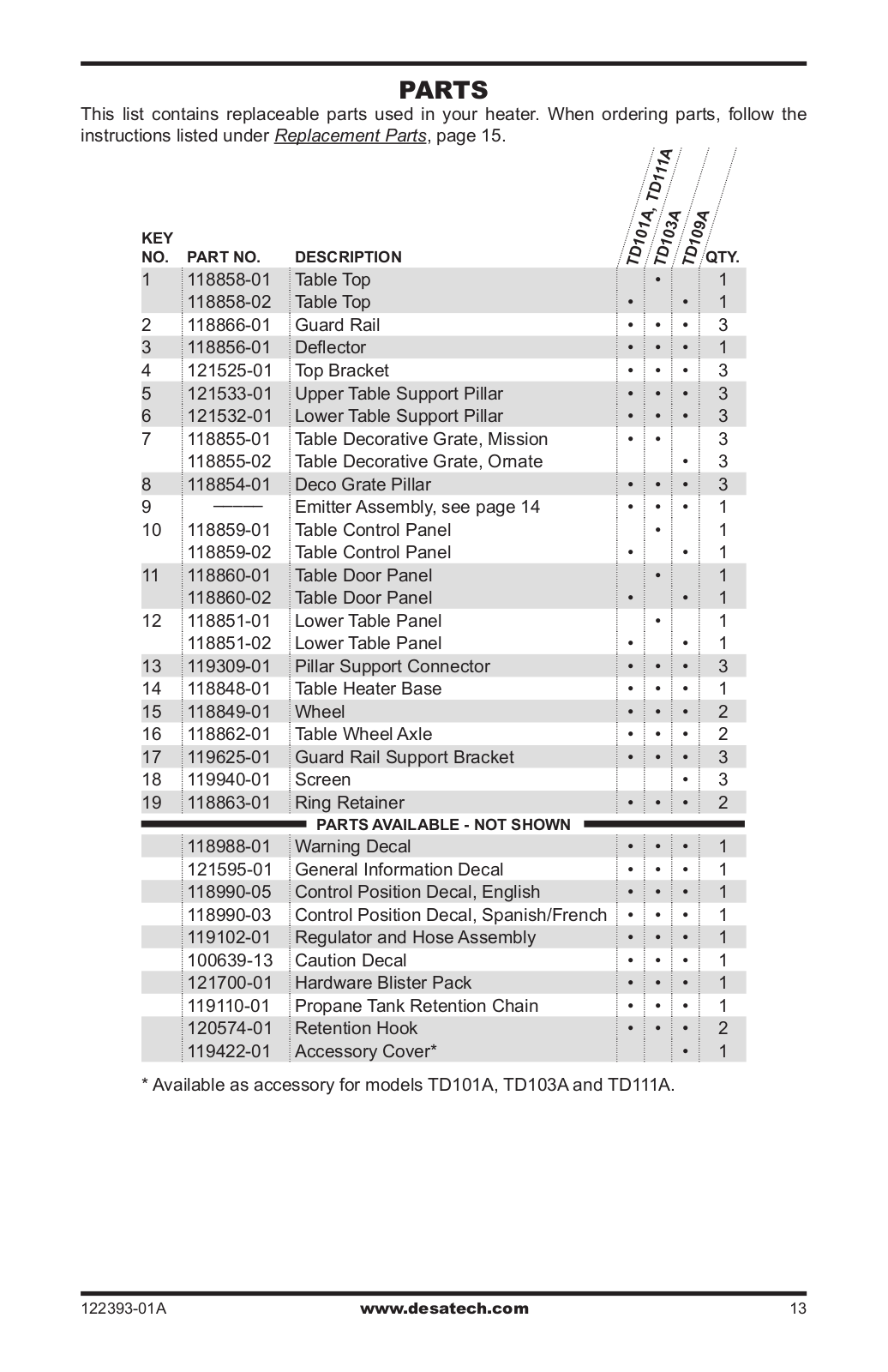
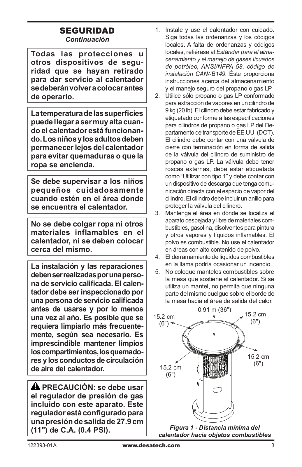
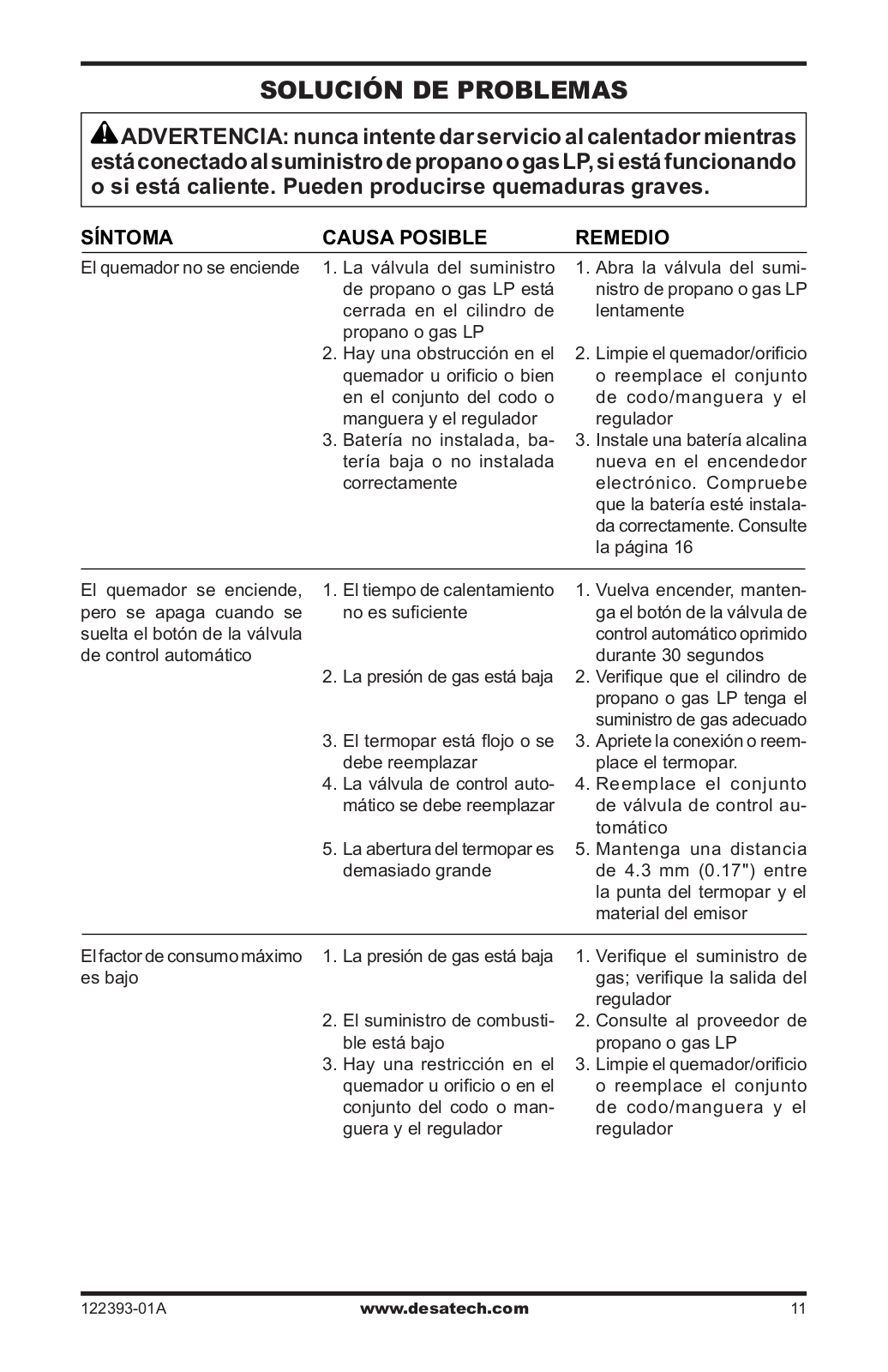
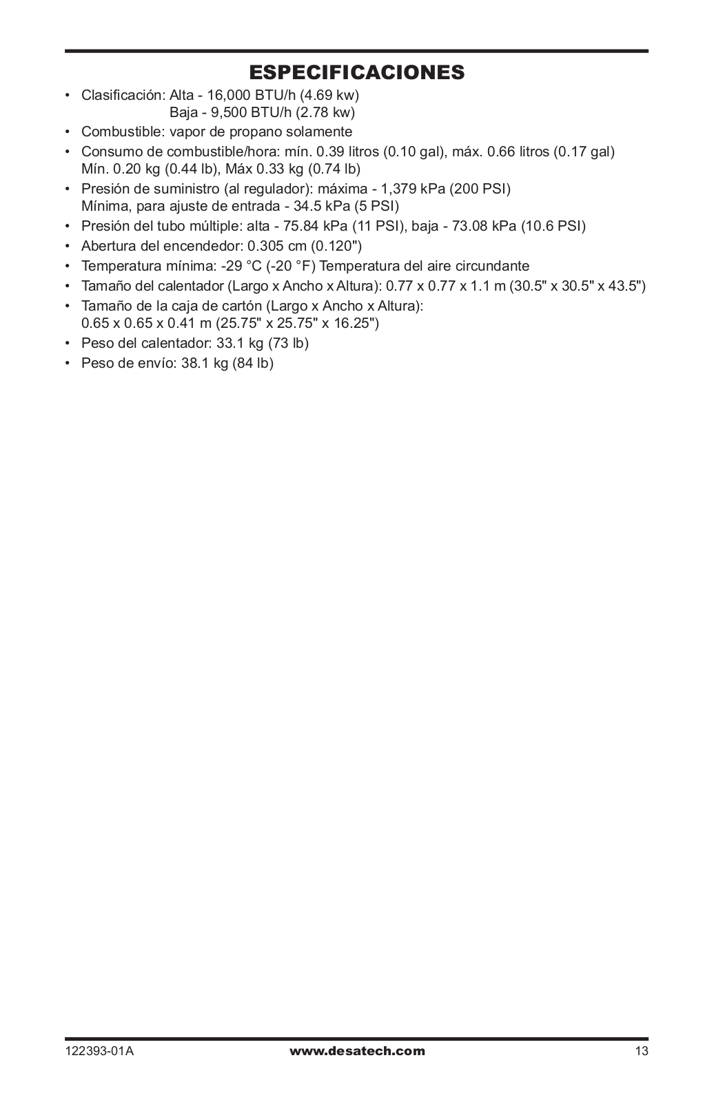
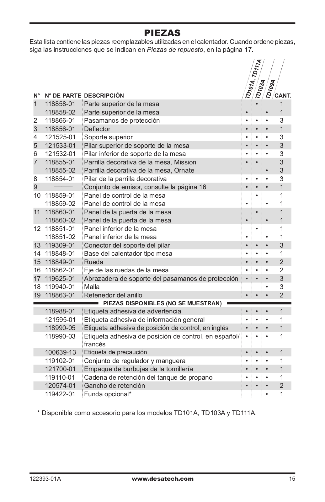
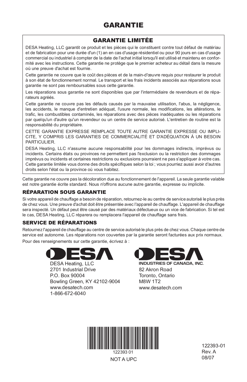
Desa Td101a, Td103a, Td109a, Td111a User Manual
...
Desa User Manual
Download
Specifications and Main Features
Frequently Asked Questions
User Manual
Download
Loading...
+
hidden pages
Unhide
You need points to download manuals.
1 point = 1 manual.
You can buy points or you can get point for every manual you upload.
Buy points
Upload your manuals
 Loading...