


PROPANE/LP GAS LIGHT HEATER
OWNER’S MANUAL
MODELS
TD100A, TD102A,
TD104A AND TD110A
Adjustable Temperature
Settings:
Low - 20,000 Btu
High - 36,500 Btu
WARNING: For
Outdoor Use Only
WARNING: Read and understand this manual before
assembling, starting, or servicing heater. Improper use
of heater can cause serious injury, property damage, or
death. Keep this manual for future reference.
INSTALLER: Leave this manual with the appliance.
CONSUMER: Retain this manual for future reference.
FOR YOUR SAFETY
Donotstoreorusegasolineorotherammablevapors
and liquids in the vicinity of this or any other appliance.
FOR YOUR SAFETY
If you smell gas:
1.
Shut off gas to the appliance.
2. Extinguishanyopename.
3. If odor continues, immedi-
ately call your gas supplier.
For more information, visit www.desatech.com
Fill In For Your Records
Model No. ____________________
(Located on side panel)
Serial No. _____________________
(Located on side panel)
Date of Purchase _______________
Safety .................................................................. 2
TABLE OF CONTENTS
Product Identication ........................................... 4
Unpacking Heater ................................................ 4
Assembly ............................................................. 5
Operation ............................................................. 7
Storage ................................................................ 8
Maintenance ........................................................ 9
Specications ...................................................... 9
SAFETY
WARNING: This product contains and/or generates chemicals
known to the state of California to
cause cancer or birth defects, or
other reproductive harm.
WARNING: Fire, burn, inhalation, and explosion hazard. Keep
solid combustibles, such as
building materials, wood, vinyl
siding, paper or cardboard, a safe
distance away from the heater
as recommended by the instructions. Never use the heater in
spaces which do or may contain
volatile or airborne combustibles,
or products such as gasoline, solvents, paint thinner, dust particles
or unknown chemicals.
WARNING: Improper installation, adjustment, alteration, service or maintenance can cause
injury, property damage, or death.
Read the installation, operating,
and maintenance instructions
thoroughly before installing or
servicing this equipment.
WARNING: For use only outdoors in a well ventilated space.
Do not use heater indoors or in a
building or garage or any unventilated or enclosed areas.
The heater is designed for use as an infrared
patio heater in accordance with the applicable
requirements CSA 5.90 U.S Infrared Patio
Heaters, CAN 1-2.23 Portable Infra Red Heat-
ers for Canada. Other standards govern the
www.desatech.com
Wiring Diagram .................................................... 9
Parts .................................................................. 10
Troubleshooting ................................................. 14
Replacement Parts ............................................ 15
Technical Service............................................... 15
Accessory .......................................................... 15
Warranty ............................................................ 16
use of fuel gases and Heating, LLC for specific
uses. Your local authority can advise you about
these. The primary purpose of outdoor patio
heaters is to provide heating of residential
and nonresidential spaces. Properly used, the
heater provides safe economical heating.
We cannot foresee every use which may be
made of our heaters. CHECK WITH YOUR
LOCAL FIRE SAFETY AUTHORITY IF YOU
HAVE QUESTIONS ABOUT HEATER USE.
Carbon Monoxide Poisoning: Some people
are more affected by carbon monoxide than
others. Early signs of carbon monoxide poi-
soning resemble the flu, with headaches, dizziness and/or nausea. If you have these signs,
the heater may not be working properly. Get
fresh air at once! Have heater serviced.
Propane/LP Gas: Propane/LP gas is odor-
less. An odor-making agent is added to
propane/LP gas. The odor helps you detect
a propane/LP gas leak. However, the odor
added to propane/LP gas may fade. Propane/LP gas may be present even though
no odor exists.
Make certain you read and understand all
warnings. Keep this manual for reference. It
is your guide to safe and proper operation of
this heater.
1. Install and use heater with care. Follow
all local ordinances and codes. In the ab-
sence of local ordinances and codes, refer
to the Standard for Storage and Handling
of Liquefied Petroleum Gas, ANSI/NFPA
58, CSA/-B149 Installation CODE. This
instructs on the safe storage and handling
of propane/LP gases.
2. Use only propane/LP gas set up for vapor
withdrawal in a 20 lb. cylinder. Cylinder
must be constructed and marked in accor-
dance with specifications for propane/LP
cylinders of the U.S. Department of Transportation (DOT) or the National Standard
of Canada CAN/CSA-B339. The cylinder
must be provided with a shutoff valve ter-
minating in a propane/LP supply cylinder
valve outlet. The valve must have external
122527-01B2
SAFETY
Continued
threads and marked “Use with Type 1” and
a safety relief device having a direct communication with the vapor space of the
cylinder. The cylinder used must include
a collar to protect the cylinder valve. The
cylinder must be equipped with a listed
over filling protection device.
3. Keep appliance area clear and free from
combustible materials, gasoline, paint
thinner and other flammable vapors and
liquids. Dust is combustible. Do not use
heater in areas with high dust content.
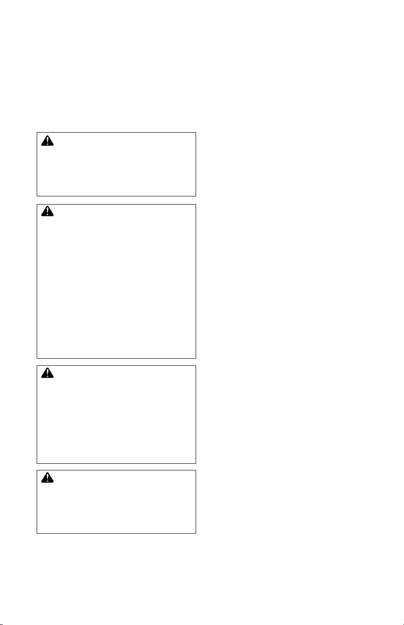
4. Minimum heater clearances from combustibles: Back 4" (10.2 cm), Sides
12" (30.5 cm); Front 42" (1.07 m); Top
16" (40.6 cm) (see Figure 1).
5. Before each use, check heater for leaks.
Never use an open flame to check for a
leak. Apply a mixture of liquid soap and
water to all joints. Bubbles forming show
a leak. Correct all leaks at once.
6. Keep propane/LP cylinder below 100° F
(38° C).
7. Use only the hose and factory preset
regulator provided with the heater. Do not
adjust regulator as gas leaks may occur.
8. Locate hose properly, keeping it out of
pathways where people may trip over it or
in areas where the hose may be subjected
to accidental damage.
9. Check hose before each use of heater.
Disco nnect hose with 9/16 " wrench.
Check for tears and abrasions in hose and
on regulator. If highly worn or cut, replace
with hose specified by manufacturer before using heater.
10. Do not alter heater. Keep heater in its original state. Do not use heater if altered.
11. Locate heater on stable and level surface.
12. Do not operate heater while sleeping or
leave heater unattended.
13. Never move, handle or service a hot
or operating heater. Severe burns may
result. You must wait 20 minutes after
turning heater off.
14. To prevent injury, wear gloves when handling heater.
15. Turn off heater valve and gas supply to
heater when not in use.
16. Use only original replacement parts. This
heater must use design-specific parts.
Do not substitute or use generic parts.
122527-01B 3
www.desatech.com
Improper replacement parts could cause
serious or fatal injuries.
17. Certain materials or items, when stored in
front of heater, will be subjected to radiant
heat and could be seriously damaged.
18. Shut heater off immediately if flashback
occurs (flame inside burner tube). Have
heater serviced.
19. Never attempt to use heater or any
components that have been damaged or
exposed to accidental fire.
20. If you smell gas or suspect a leak, shut
off propane/LP cylinder valve at once.
Ventilate area. Do not strike a match or
create any flame or electric spark. Find
and correct leak before attempting to light
any appliance.
21. Do not block intake air openings.
Any guard or other protective device
removed for servicing must be replaced prior to operating the heater.
Surface temperatures become very
hot when operating heater. Children
and adults should stay away to avoid
burns or clothing ignition.
Young children should be carefully
supervised when they are in the area
of the heater.
16" (40.6 cm)
12"
(30.5 cm)
42"
(1.07 m)
Figure 1 - Clearances from Combustibles
4"
(10.2 cm)
12"
(30.5 cm)

SAFETY
Continued
Clothing or other flammable materials should not be hung from the
heater or placed on or near heater.
Installation and repair should be
done by a qualified service person. Heater should be inspected
before use and at least annually by
a qualified service person. More
frequent cleaning may be required
as necessary. It is imperative that
control compartments, burners, and
circulating air passageways of the
heater be kept clean.
CAUTION: The gas pressure
regulator provided with this
appliance must be used. This
regulator is set for an output
pressure of 28" W.C. (1 P.S.I.).
22. If replacement is required, use only regulator with same setting. See Parts page 13.
23. Use correct pressure specications, see
page 9.
24.
Propane/LP gas cylinder is not provided. Use
a 20 lb. propane/LP gas cylinder marked
propane. The cylinder supply system must
be arranged for vapor withdrawal. The cylinder used must include a collar to protect
the cylinder valve. The cylinder must be
provided with a shutoff valve terminating in a
propane/LP gas supply cylinder valve outlet
specified, as applicable, for connection no.
600 in the Compressed Gas Association’s
Limited Standard Cylinder Valve Outlet Connection for Propane Small Valve Series.
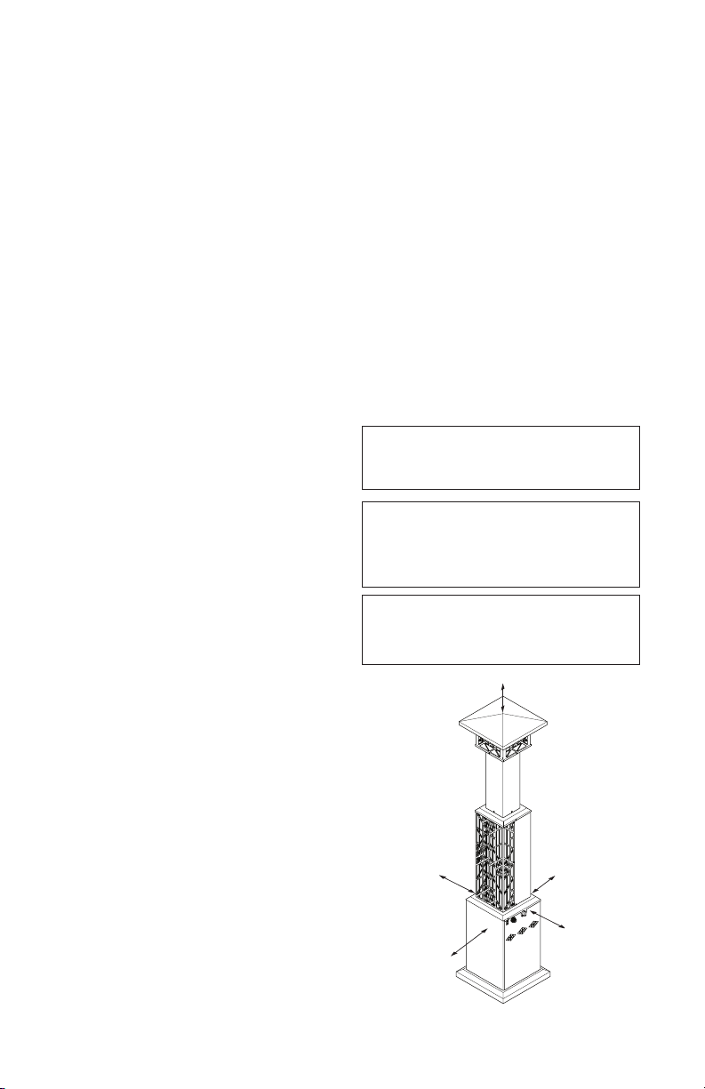
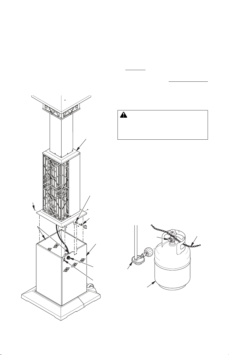
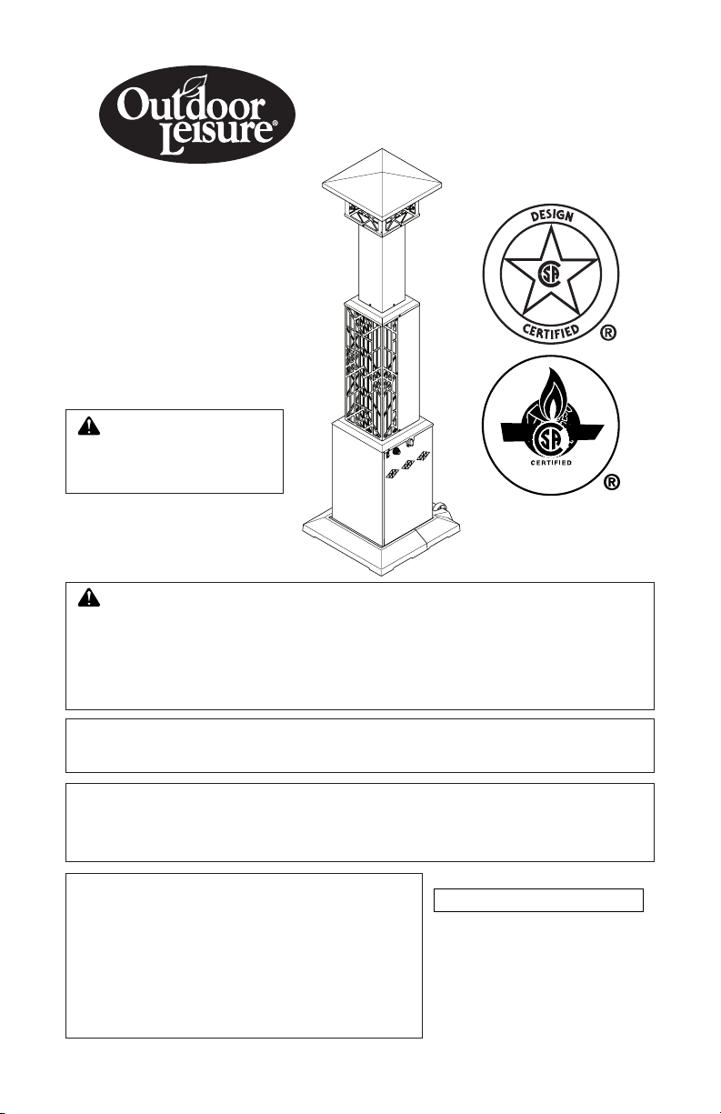
PRODUCT
IDENTIFICATION
Gas Light
(Inside Deco
Shroud)
Burner
(Behind Grill)
Control
Knob
On/Off
Switch
Figure 2 - Outdoor Patio Heater with Light
Electronic
Ignitor
Cabinet
Base
Assembly
UNPACKING HEATER
Check all items for shipping damage. If heater
is damaged, promptly inform dealer where you
bought heater.
1. Remove first base half from box.
2. Remove top cap, 2 deco light shrouds,
top and packaging materials from box.
Set parts aside in a safe location.
3. Remove burner assembly from box, leaving packaging materials on bottom of assembly. Set aside in the upright position.
4. Remove lightpost pieces, cabinet base
and tank door from box. Set aside.
www.desatech.com
5. Remove 6 screws securing grill to burner
assembly. Remove second base half from
inside burner assembly. Reattach grill to
burner assembly.
You should have the following assembly parts:
Top Cap (1), Burner Assembly (1), Cabinet
Base (1), Front Base (1), Rear Base (1), Wheel
(2), Base Cabinet Door (1), Lightpost Panel
(4), Deco Light Shroud (2), Upper Screen (4),
Lightpost Top (1), Propane Tank Retention
Chain (1), Retention Hook (2), Hardware Pack-
age (1) (see pages 10 thru 13).
122527-01B4
ASSEMBLY
F
H
B
C
D
E
G
A
Estimated assembly time: 45 minutes
Tools required:
• #2 Phillips screwdriver
• 1/2", 5/16" and 7/32" Open end wrenches
Hardware packet provided with heater may
contain more parts than needed for heater
assembly.
Hardware packet contains the following items
shown on pages 10 through 13:
Electronic Ignitor (1), Ignitor Wire (1), Ground
Wire (1), Valve Knob (1), Propane Tank Retention Chain (1), Retention Hook (2), D Batteries (2)
and AA Battery (1).
Parts are referenced by designated letter
throughout assembly instructions. Hardware
packet contains the following (quantity used
in parenthesis):
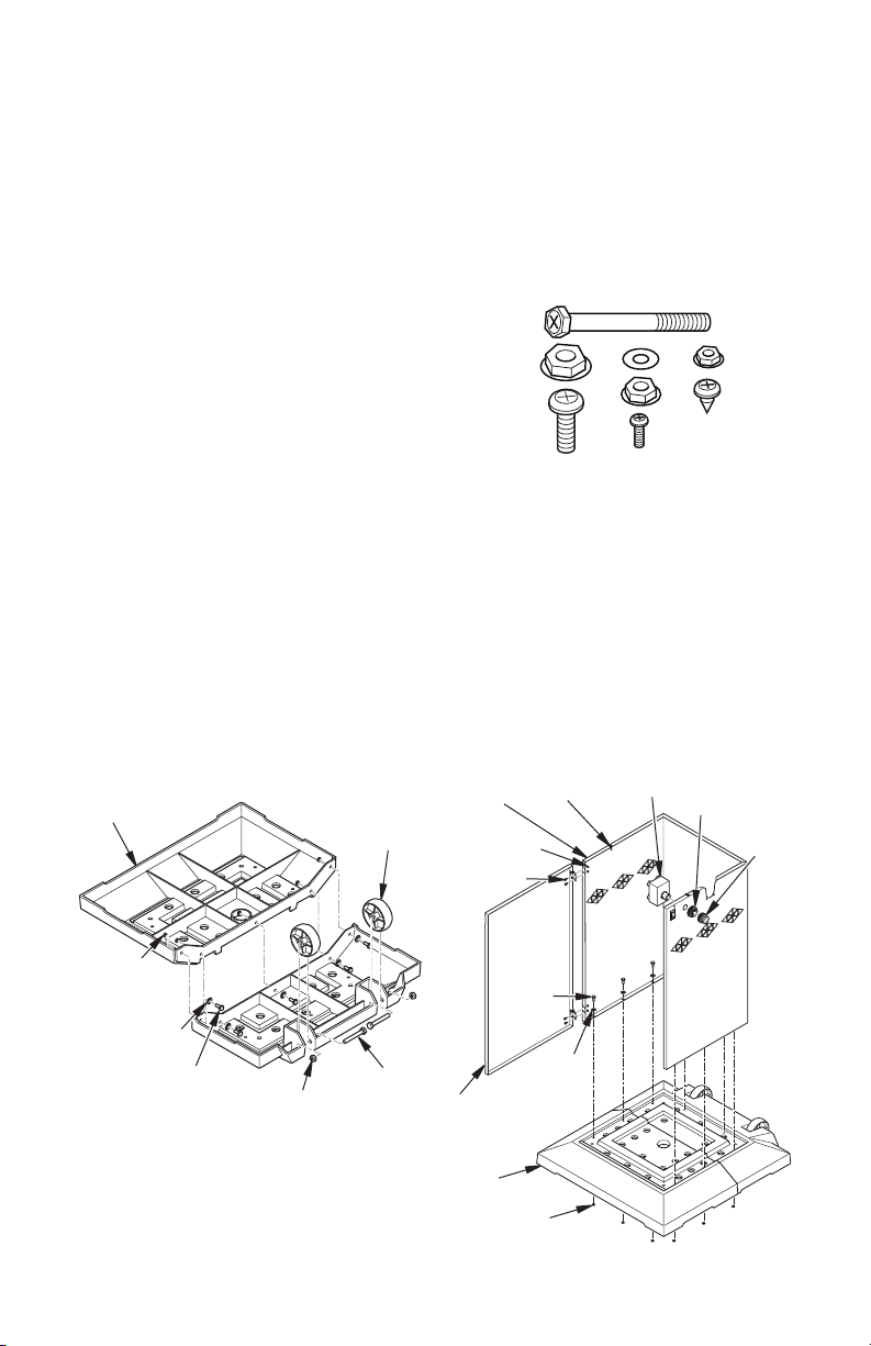
Description Part No.
A 2 1/4" Hex Bolt (2) HC4-18C
B 12 mm Hex Nut (2) NPC-5C
C 5/8" Screw (14) 119619-03
D 5 mm Washer (14) 119600-02
E 5/16" Hex Nut (14) NPC-3C
F 3/8" Screw (20) 119619-06
G 7/32" Hex Nut (20) NPC-1C
H 3/8" Self tapping screw (34) 119620-02
BASE ASSEMBLY
1. Connect 2 base parts using 5 screws (C),
5 washers (D) and 5 nuts (E) as shown in
Figure 3.
2. Turn base upside down. Attach 2 wheels,
2 hex bolts (A) and 2 nuts (B) as shown
in Figure 3. Do not overtighten.
3. Being careful not to scratch paint, lay
cabinet base onto back side (use foam
packaging block to support rear top of
cabinet base). Align holes in bottom
edges of cabinet base with holes in base
as shown in Figure 4. Attach with 1 screw
Base
Wheel
Nut (E)
Washer (D)
Screw (C)
Nut (B)
Figure 3 - Attaching Wheels to Base
Hex Bolt (A)
(C), 1 washer (D) and 1 nut (E) for each of
the 9 holes (see Figure 4). Set assembly
upright.
4. Install chain retainers (“S” hooks) to upper edges of cabinet base as shown in
Figure 4.
5. Install electronic ignitor through cabinet
wall as shown in Figure 4. Hand tighten.
6. Attach tank door to cabinet with 4 screws
(F) and 4 nuts (G) as shown in Figure 4.
Set entire assembly aside.
Cabinet
Base
Nut (G)
Screw (F)
Screw
Tank
Door
Chain
Retainer
(C)
Washer
(D)
Ignitor
Retainer
Ring
Ignitor
Cap
Base
122527-01B 5
www.desatech.com
Nut (E)
Figure 4 - Cabinet Base Assembly
ASSEMBLY
Continued
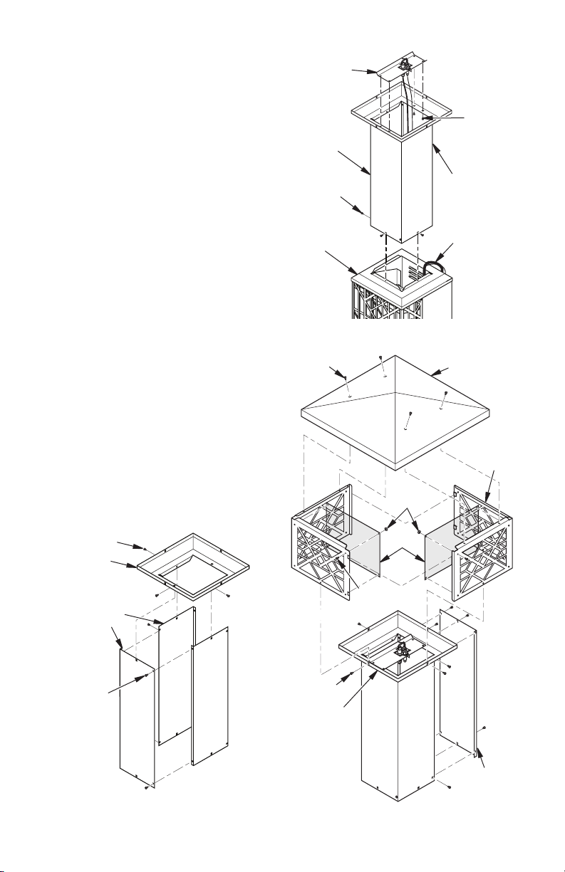
BURNER AND LIGHTPOST ASSEMBLY
1. Locate 4 lightpost panels that are packaged together. Assemble 3 of the pieces
with 4 screws (H) as shown in Figure 5.
2. Place lightpost top over panel assembly
aligning screw holes. Attach with 3 screws
(H) as shown in Figure 5.
3. Pilot light and wiring has been placed
inside top of burner assembly for shipping. Carefully remove pilot from inside
assembly and let wiring and pilot hang
down back of assembly.
4. Place pilot assembly on top of lightpost
top as shown in Figure 6. Attach with
4 screws (H). Check wire connections
before proceeding.
5. Place lightpost panels and top assembly
on top of burner assembly aligning back
side of each assembly. See Figure 6. Attach with 3 screws (H).
6. Attach 4 light shroud screens to light
shrouds with 4 screws (F) and 4 nuts (G)
each as shown in Figure 7. Only 2 of the
4 screens are shown.
7. Place deco light shrouds on top of light-
post top (see Figure 7). Make sure flanges
are on top. Slide shroud tabs together.
Attach to lightpost top with 4 screws (H)
through holes in bottom of shroud pieces
(see Figure 7). Tighten all screws.
8. Attach lightpost top cap to shroud assembly
with 4 screws (H) as shown in Figure 7.
Screw (H)
Lightpost
Top
Lightpost
Panels
Pilot
Assembly
Lightpost
Assembly
Screw (H)
Burner
Assembly
Figure 6 - Connecting Lightpost and
Burner Assembly
Screw (H)
Nut (G)
Screen
Screw (F)
Open Side
of Panel
Assembly
to Back of
Heater
Pilot Light
Wiring to
Back of
Heater
Lightpost
Top Cap
Screw
(H)
Deco
Light
Shroud
Screw (H)
Figure 5 - Lightpost Panels and Top
Assembly
Screw (H)
Lightpost
Top
Figure 7 - Attaching Pilot and Shroud
www.desatech.com
Fourth
Lightpost
Panel
122527-01B6
ASSEMBLY
Continued
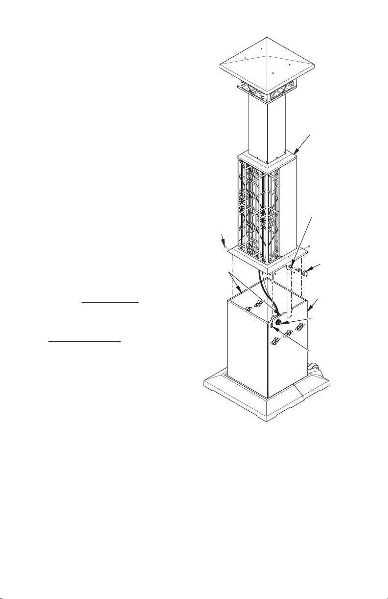
HEATER ASSEMBLY
Note: If needed, acquire assistance lifting
assembly.
1. Place entire lightpost assembly on top
of cabinet base assembly. Attach with 4
screws (H) as shown in Figure 8. Install
2 screws (H) into holes on each side of
control valve. Attach control valve nut and
control knob to control valve.
2. Connect 2 brown wires to ON/OFF switch.
Lightpost/
Burner
Assembly
Control
Screw (H)
Chain
Retainer
Valve
Control
Valve Nut
and Control
Knob
Cabinet
Assembly
3. Connect white ground wire attached to
cabinet to right post on electronic ignitor.
Remove wire tie. Connect black ignitor
wire to left post on electronic ignitor. Install
battery in ignitor as shown on page 12.
4. Install batteries in battery holder as shown
on page 12. Do not mix batteries.
5. Connect regulator to gas cylinder, see
Operation. Gas cylinder will sit inside of
cabinet assembly.
6. Check for leaks. See Checking for Leaks
page 8.
7.
Attach fourth lightpost panel to assembly with
6 screws (H) as shown in Figure 7, page 6.
OPERATION
CAUTION: Do not stand in
front of heater while lighting.
Stand at the side when lighting
the heater.
Use only a 20 lb. propane/LP cylinder (not
included). See safety information for proper
cylinder selection. Connect the hose/regulator assembly to the cylinder (see Figure 9).
The hose should already be connected to the
heater. Connect hose to the valve inlet (see
Figure 9). Tighten rmly using a wrench.
Route retention chain through at least one
of the handles of the propane/LP tank (see
Figure 9). Make sure to route chain through
handle on tank and NOT around tank valve.
Chain must not interfere with valve. Attach
hooks on both ends of chains to chain retain-
ers installed on cabinet base (see Figure 8).
Retention
Valve
Inlet
Chain
Ignitor
ON/OFF
Switch
Figure 8 - Attaching Lightpost/Burner
Assembly to Cabinet Assembly
122527-01B 7
www.desatech.com
Hose/Regulator
Assembly
20 lb.
Propane/LP
Cylinder
Figure 9 - Connecting Hose/Regulator
Assembly to Propane/LP Cylinder
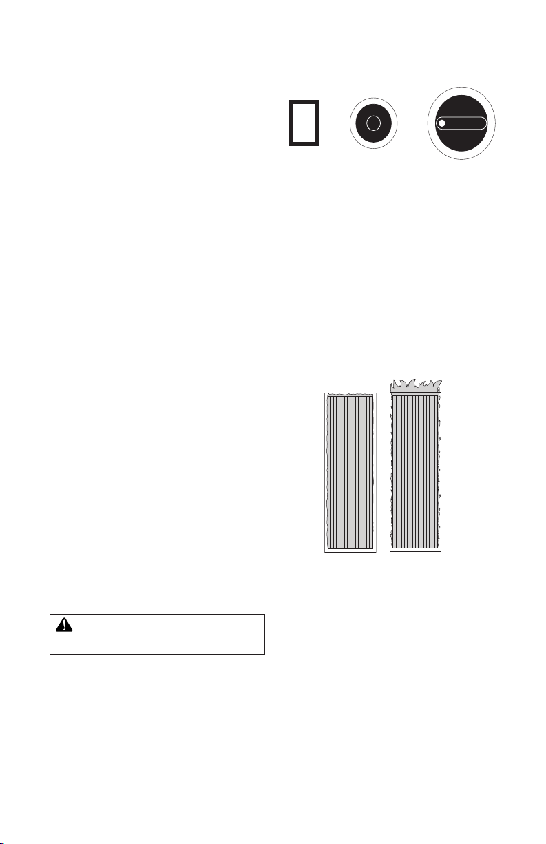
OPERATION
IG NI TO R
GA S LI GH T
PO WE R SW IT CH
OF F
STA RT-L OW
HI GH
ON
OFF
Continued
CHECKING FOR LEAKS
1. Turn heater valve to OFF position.
2. Turn cylinder supply valve fully counter
clockwise to OPEN position.
3. Use a noncorrosive leak detection solution
to check the connection for leaks before
attempting to light heater. If leak is found,
turn cylinder valve to CLOSE and do not
use until all leaks are corrected.
LIGHTING INSTRUCTIONS
Gas Light
1. Press power switch to ON, gas light will
automatically light.
2. Press power switch to OFF to turn gas
light off.
3. To turn off gas supply to gas light, turn
knob on manual shutoff valve to OFF.
Manual shutoff valve is located on gas
train assembly inside of heater cabinet.
Note: Be sure manual shutoff valve is in the
ON position to operate gas light.
Main Burner
1. Push heater control knob in and turn coun-
ter clockwise to the START position.
2. Push control knob in and press ignitor
button. Repeat until heater is lit.
3. Continue holding knob in for approximately 30 seconds. Heater should remain
lit in the LOW heat setting.
4. For more heat, press knob and rotate
counterclockwise to HIGH setting.
5. If RELIGHTING, wait 5 minutes for heater
to cool and gas to clear, then follow steps
1 through 3.
Figure 10 - Gas Light Heater Controls
SHUTDOWN INSTRUCTIONS
1. Press control knob and rotate clockwise
to OFF position.
2. Close propane/LP cylinder valve (rotate
knob clockwise).
BURNER OPERATION
Visually inspect burner for proper operation.
The burner should glow red with a minimum
amount of flame lap after initial ring. If flame
lap on burner is excessive, have heater ser-
viced. Pressure may be too high or nozzle/
burner may be damaged.
Correct
Flame
Pattern
Figure 11 - Burner Operation
Incorrect
Flame
Pattern
STORAGE
CAUTION: Disconnect heater
from propane/LP supply cylinder.
1. Do not store heater while attached to
propane/LP cylinder. Close cylinder valve.
Remove the hose/regulator assembly
from the propane/LP cylinder by turning
the fuel gas connector nut clockwise.
2. Storage of heater inside is permissible
only if the cylinder is disconnected and
removed from the appliance.
www.desatech.com
3. Store propane/LP cylinder in safe manner.
Refer to Chapter 5 of Standard for Storage
and Handling of Liqueed Petroleum Gases,
ANSI/NFPA 58. Follow all local codes.
Cylinders must be stored outdoors in a
well-ventilated area out of reach of children.
Disconnected cylinders must have threaded
valve plugs tightly installed, and must not
be stored in a building, garage or any
other enclosed area. Never store cylinders
near high heat, open flame, or where
temperatures exceed 100° F (38° C).
4. Store in a dry, clean, and safe place.
122527-01B8
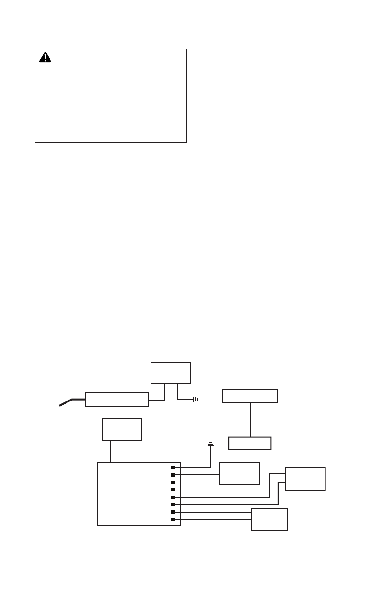
MAINTENANCE
Gas Light
Burner
Ground
Control Module
Battery
Holder
Black
Orange
Brown
Brown
Brown
White
WhiteWhite
Brown
Red
Black
I S
Electronic
Ignitor
Ignitor Electrode
Ground
ON/OFF
Switch
Control
Valve
Thermocouple
Gas Valve
WARNING: Never attempt
to service heater while it is
connected to propane/LP supply,
operating, or hot. Severe burns
can occur. Any guard or other
protective device removed for
servicing must be replaced prior
to operating the heater.
1. Keep heater clean. Remove any debris
from ventilation openings.
2. Inspect heater before each use. Check
connections for leaks. Apply mixture of
liquid soap and water to connections.
Bubbles forming show a leak that must
be corrected. Correct all leaks at once.
3. Inspect hose/regulator assembly before
each use. If hose is highly worn or cut,
replace it immediately. At least annually,
remove hose/regulator assembly from
heater to inspect entire length of hose.
Replacement hose must be same type
as supplied with unit.
4. Spiders and insects can create a dangerous condition that may damage heater or
make it unsafe. Keep burner area clean
of all spiders, webs, or insects.
5. Have heater inspected yearly by a quali-
ed service person.
WIRING DIAGRAM
SPECIFICATIONS
• Rating: High - 36,500 Btu/Hr (10.7 kw)
Low - 20,000 Btu/Hr (5.86 kw)
• Fuel: Propane Vapor Only
• Fuel Consumption/Hour: Min. 0.22 gal
(0.83 liter), Max. 0.39 gal (1.48 liter)
Min. 0.93 lb (0.42 kg), Max 1.67 lb (0.76 kg)
• Supply Pressure (To Regulator):
Maximum - 200 psi (1,379 Kpa)
Minimum, for input adjustment - 5 psi
(34.5 Kpa)
• Manifold Pressure: High - 1 psi (6.89 kPa),
Low - 0.98 psi (6.77 kPa)
• Ignitor Gap: 0.120"
• Mi ni mu m Tempe ra tu re: - 20°F (29 °C)
Surrounding Air Temperature
• Heater Size (L x W x H):
18" x 17.125" x 82" (0.45 x 0.43 x 2.1 m)
• Carton Size (L x W x H):
38.625" x 18.125" x 18" (0.98 x 0.46 x 0.45 m)
• Heater Weight: 68 lb (30.8 kg)
• Shipping Weight: 82 lb (37.2 kg)
122527-01B 9
www.desatech.com
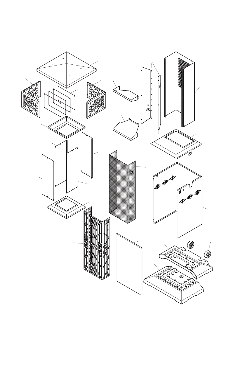
PARTS
5
17
14
12
11
8
10
1
2
18
7
9
6
2
3
4
4
4
4
13
16
15
CABINET ASSEMBLY
MODELS TD100A, TD102A, TD104A AND TD110A
www.desatech.com
122527-01B10
PARTS
CABINET ASSEMBLY
This list contains replaceable parts used in your heater. When ordering parts, follow the
instructions listed under Replacement Parts, page 15.
KEY
NO. PART NO. DESCRIPTION QTY.
1 118890-01 Lightpost Top Cap • 1
118890-02 Lightpost Top Cap • • 1
2 118891-01 Deco Light Shroud Assembly, Mission • • 2
118891-02 Deco Light Shroud Assembly, Ornate • 2
3 118892-01 Lightpost Top • 1
118892-02 Lightpost Top • • 1
4 118885-01 Lightpost Panel • 4
118885-02 Lightpost Panel • • 4
5 118884-01 Lower Burner Housing Top • 1
118884-02 Lower Burner Housing Top • • 1
6 118887-01 Reflector Right/Left • • • 2
7 118888-01 Reflector Top • • • 1
8 118889-01 Reflector Bottom • • • 1
9 118883-01 Lower Burner Housing • 1
118883-02 Lower Burner Housing • • 1
10 118882-01 Cabinet Base Top • 1
118882-02 Cabinet Base Top • • 1
11 119004-01 Lower Screen • • • 1
12 118900-01 Front Lower Burner Grate, Mission • • 1
118900-02 Front Lower Burner Grate, Ornate • 1
13 118905-01 Base Cabinet Door • 1
118905-02 Base Cabinet Door • • 1
14 118881-01 Cabinet Base • 1
118881-02 Cabinet Base • • 1
15 121566-01 Lightpost Front Base • • • 1
16 121565-01 Lightpost Rear Base • • • 1
17 118849-01 Wheel • • • 2
18 119005-01 Upper Screen • • • 4
* 119423-01 Accessory Cover (not shown) • 1
* Available as accessory for models TD100A, TD102A and TD110A.
TD100A, TD110A
TD102A
TD104A
122527-01B 11
www.desatech.com
1
2
2
6
19
17
14
13
12
16
15
18
11
20
22
10
5
7
8
9
3
21
4
AA
Battery
Positive
UP
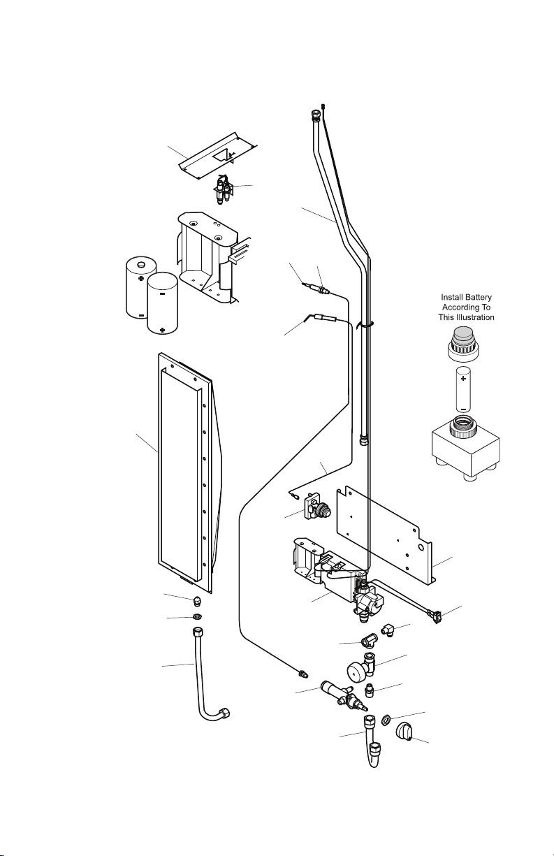
PARTS
GAS COMPONENTS
MODELS TD100A, TD102A, TD104A AND TD110A
CAUTION: Do not disposed of
in re. Batteries may explode or
leak, and cause burn or injury.
Do not mix old
and new batteries.
Do not mix
alkaline, standard
(carbon - zinc)
or rechargeable
(nickel - cadmium)
batteries.
D Batteries
www.desatech.com
122527-01B12
PARTS
GAS COMPONENTS
MODELS TD100A, TD102A, TD104A AND TD110A
This list contains replaceable parts used in your heater. When ordering parts, follow the
instructions listed under Replacement Parts, page 15.
KEY
NO. PART NO. DESCRIPTION QTY.
1 118893-01 Light Post Burner Bracket 1
2 120373-01 Top Light Burner Assembly 1
3 118904-01 Lightpost Burner Flex Line 1
4 120570-01 Ignitor Electrode Kit 1
5 121594-02 Thermocouple 1
6 119091-01 Lightpost Main Burner 1
7 118911-01 Main Burner Orice 1
8 NJF-8C Orice Nut 1
9 118913-01 Main Burner Tube 1
10 098271-11 Radiant Ignitor Wire 1
11 118868-02 Main Burner Control Valve 1
12 119292-01 Manual Shutoff Valve 1
13 118914-01 Valve Flex Line 1
14 099393-02 Valve Knob 1
15 098508-01 Control Nut 1
16 119293-01 Outlet Fitting 1
17 118907-01 Outlet T Fitting 1
18 111435-01 Electronic Ignitor 1
19 118909-01 Outlet Elbow 1
20 118896-01 Lightpost Component Plate 1
21 100898-01 Thermocouple Nut 2
22 101886-01 Fan Switch 1
121700-02 Hardware Blister Pack 1
119093-01 Regulator and Hose Assembly 1
120578-01 Magnetic Door Catch 2
119110-01 Propane Tank Retention Chain 1
120574-01 Retention Hook 2
118990-02 Control Position Decal, English 1
118990-03 Control Position Decal, Spanish/French 1
118990-04 Control Position Decal, Eng/Spn/Frn 1
118988-02 Warning Decal 1
121595-04 Model Data Decal 1
100639-13 Caution Decal 1
119297-01 Regulator Label 1
PARTS AVAILABLE - NOT SHOWN
122527-01B 13
www.desatech.com
TROUBLESHOOTING
WARNING: Never attempt to service heater while it is connected
to propane/LP supply, operating, or hot. Severe burns can occur.
SYMPTOM
Burner fails to light
Burner lights but goes out
when automatic control valve
button is released
Maximum burn rate is low
POSSIBLE CAUSE
1. Propane/LP supply valve
closed on propane/LP cyl-
inder
2. Blockage in burner/orice
elbow/hose and regulator
assembly
3. Battery not installed, battery
power low or battery not
installed correctly
1. Not enough warm-up time
2. Low gas pressure
3. Th ermocouple loo se or
needs to be replaced
4. Automatic control valve
needs to be replaced
5. Thermocouple gap is too
great
1. Low gas pressure
2. Low fuel supply
3. Restriction in burner/orice
elbow/hose and regulator
assembly
REMEDY
1. Open propane/LP supply
valve slowly
2. Clean burner/replace orice
elbow/hose and regulator
assembly
3. Install new alkaline battery
in electronic ignitor. Verify
battery is installed correctly.
See page 12
1. Re li ght, hold a utomatic
control valve button in 30
seconds
2. Check propane/LP cylinder
for proper gas supply
3. Tighten connection or replace thermocouple
4. Replace automatic control
valve assembly
5. Maintain 0.20" gap between
tip of thermocouple and
emitter material
1. Check gas supply; check
regulator output
2. Consult propane/LP gas
supplier
3. Clean burner/replace orice
elbow/hose and regulator
assembly
www.desatech.com
122527-01B14

REPLACEMENT PARTS
Note: Use only original replacement parts.
This will protect your warranty coverage for
parts replaced under warranty.
PARTS UNDER WARRANTY
Contact authorized dealers of this product. If
they can’t supply original replacement part(s),
call DESA Heating, LLC at 1-866-672-6040.
When calling DESA Heating, LLC, have
ready:
• your name
• your address
• model and serial numbers of your heater
• how heater was malfunctioning
• purchase date
TECHNICAL SERVICE
You may have further questions about installation, operation, or troubleshooting. If so, contact DESA Heating, LLC at 1-866-672-6040.
When calling please have your model and
serial numbers of your heater ready.
ACCESSORY
Purchase accessories and parts from your
local dealer. If they can not supply these accessories call DESA Heating, LLC (US) at
1-866-672-6040 or DESA Industries (CAN)
at 1-415-255-5677 for information. You can
also write to the address listed on the back
page of this manual.
Usually, we will ask you to return the part to
the factory.
PARTS NOT UNDER WARRANTY
Contact authorized dealers of this product.
If they can’t supply original replacement
part(s), call DESA Heating, LLC (US) at
1-866-672-6040 or DESA Industries (CAN) at
1-415-255-5677 for referral information. A list
of authorized dealers can be found by visiting
www.desatech.com.
When calling DESA Heating, LLC, have
ready:
• model and serial numbers of your heater
• the replacement part number
You can also visit DESA Heating, LLC’s web
site at www.desatech.com.
PATIO HEATER COVER - 119423-01
A heater cover accessory may be purchased
to protect your patio heater. Made of black
polyester material with Outdoor Leisure
logo.
Patio heater cover accessory may be ordered
through this website:
www.aboutoutdoorleisure.com
Click “Online Outlet”.
Click “Patio Heaters”.
Click “Accessories”.
122527-01B 15
www.desatech.com
WARRANTY
LIMITED WARRANTY
DESA Heating, LLC warrants this product and any parts thereof, to be free from defects in materials and
workmanship for one (1) year for residential home owner usage or 90 days for commercial/industrial
usage from the date of first purchase when operated and maintained in accordance with instructions.
This warranty is extended only to the original retail purchaser, when proof of purchase is provided.
This warranty covers only the cost of parts and labor required to restore the product to proper operating
condition. Transportation and incidental costs associated with warranty repairs are not reimbursable
under this warranty.
Warranty service is available only through authorized dealers and service centers.
This warranty does not cover defects resulting from misuse, abuse, negligence, accidents, lack of proper
maintenance, normal wear, alteration, modification, tampering, contaminated fuels, repair using improper
parts, or repair by anyone other than an authorized dealer or service center. Routine maintenance is
the responsibility of the owner.
THIS EXPRESS WARRANTY IS GIVEN IN LIEU OF ANY OTHER WARRANTY EITHER EXPRESSED
OR IMPLIED, INCLUDING WARRANTIES OF MERCHANTABILITY AND FITNESS FOR A PARTICULAR PURPOSE.
DESA Heating, LLC assumes no responsibility for indirect, incidental or consequential damages. Some
states do not allow the exclusion or limitation of incidental or consequential damages or limitations or
exclusions may not apply to you. This Limited Warranty gives you specific legal rights and you may
also have other rights which vary from state to state.
This warranty does not cover discoloration due to operation of heater. The only warranty applicable is our
standard written warranty. We make no other warranty, expressed or implied.
WARRANTY SERVICE
Should your heater require service, return it to your nearest authorized service center. Proof of purchase
must be presented with the heater. The heater will be inspected. A defect may be caused by faulty materials
or workmanship. If so, DESA Heating, LLC will repair or replace the heater without charge.
REPAIR SERVICE
Return the heater to your nearest authorized service center. Each Service Center is independently owned
and operated. Repairs not covered by the warranty will be billed at standard prices.
For information about this warranty write:
DESA Heating, LLC
2701 Industrial Drive
P.O. Box 90004
Bowling Green, KY 42102-9004
1-866-672-6040
www.desatech.com
82 Akron Road
Toronto, Ontario
M8W 1T2
416-255-5333
122527-01
Rev. B
11/07
CALENTADOR DE LÁMPARA DE
PROPANO O GAS LP
MANUAL DEL PROPIETARIO
MODELOS
TD100A, TD102A,
TD104A y TD110A
Configuración ajustable
de la temperatura:
Baja: 20,000 BTU
Alta: 36,500 BTU
ADVERTENCIA:
para uso en exteriores solamente
ADVERTENCIA: lea y comprenda este manual antes de
ensamblar, arrancar o dar servicio al calentador. El uso inadecuado del calentador puede ocasionar lesiones graves,
daños a la propiedad o la muerte. Conserve este manual
para referencias futuras.
INSTALADOR: deje este manual junto con el aparato.
CONSUMIDOR: conserve este manual para futuras referencias.
POR SU SEGURIDAD
No guarde ni utilice gasolina u otros vapores y líquidos
inamables cerca de este aparato ni de cualquier otro.
POR SU SEGURIDAD
Llénelo para sus expedientes
Si percibe olor a gas:
1. Cierre el suministro de gas al aparato.
2.
Apague cualquier llama al descubierto.
3. Si el olor continúa, llame inmediatamente a su proveedor de gas.
Para obtener más información, visite www.desatech.com
N° de modelo ______________
(Situado en el panel lateral)
N° de serie _________________
(Situado en el panel lateral)
Fecha de compra ____________

Seguridad ............................................................ 2
TABLA DE CONTENIDO
Identicación del producto ................................... 5
Desempaque del calentador................................ 5
Ensamble............................................................. 5
Funcionamiento ................................................... 9
Almacenamiento ................................................ 10
Mantenimiento ....................................................11
Especicaciones .................................................11
SEGURIDAD
ADVERTENCIA: este produc-
to contiene y/o genera químicos
que el estado de California
reconoce que causan cáncer,
defectos de nacimiento u otros
daños relacionados con la reproducción.
ADVERTENCIA: peligro de
incendio, quemaduras, inhalación y explosión. Mantenga los
combustibles sólidos, como
materiales de construcción, madera, revestimientos de vinilo,
papel o cartón a una distancia
segura del calentador, como se
recomienda en las instrucciones. Nunca use el calentador en
áreas en las que haya o pueda
haber combustibles volátiles o
que se acumulen en el aire, o
productos como gasolina, solventes, disolvente de pintura,
partículas de polvo o químicos
desconocidos.
ADVERTENCIA: si la instala-
ción, el ajuste, las alteraciones,
el servicio o el mantenimiento no
se realizan correctamente, se podrían ocasionar lesiones, daños
a la propiedad o la muerte. Lea
cuidadosamente las instrucciones de instalación, operación y
mantenimiento antes de instalar
el equipo o de darle servicio.
www.desatech.com
Diagrama de cableado ...................................... 12
Solución de problemas ...................................... 13
Piezas ................................................................ 14
Piezas de repuesto ............................................ 18
Servicio técnico ................................................. 19
Accesorios ......................................................... 19
Garantía............................................................. 20
ADVERTENCIA: para usarse
en exteriores solamente, en un
área bien ventilada. No utilice el
calentador en interiores ni en un
edicio, garaje o cualquier otra
área cerrada o sin ventilación.
El calentador está diseñado para utilizarse
como un calentador infrarrojo para patios, de
acuerdo con los requisitos aplicables de CSA
5.90 para calentadores infrarrojos para patios
de EE.UU. y CAN 1-2.23 para calentadores
infrarrojos para Canadá. Otros estándares rigen
el uso de gases combustibles y productos de
calefacción para usos específicos. Las autoridades locales pueden informarle acerca de éstos.
El objetivo principal de los calentadores para
patios en exteriores es proporcionar calefacción
a espacios residenciales y no residenciales.
Cuando se usa correctamente, el calentador
proporciona calefacción económica y segura.
No podemos prever todos los usos que se les
pueden dar a nuestros calentadores. CON-
SULTE A LAS AUTORIDADES LOCALES
DE SEGURIDAD CONTRA INCENDIOS SI
TIENE ALGUNA PREGUNTA ACERCA DEL
USO DE CALENTADORES.
Intoxicación con monóxido de carbono: el
monóxido de carbono afecta más a algunas
personas que a otras. Los primeros signos de
intoxicación con monóxido de carbono son
semejantes a los de la gripe, con dolor de
cabeza, mareo o náusea. Si usted presenta
estos síntomas, es posible que el calentador
no esté funcionando correctamente. ¡Respire
aire fresco inmediatamente! Haga que se
le dé servicio al calentador.
Propano o gas LP: el propano o gas LP es
inodoro. Al propano o gas LP se le agrega
un agente que tiene olor. El olor le ayuda
detectar las fugas de propano o gas LP. Sin
embargo, el olor que se añade al propano o
gas LP se puede desvanecer. Es posible que
haya propano o gas LP en el entorno aunque
no haya ningún olor.
122527-01B2

SEGURIDAD
Continuación
Asegúrese de leer y comprender todas las
advertencias. Conserve este manual como
referencia. Es su guía para la operación segura y correcta de este calentador.
1. Instale y use el calentador con cuidado.
Siga todas las ordenanzas y los códigos
locales. A falta de ordenanzas y códigos
locales, refiérase al Estándar para el
almacenamiento y el manejo de gases
licuados de petróleo, ANSI/NFPA 58,
código de instalación CSA/-B149. Éste
proporciona instrucciones acerca del
almacenamiento y el manejo seguro del
propano o gas LP.
2. Utilice sólo propano o gas LP conformado
para extracción de vapores en un cilindro de
9 kg (20 lb). El cilindro debe estar fabricado
y etiquetado conforme a las especificaciones para cilindros de propano o gas LP del
Departamento de transporte de EE.UU.
(DOT) o conforme al Estándar nacional
de Canadá CAN/CSA-B339. El cilindro
debe contar con una válvula de cierre con
terminación en forma de salida de la válvula
del cilindro de suministro de propano o gas
LP. La válvula debe tener roscas externas,
debe estar etiquetada como “Utilizar con
tipo 1” y debe contar con un dispositivo de
descarga que tenga comunicación directa
con el espacio de vapor del cilindro. El
cilindro debe incluir un anillo para proteger
la válvula del cilindro. El cilindro debe estar
equipado con un dispositivo aprobado de
protección contra sobrellenado.
3. Mantenga el área en dónde se localiza el
aparato despejada y libre de materiales
combustibles, gasolina, disolventes para
pintura y otros vapores y líquidos inamables. El polvo es combustible. No use
el calentador en áreas con alto contenido
de polvo.
4. Distancia mínima entre el calentador y
combustibles: parte trasera 10.2 cm (4"),
laterales 30.5 cm (12"); parte anterior
1.07 m (42"); parte superior 40.6 cm (16")
(consulte la figura 1).
5. Antes de cada uso, verifique si el calentador tiene alguna fuga. Nunca use una
llama al descubierto para revisar si hay
alguna fuga. Aplique una mezcla de jabón
líquido y agua en todas las uniones. La
formación de burbujas indicará una fuga.
Repare todas las fugas inmediatamente.
122527-01B 3
www.desatech.com
6. Mantenga el cilindro de propano o gas LP
a menos de 38 °C (100 °F).
7. Use sólo la manguera y el regulador
preinstalado en la fábrica que se incluyen
con el calentador. No ajuste el regulador,
ya que se podrían producir fugas de
gas.
8. Coloque la manguera correctamente,
manteniéndola fuera de zonas en las que
las personas se puedan tropezar con ella
o en áreas en las que la manguera podría
dañarse accidentalmente.
9. Revise la manguera antes de cada uso
del calentador. Desconecte la manguera
con una llave de 9/16". Revise si hay rasgaduras o abrasiones en la manguera o
en el regulador. Si la manguera está muy
desgastada o con roturas, reemplácela
con una manguera especificada por el
fabricante antes de usar el calentador.
10. No altere el calentador. Mantenga el
calentador en su estado original. No use
el calentador si éste ha sido alterado.
11. Sitúe el calentador sobre una superficie
estable y nivelada.
12. No opere el calentador mientras duerme
ni lo deje desatendido.
13. Nunca mueva, manipule ni dé servicio
a un calentador caliente o en funcionamiento. Podría sufrir quemaduras graves.
Debe esperar 20 minutos después de
apagar el calentador.
14. Para evitar lesiones, use guantes cuando
manipule el calentador.
40.6 cm (16")
30.5 cm
(12")
1.07 m
(42")
Figura 1 - Distancia mínima del
calentador hacia objetos combustibles
10.2 cm
(4")
30.5 cm
(12")

SEGURIDAD
Continuación
15. Cierre la válvula y el suministro de gas al
calentador cuando no lo esté utilizando.
16. Use sólo piezas de repuesto originales.
Este calentador debe usar piezas diseña-
das especícamente. No las sustituya ni
use piezas genéricas. El uso de piezas de
repuesto inadecuadas puede ocasionar
lesiones graves o fatales.
17. Ciertos materiales o artículos, si se almacenan frente al calentador, estarán
sujetos a la radiación de calor y podrían
sufrir daños graves.
18. Apague el calentador inmediatamente si
se produce un retorno de la llama (una llama dentro del tubo del quemador). Haga
que se le dé servicio al calentador.
19. Nunca intente utilizar el calentador ni ningún componente que esté dañado o que
haya sido expuesto a fuego accidental.
20. Si percibe olor a gas o sospecha que hay
una fuga, cierre la válvula del cilindro de
propano o gas LP inmediatamente. Ventile el área. No encienda fósforos, no inicie
fuegos ni produzca chispas eléctricas.
Localice y corrija la fuga antes de intentar
encender cualquier aparato.
21. No bloquee las aberturas de entrada de
aire.
Todas las protecciones o dispositivos de seguridad que se
hayan desmontado para dar
servicio al aparato se deberán
volver a colocar antes de operar
el calentador.
La temperatura de las super-
cies puede llegar a ser muy
alta cuando el calentador está
funcionando. Los niños y los
adultos deben permanecer lejos del calentador para evitar
quemaduras o que la ropa se
encienda.
Se debe supervisar a los niños
pequeños cuidadosamente
cuando estén en el área donde
se encuentra el calentador.
No se debe colgar ropa ni otros
materiales inflamables en el
calentador, ni se deben colocar
cerca del mismo.
La instalación y las reparaciones
deben ser realizadas por una
persona de servicio calicada. El
calentador debe ser inspeccionado por una persona de servi-
cio calicada antes de usarse y
por lo menos una vez al año. Es
posible que se requiera limpiarlo
más frecuentemente, según sea
necesario. Es imprescindible
mantener limpios los compartimientos, los quemadores y los
conductos de circulación de aire
del calentador.
PRECAUCIÓN: se debe usar
el regulador de presión de gas
incluido con este aparato. Este
regulador está congurado para
una presión de salida de 71.12
cm (28") de C.A. (1 PSI).
22. Si es necesario reemplazarlo, utilice sólo
un reguIador con la misma configuración.
Consulte Piezas, en la página 17.
23. Utilice las especificaciones de presión
correctas, consulte la página 11.
24. El cilindro de propano o gas LP no se
incluye. Use un cilindro de 9 kg (20 lb)
etiquetado con la palabra "propano". El
sistema de suministro del cilindro debe
ser adecuado para la extracción de vapores. El cilindro debe incluir un anillo para
proteger la válvula del cilindro. El cilindro
debe contar con una válvula de cierre con
terminación en forma de salida de la válvula del cilindro de suministro de propano o
gas LP especificada, según sea aplicable,
para conexiones N° 600 del listado de Co-
nexiones estándar limitadas de salida de la
válvula del cilindro para la serie de válvulas
pequeñas de propano perteneciente a la
Asociación de gas comprimido.
www.desatech.com
122527-01B4

IDENTIFICACIÓN DEL
F
H
B
C
D
E
G
A
PRODUCTO
Lámpara de
gas (dentro
del armazón
decorativo)
Quemador
(detrás de
la rejilla)
Perilla de
control
Interruptor de
alimentación
Figura 2 - Calentador para patio exterior
con lámpara
Encendedor
electrónico
Conjunto
de la
base del
gabinete
DESEMPAQUE DEL
CALENTADOR
Revise todas las piezas en busca de daños
durante el transporte. Si el calentador está
dañado, infórmelo de inmediato al distribuidor
donde lo compró.
1. Extraiga la primera mitad de la base de
la caja.
2. Saque la cubierta superior, los dos armazones decorativos de la lámpara y los materiales de empaque de la caja. Coloque
las piezas a un lado, en un lugar seguro.
3. Saque el conjunto del quemador de la
caja, dejando los materiales de empaque
en la parte inferior del conjunto. Colóquelo
a un lado en posición vertical.
4. Saque las piezas del farol, la base del
gabinete y la puerta del tanque de la caja.
Colóquelos a un lado.
5. Retire los 6 tornillos que sujetan la parrilla al
conjunto del quemador. Extraiga la segunda
mitad de la base del conjunto del quemador
y vuelva a colocar la parrilla en su sitio.
Usted debe tener las piezas de ensamble
siguientes: cubierta superior (1), conjunto de
quemador (1), base del gabinete (1), parte anterior de la base (1), parte posterior de la base
(1), rueda (2), puerta del gabinete de la base
(1), panel del farol (4), armazón decorativo de la
lámpara (2), malla superior (4), parte superior del
farol (1), cadena de retención del tanque de propano (1), Gancho de retención (2), paquete de
ferretería (1) (consulte las páginas 14 a 17).
ENSAMBLE
Tiempo de ensamble estimado: 45 minutos
Herramientas necesarias:
• Destornillador Phillips N° 2
• Llave española de 1/2", 5/16" y 7/32"
El paquete de tornillería que se incluye con
el calentador podría incluir más piezas de las
necesarias para ensamblar el calentador.
El paquete de ferretería contiene los elementos siguientes mostrados en las páginas
14 a 17: Encendedor electrónico (1), cable
del encendedor (1), cable de conexión a
tierra (1), perilla de la válvula (1), cadena de
retención del tanque de propano (1), gancho
de retención (2), baterías tipo D (2) y batería
tipo AA (1).
Las piezas se identican mediante una letra
designada a lo largo de las instrucciones de
ensamble. El paquete de ferretería contiene
lo siguiente (las cantidades se muestran entre
paréntesis):
122527-01B 5
www.desatech.com
Descripción N° de pieza
A
Perno de cabeza hex. 2 1/4" (2)
B
Tuerca de retención hex. 12 mm (2)
C
Tornillos de 5/8" (14)
D
Arandela plana de 5 mm (14)
E
Tuerca de retención hex. 5/16" (14)
F Tornillos de 3/8" (20) 119619-06
G
Tuerca de retención hex. de 7/32" (20)
H
Tornillos auto-roscantes de 3/8" (34) 119620-02
119619-03
HC4-18C
NPC-5C
119600-02
NPC-3C
NPC-1C

ENSAMBLE
Continuación
CONJUNTO DE LA BASE
1. Conecte las 2 piezas de la base usando
5 tornillos (C), 5 arandelas (D) y 5 tuercas
(E) como se muestra en la gura 3.
2. Voltee la base al revés. Fije 2 ruedas, 2
perno hex. (A) y 2 tuercas (B) como se
muestra en la gura 3. No los apriete en
exceso.
3. Coloque la base del gabinete sobre su
parte posterior con cuidado para no rayar
la pintura (utilice un bloque de espuma
de empaque como soporte para la parte
trasera superior de la base del gabinete).
Alinee los oricios en los bordes inferiores
de la base del gabinete con los oricios
que se encuentran en la base, como se
muestra en la gura 4. Fíjelos con 1 tornillo
(C), 1 arandela (D) y 1 tuerca (E) para cada
uno de los 9 oricios (consulte la gura 4).
Coloque el conjunto en posición vertical.
4. Instale los anillos retenedores (ganchos en
“S”) a los bordes superiores de la base del
gabinete como se muestra en la gura 4.
5. Instale el encendedor electrónico a través
de la pared del gabinete, como se mues-
tra en la gura 4. Apriete con la mano.
6. Fije la puerta del tanque al gabinete con
4 tornillos (F) y 4 tuercas (G), como se
muestra en la gura 4. Coloque todo el
conjunto a un lado.
Base
Tuerca (E)
Arandela (D)
Tornillo (C)
Tuerca (B)
Figura 3 - Fijación de las ruedas a la base
Rueda
Perno
hex. (A)
Retenedor de
Base del
gabinete
Tuerca (G)
Tornillo (F)
Puerta del
tanque
Figura 4 - Conjunto de la base del gabinete
la cadena
Encendedor
Tornillo
(C)
Arandela
(D)
Base
Tuerca (E)
Anillo
retenedor
Tapa del
encendedor
CONJUNTO DEL QUEMADOR Y EL
FAROL
1. Ubique los 4 paneles del farol que están
empacados juntos. Ensamble 3 de las piezas con 4 tornillos (H), como se muestra
en la gura 5, en la página 7.
2. Coloque la parte superior del farol sobre
el conjunto de los paneles, alineando los
oricios de los tornillos. Fíjela con 3 tornillos (H), como se muestra en la gura 5,
en la página 7.
3. El cableado de encendido del piloto se
ha colocado dentro de la parte superior
del conjunto del quemador para el envío.
Retire el piloto con cuidado de la parte
interior del conjunto y deje que el cableado y el piloto cuelguen desde la parte
posterior del conjunto.
4. Coloque el conjunto del piloto sobre la
parte superior del farol, como se muestra
en la gura 6, en la página 7. Fíjelo con 4
tornillos (H). Verique las conexiones de
los cables antes de continuar.
www.desatech.com
122527-01B6

ENSAMBLE
Continuación
5. Coloque el conjunto del paneles y la parte
superior del farol encima del conjunto del
quemador, alineando la parte posterior de
cada conjunto. Consulte la gura 6. Fíjelo
con 3 tornillos (H).
6. Fije las 4 mallas de armazón de la
lámpara a los armazones de la lámpara
con 4 tornillos (F) y 4 tuercas (G) cada
una como se muestra en la gura 7. Se
muestran sólo 2 de las 4 mallas.
7. Coloque los armazones decorativos de la
lámpara sobre la parte superior del farol
(consulte la gura 7). Asegúrese de que
las pestañas estén en la parte superior.
Deslice las lengüetas del armazón juntas
y luego inserte 4 tornillos (H) a través de
los oricios que se encuentran en la parte
posterior del farol y en los oricios inferio-
res de las piezas del armazón (consulte
la gura 7). Apriete todos los tornillos.
8. Fije la cubierta superior del farol al conjunto de los armazones con 4 tornillos (H),
como se muestra en la gura 7.
Conjunto
del piloto
Tornillo
Conjunto
del farol
Tornillo (H)
Conjunto del
quemador
Figura 6 - Conexión del conjunto del
farol y el quemador
Tornillo (H)
Lado abierto
del conjunto
del panel
hacia la parte
posterior del
calentador
Cableado de
la llama de
encendido
hacia la parte
posterior del
calentador
Cubierta
superior
del farol
(H)
Tornillo (H)
Parte
superior
del farol
Paneles
del farol
Tornillo (H)
Figura 5 - Conjunto del panel y la parte
122527-01B 7
superior del farol
www.desatech.com
Tornillo (H)
Parte
superior
del farol
Figura 7 - Cómo fijar el piloto y el
Tuerca
(G)
Malla
Tornillo (F)
armazón
Armazón
decorativo de
la lámpara
Cuarto
panel del
farol
ENSAMBLE
Continuación
CONJUNTO DEL CALENTADOR
Nota: si es necesario, obtenga ayuda para
levantar el conjunto.
1. Coloque el conjunto del farol completo
sobre el conjunto de la base del gabinete.
Fíjelo con 4 tornillos (H), como se muestra
en la figura 8. Instale 2 tornillos (H) en los
orificios que se encuentran a cada lado
de la válvula de control. Fije la tuerca y la
perilla de control a la válvula de control.
2. Conecte 2 cables cafés al interruptor de
alimentación.
3. Conecte el cable blanco de conexión a
tierra que está conectado al gabinete,
al poste derecho del encendedor electrónico. Saque la abrazadera de cable.
Conecte el cable negro del encendedor
al poste izquierdo del encendedor electrónico. Instale la batería en el encendedor,
como se muestra en la página 16.
4. Instale las baterías en el soporte de la
baterías, como se muestra en la página
14. No mezcle las baterías.
5. Conecte el regulador al cilindro de gas;
consulte Funcionamiento, página 9. El
cilindro de gas se asentará dentro del
conjunto del gabinete.
6. Revise que no haya fugas. Consulte
Vericación de fugas en la página 9.
7. Fije el cuarto panel del farol al conjunto
con 6 tornillos (H), como se muestra en
la gura 7, en la página 7.
Tornillo (H)
Retenedor
de la
cadena
Conjunto
del farol y el
quemador
Válvula de
control
Tuerca de
la válvula
de control
y perilla
de control
Conjunto del
gabinete
Encendedor
Interruptor de
alimentación
Figura 8 - Cómo fijar el conjunto del farol
y el quemador al conjunto del gabinete
www.desatech.com
122527-01B8

EN CE ND ED OR
IN TE RR U PT OR D E
AL IM EN TA CI ÓN DE L A
LÁ MP AR A DE G AS
AP AG A DO
APAG ADO
INI CIA R-
BAJ O
AL TO
ENCE NDIDO
FUNCIONAMIENTO
PRECAUCIÓN: no se coloque
frente al calentador mientras
lo enciende. Colóquese a un
lado del calentador cuando lo
encienda.
Use un cilindro de 9 kg (20 lb) de propano o
gas LP solamente (no incluido). Consulte la
información de seguridad para seleccionar
el cilindro adecuado. Conecte el conjunto de
manguera-regulador al cilindro (consulte la
gura 9). La manguera ya debe estar conectada al calentador. Conecte la manguera a
la entrada de la válvula (consulte la gura 9).
Apriete rmemente usando una llave.
Guíe la cadena de retención para que pase
a través de por lo menos una de las manijas
del tanque de propano o gas LP (consulte
la gura 9). Asegúrese de guiar la cadena a
través de la manija del tanque y NO alrededor
de la válvula del tanque. La cadena no debe
interferir con la válvula. Fije los ganchos
de ambos extremos de las cadenas a los
retenedores de las cadenas instalados en
la base del gabinete (consulte la gura 8, en
la página 8).
Entrada
de la
válvula
Cadena de
retención
VERIFICACIÓN DE FUGAS
1. Gire la válvula del calentador a la posición
de apagado.
2. Gire la válvula de suministro del cilindro
completamente en sentido contrario al
de las manecillas del reloj, a la posición
abierto.
3. Utilice una solución detectora de fugas
no corrosiva para revisar si hay fugas en
la conexión antes de intentar encender
el calentador. Si se encuentra una fuga,
gire la válvula del cilindro a la posición
Cerrado y no lo use hasta que todas las
fugas se hayan corregido.
INSTRUCCIONES DE ENCENDIDO
Lámpara de gas
1. Presione el interruptor de alimentación a
la posición Encendido; la lámpara de gas
se encenderá automáticamente.
2. Presione el interruptor de alimentación
a la posición Apagado para apagar la
lámpara de gas.
3. Para cerrar el suministro de gas hacia la
lámpara, gire la perilla de la válvula de
cierre manual a la posición Apagado. La
válvula de cierre manual se encuentra
en el conjunto del tren de gas, dentro del
gabinete del calentador.
Nota: asegúrese de que la válvula de cierre
manual esté en la posición de encendido para
hacer funcionar la lámpara de gas.
Conjunto de
mangueraregulador
122527-01B 9
Cilindro de propano o
gas LP de 9 kg (20 lb)
Figura 9 - Conexión del conjunto de
manguera-regulador al cilindro de
propano o gas LP
www.desatech.com
Figura 10 - Controles del calentador de
lámpara de gas

FUNCIONAMIENTO
Continuación
Quemador principal
1. Presione la perilla de control del calentador y gírela en sentido contrario al de
las manecillas del reloj hasta la posición
INICIAR.
2. Presione la perilla de control y oprima el
botón del encendedor. Repita hasta que
el calentador se encienda.
3. Continúe presionando la perilla durante
aproximadamente 30 segundos. El calentador debe permanecer encendido en
la posición de calor BAJO.
4. Para obtener más calor, presione la perilla y gírela en sentido contrario al de las
manecillas del reloj, a la posición ALTO.
5. Si va a encender el calentador de nuevo,
espere 5 minutos para que el calentador
se enfríe y el gas se disperse, y luego siga
los pasos 1 a 3.
INSTRUCCIONES DE APAGADO
1. Presione la perilla de control y gírela en
el sentido de las manecillas del reloj a la
posición APAGADO.
2. Cierre la válvula del cilindro de propano
o gas LP (gire la perilla en el sentido de
las manecillas del reloj).
FUNCIONAMIENTO DEL
QUEMADOR
Inspeccione el quemador visualmente para
verificar que funcione correctamente. El
quemador debe brillar de color rojo, con una
cantidad mínima de superposición de las
llamas después del encendido inicial. Si la
superposición de las llamas en el quemador
es excesiva, solicite que se le dé servicio al
calentador. Es posible que la presión sea
demasiado alta, la boquilla o el quemador
podrían estar dañados.
Patrón
de llamas
correcto
Figura 11 - Funcionamiento del quemador
Patrón
de llamas
incorrecto
ALMACENAMIENTO
PRECAUCIÓN: desconecte el
calentador del cilindro de suministro de propano o gas LP.
1. No guarde el calentador mientras esté
conectado al cilindro de propano o gas LP.
Cierre la válvula del cilindro. Desmonte
el conjunto de manguera-regulador del
cilindro de propano o gas LP, girando la
tuerca del conector del gas en el sentido
de las manecillas del reloj.
2. El almacenamiento del calentador en
interiores está permitido sólo si el cilindro
está desconectado y desmontado del
aparato.
www.desatech.com
3. Guarde el cilindro de propano o gas LP
de forma segura. Reérase al capítulo 5
del Estándar para el almacenamiento y
el manejo de gases licuados de petróleo,
ANSI/NFPA 58. Siga todos los códigos
locales. Los cilindros se deben guardar en
exteriores, en un área bien ventilada fuera
del alcance de los niños. Los cilindros desconectados deben tener tapones roscados
de válvula instalados ajustadamente, y
no se deben guardar en un edicio, en un
garaje ni en ninguna otra área cerrada.
Nunca guarde cilindros de propano cerca
de fuentes de calor intenso, de llamas al
descubierto o donde la temperatura sea
superior a 38 °C (100 °F).
4. Guárdelos en un lugar seco, limpio y
seguro.
122527-01B10

MANTENIMIENTO
ADVERTENCIA: nunca intente dar servicio al calentador
mientras está conectado al suministro de propano o gas LP,
si está funcionando o si está
caliente. Pueden producirse
quemaduras graves. Todas las
protecciones o dispositivos
de seguridad que se hayan
desmontado para dar servicio
al aparato se deberán volver
a colocar antes de operar el
calentador.
1. Mantenga el calentador limpio. Quite
todos los residuos de las aberturas de
ventilación.
2. Inspeccione al calentador antes de cada
uso. Revise las conexiones en busca
de fugas. Aplique una mezcla de jabón
líquido y agua en todas las conexiones.
La formación de burbujas indica una fuga
que se debe corregir. Repare todas las
fugas inmediatamente.
3. Inspeccione el conjunto de manguera-regulador antes de cada uso. Si la
manguera está muy desgastada o rota,
reemplácela inmediatamente. Por lo menos una vez al año, desmonte el conjunto
de manguera-regulador del calentador
para inspeccionar toda la longitud de la
manguera. La manguera de repuesto
debe ser del mismo tipo que la que se
incluye con la unidad.
4. Las arañas y los insectos pueden crear
una condición peligrosa que podría dañar
el calentador o hacerlo inseguro. Mantenga el área del quemador libre de arañas,
telarañas e insectos.
5. Haga que una persona de servicio calicada inspeccione el calentador una vez
al año.
ESPECIFICACIONES
• Clasicación: Alta 36,500 BTU/h (10.7 kw), Baja 20,000 BTU/h (5.86 kw)
• Combustible: vapor de propano solamente
• Consumo de combustible/hora: mín. 0.83 litros (0.22 gal), máx. 1.48 litros (0.39 gal)
Mín. 0.42 kg (0.93 lb), Máx. 0.76 kg (1.67 lb)
• Presión de suministro (al regulador): máxima: 1,379 kPa (200 PSI)
Mínima, para ajuste de entrada: 34.5 kPa (5 PSI)
• Presión del tubo múltiple: alta 6.89 kPa (1 PSI), baja 6.77 kPa (0.98 PSI)
• Abertura del encendedor: 0.305 cm (0.120")
• Temperatura mínima: -29 °C (-20 °F) Temperatura del aire circundante
• Tamaño del calentador (Largo x Ancho x Altura): 0.45 x 0.43 x 2.1 m
(18" x 17.125" x 82")
• Tamaño de la caja de cartón (Largo x Ancho x Altura): 0.98 x 0.46 x 0.45 m
(38.625" x 18.125" x 18")
• Peso del calentador: 30.8 kg (68 lb)
• Peso de envío: 37.2 kg (82 lb)
122527-01B 11
www.desatech.com

DIAGRAMA DE CABLEADO
Lámpara de gas
de quemador
Tierra
Módulo de control
Soporte de
la batería
Negro
Naranja
Café
Café
Café
Café
Blanco
BlancoBlanco
Rojo
Negro
I S
Encendedor
electrónico
Electrodo del
encendedor
Tierra
Interruptor de
alimentación
Válvula de
control
Termopar
Válvula de gas
www.desatech.com
122527-01B12

SOLUCIÓN DE PROBLEMAS
ADVERTENCIA: nunca intente dar servicio al calentador mientras
está conectado al suministro de propano o gas LP, si está funcionando
o si está caliente. Pueden producirse quemaduras graves.
SÍNTOMA
El quemador no se enciende
El quemador se enciende,
pero se apaga cuando se
suelta el botón de la válvula
de control automático
CAUSA POSIBLE
1. La válvula del suministro
de propano o gas LP está
cerrada en el cilindro de
propano o gas LP
2. Hay una obstrucción en el
quemador u orificio o bien
en el conjunto del codo o
manguera y el regulador
3. Batería no instalada, batería baja o no instalada
correctamente
1. El tiempo de calentamiento
no fue suficiente
2. La presión de gas está
baja
3. El termopar está flojo o se
debe reemplazar
4. La válvula de control automático se debe reemplazar
5. La abertura del termopar es
demasiado grande
SOLUCIÓN
1. Abra la válvula del suministro de propano o gas LP
lentamente
2. Limpie el quemador u orificio o bien reemplace el
conjunto del codo o manguera y el regulador
3. Instale una batería alcalina
nueva en el e ncend ido
electrónico. Compruebe
que la batería esté instalada correctamente. Consulte
la página 16
1. Vuelva encender, mantenga el botón de la válvula de
control automático oprimido
30 segundos
2.
Verifique que el cilindro de
propano o gas LP tenga el
suministro de gas adecuado
3. Apriete la conexión o reemplace el termopar.
4. Reemplace el conjunto de
la válvula de control automático
5. Mantenga una distancia de
5 mm (0.20") entre la punta
del termopar y el material
del emisor
El factor de consumo máximo
es bajo
122527-01B 13
1. La presión de gas está
baja
2. El suministro de combustible está bajo
3. Hay una restricción en el
quemador u orificio o en el
conjunto del codo o manguera y el regulador
www.desatech.com
1. Verifique el suministro de
gas; verifique la salida del
regulador
2. Consulte al proveedor de
propano o gas LP
3. Limpie el quemador u orificio o bien reemplace el
conjunto del codo o manguera y el regulador

PIEZAS
5
17
14
12
11
8
10
1
2
18
7
9
6
2
3
4
4
4
4
13
16
15
CONJUNTO DE GABINETE
MODELOS TD100A, TD102A, TD104A Y TD110A
www.desatech.com
122527-01B14

PIEZAS
CONJUNTO DE GABINETE
Esta lista contiene las piezas reemplazables utilizadas en el calentador. Cuando ordene piezas,
siga las instrucciones que se indican en Piezas de repuesto, en la página 18.
N°
N° DE PIEZA
1 118890-01 Cubierta superior del farol • 1
118890-02 Cubierta superior del farol • • 1
2 118891-01 Conjunto de armazón decorativo de la lámpara, Mission • • 2
118891-02 Conjunto de armazón decorativo de la lámpara, Ornate • 2
3 118892-01 Parte superior del farol • 1
118892-02 Parte superior del farol • • 1
4 118885-01 Panel del farol • 4
118885-02 Panel del farol • • 5
5 118884-01 Parte superior del alojamiento del quemador inferior • 1
118884-02 Parte superior del alojamiento del quemador inferior • • 1
6 118887-01 Reector derecho/izquierdo • • • 2
7 118888-01 Parte superior del reector • • • 1
8 118889-01 Parte inferior del reector • • • 1
9 118883-01 Alojamiento del quemador inferior • 1
118883-02 Alojamiento del quemador inferior • • 1
10 118882-01 Parte superior de la base del gabinete • 1
118882-02 Parte superior de la base del gabinete • • 1
11 119004-01 Rejilla inferior • • • 1
12 118900-01 Parrilla inferior del quemador de la parte anterior, Mission • • 1
118900-02 Parrilla inferior del quemador de la parte anterior, Ornate • 1
13 118905-01 Puerta del gabinete de la base • 1
118905-02 Puerta del gabinete de la base • • 1
14 118881-01 Base del gabinete • 1
118881-02 Base del gabinete • • 1
15 121566-01 Parte anterior de la base del farol • • • 1
16 121565-01 Parte posterior de la base del farol • • • 1
17 118849-01 Rueda • • • 2
18 119005-01 Malla superior • • • 4
* 119423-01 Funda opcional (no se muestra) • 1
* Disponible como accesorio para los modelos TD100A, TD102A y TD110A.
DESCRIPCIÓN
TD100A, TD110A
TD102A
CANT.
TD104A
122527-01B 15
www.desatech.com

1
2
2
6
19
17
14
13
12
16
15
18
11
20
22
10
5
7
8
9
3
21
4
AA
Battery
Positive
UP
PIEZAS
COMPONENTES DE GAS
MODELOS TD100A, TD102A, TD104A Y TD110A
No mezcle baterías
nuevas y usadas.
No mezcle baterías
alcalinas con
convencionales
(de carbón-zinc)
o recargables (de
níquel-cadmio).
Instale la batería
como se muestra
en esta gura
PRECAUCIÓN: no
las exponga al fuego.
Las baterías pueden
explotar o tener fugas
y pueden causar
quemaduras o lesiones.
Baterías D
Batería
AA polo
negativo
hacia
arriba
www.desatech.com
122527-01B16

PIEZAS
COMPONENTES DE GAS
MODELOS TD100A, TD102A, TD104A Y TD110A
Esta lista contiene las piezas reemplazables utilizadas en el calentador. Cuando ordene piezas,
siga las instrucciones que se indican en Piezas de repuesto, en la página 18.
N° DE
N°
PIEZA DESCRIPCIÓN
1 118893-01 Soporte del quemador del farol 1
2 120373-01 Conjunto de quemador superior de la lámpara 1
3 118904-01 Línea exible del quemador del farol 1
4 120570-01 Electrodo del encendedor 1
5 121594-02Termopar 1
6 119091-01 Quemador principal del farol 1
7 118911-01 Oricio del quemador principal 1
8 NJF-8C Tuerca del oricio 1
9 118913-01 Tubo del quemador principal 1
10 098271-11 Cable del encendedor radiante 1
11 118868-02 Válvula de control del quemador principal 1
12 119292-01 Válvula de cierre manual 1
13 118914-01 Línea exible de la válvula 1
14 099393-02 Perilla de la válvula 1
15 098508-01 Tuerca de control 1
16 119293-01 Conexión de salida 1
17 118907-01 Conexión T de salida 1
18 111435-01 Encendedor electrónico 1
19 118909-01 Codo de salida 1
20 118896-01 Placa de componentes del farol 1
21 100898-01 Tuerca del termopar 2
22 101886-01 Interruptor del ventilador 1
PIEZAS DISPONIBLES (NO SE MUESTRAN)
121700-02 Empaque de burbujas de la tornillería 1
119093-01 Conjunto de regulador y manguera 1
120578-01 Aldaba magnética de la puerta 2
119110-01 Cadena de retención del tanque de propano 1
120574-01 Gancho de retención 2
118990-02 Etiqueta adhesiva de posición de control, en inglés 1
118990-03 Etiqueta adhesiva de posición de control, en español/francés 1
118990-04 Etiqueta adhesiva de posición de control, en inglés/español/francés 1
118988-02 Etiqueta adhesiva de advertencia 1
121595-04 Etiqueta adhesiva con datos del modelo
100639-13 Etiqueta de precaución
119297-01 Etiqueta de regulador
CANT.
1
1
1
122527-01B 17
www.desatech.com

PIEZAS DE REPUESTO
Nota: use sólo piezas de repuesto originales.
Esto protegerá la cobertura de su garantía
para partes reemplazadas bajo la garantía.
PIEZAS CON GARANTÍA
Comuníquese con los distribuidores autorizados de este producto. Si no pueden proporcionarle las piezas originales de repuesto, llame
a DESA Heating, LLC al 1-866-672-6040.
Cuando llame a DESA Heating, LLC tenga
listo:
• su nombre,
• su dirección
• los números de modelo y de serie de su
calentador,
• la falla del calentador,
• la fecha de compra
Por lo general, le pediremos que devuelva la
pieza a la fábrica.
PIEZAS SIN GARANTÍA
Comuníquese con los distribuidores autorizados de este producto. Si no pueden
suministrarle piezas de repuesto originales,
llame a DESA Heating, LLC, LLC (en EE.UU.)
al 1-866-672-6040 o a DESA Industries (en
Canadá) al 1-415-255-5677 para obtener
información de referencias. Puede hallar
una lista de distribuidores al visitar www.
desatech.com.
Cuando llame a DESA Heating, LLC tenga
listo:
• los números de modelo y de serie de su
calentador,
• el número de la pieza de repuesto.
www.desatech.com
122527-01B18

SERVICIO TÉCNICO
Es posible que tenga preguntas adicionales
sobre la instalación, el funcionamiento o la solución de problemas. Si es así, comuníquese
con el DESA Heating, LLC al 1-866-672-6040.
ACCESORIOS
Adquiera accesorios y piezas con su distribuidor local. Si no pueden proporcionarle estos
accesorios, llame a DESA Heating, LLC (en
los EE.UU.) al 1-866-672-6040 o a DESA Industries (en Canadá) al 1-415-255-5677 para
obtener información. También puede escribir
a la dirección que aparece en la última página
de este manual.
Al llamar tenga a la mano los números de
modelo y serie de su calentador.
También puede visitar el sitio web de de DESA
Heating, LLC en www.desatech.com.
FUNDA DEL CALENTADOR PARA
PATIO 119423-01
Se puede adquirir una funda opcional para
proteger el calentador para patio. Fabricada
en poliéster negro con el logotipo de Outdoor
Leisure.
La funda opcional del calentador para patio
se puede ordenar en este sitio web:
www.aboutoutdoorleisure.com
Haga clic en “Online Outlet” (Tienda en
línea).
Haga clic en “Patio Heaters” (Calentadores
para patio).
Haga clic en “Accessories” (Accesorios).
122527-01B 19
www.desatech.com

GARANTÍA
GARANTÍA LIMITADA
DESA Heating, LLC garantiza que este producto y todas sus piezas están libres de defectos en los
materiales y en la mano de obra por un (1) año para uso residencial o por 90 días para uso comercial
o industrial, a partir de la fecha de la primera compra, siempre y cuando se haya operado y mantenido
de acuerdo con las instrucciones. Esta garantía se extiende solamente al comprador minorista original,
cuando se proporciona un comprobante de compra.
Esta garantía sólo cubre el costo de las piezas y la mano de obra requeridas para restaurar el producto a una condición de operación correcta. Los costos de transporte e incidentales asociados con
reparaciones bajo garantía no son reembolsables mediante la misma.
El servicio de garantía está disponible solamente mediante distribuidores y centros de servicio autorizados.
Esta garantía no cubre defectos ocasionados por mal uso, abuso, negligencia, accidentes, falta de
mantenimiento adecuado, desgaste normal, alteración, modicación, manipulación, combustibles
contaminados, reparación usando piezas inadecuadas o reparación realizada por cualquiera que no
sea un distribuidor o centro de servicio autorizado. El mantenimiento de rutina es responsabilidad del
propietario.
ESTA GARANTÍA EXPRESA SE OTORGA EN LUGAR DE CUALQUIER OTRA GARANTÍA, YA SEA
EXPRESA O IMPLÍCITA, INCLUYENDO GARANTÍAS DE MERCANTIBILIDAD E IDONEIDAD PARA
UN PROPÓSITO PARTICULAR.
DESA Heating, LLC no asume ninguna responsabilidad por daños indirectos, incidentales o consecuentes. Algunos estados no permiten la exclusión o limitación de daños incidentales o perjuicios, o
es posible que las exclusiones no sean aplicables a usted. Esta garantía limitada le otorga derechos
legales especícos y posiblemente tenga otros derechos que varían de un estado a otro.
Esta garantía no cubre la decoloración debido al funcionamiento del calentador. La única garantía aplicable
es nuestra garantía estándar por escrito. No otorgamos ninguna otra garantía, expresa o implícita.
SERVICIO DE GARANTÍA
Si su calentador requiere servicio, regréselo al centro de servicio autorizado más cercano. Se debe presentar la prueba de compra junto con el calentador. El calentador será inspeccionado. Un defecto podría
ser ocasionado por materiales o mano de obra defectuosos. Si es así, DESA Heating, LLC reparará o
reemplazará el calentador sin ningún cargo.
SERVICIO DE REPARACIÓN
Devuelva el calentador al centro de servicio autorizado más cercano. Cada centro de servicio tiene propietario y operación independientes. Las reparaciones no cubiertas por la garantía se cobrarán a precio
estándar.
Para obtener información sobre esta garantía, escriba a:
DESA Heating, LLC
2701 Industrial Drive
P.O. Box 90004
Bowling Green, KY 42102-9004
1-866-672-6040
www.desatech.com
82 Akron Road
Toronto, Ontario
M8W 1T2
416-255-5333
122527-01
Rev. B
11/07

PARASOL CHAUFFANT AU
PROPANE/GPL
MANUEL D'UTILISATION
MODÈLES
TD100A, TD102A,
TD104A ET TD110A
Niveaux de température
réglables :
Inférieure : 20 000 Btu
Supérieure : 36 500 Btu
AVERTISSEMENT :
pour un usage à
l'extérieur seulement
AVERTISSEMENT : lisez et comprenez ce manuel avant
d'assembler, d'allumer ou de réparer cet appareil de chauffage.
Une mauvaise utilisation de l'appareil de chauffage peut causer des blessures graves, des dommages matériels et même
la mort. Conservez ce manuel pour référence future.
INSTALLATEUR : laissez ce manuel avec l'appareil.
UTILISATEUR : conservez ce manuel pour référence future.
POUR VOTRE PROTECTION : n'entreposez pas et n'utilisez
pas d'essence ou d'autres vapeurs et liquides inammables
à proximité de cet appareil ou de tout autre appareil.
POUR VOTRE PROTECTION
Si une odeur de gaz se dégage :
1.
Coupez l'approvisionnement en
gaz à l'appareil.
2. Éteignez toute amme.
3. Si l'odeur persiste, appelez immé-
diatement la compagnie de gaz.
Pour plus de détails, visitez le site www.desatech.com
À remplir pour vos dossiers
Numéro de modèle __________
(situé sur le panneau latéral)
Numéro de série ____________
(situé sur le panneau latéral)
Date d'achat _______________
Sécurité ............................................................... 2
TABLE DES MATIÈRES
Identication du produit ....................................... 5
Déballage de l'appareil de chauffage .................. 5
Assemblage ......................................................... 5
Fonctionnement ................................................... 9
Entreposage ...................................................... 10
Entretien .............................................................11
Spécications .....................................................11
SÉCURITÉ
Diagramme de câblage ..................................... 12
Dépannage ........................................................ 13
Pièces ................................................................ 14
Pièces de rechange ........................................... 18
Service technique .............................................. 19
Accessoires ....................................................... 19
Garantie ...........................................................Dos
AVERTISSEMENT : cet appareil contient et/ou produit des
produits chimiques déterminés
par l'État de la Californie comme
cancérigènes et pouvant causer
des malformations congénitales
et d'autres troubles liés à la reproduction.
AVERTISSEMENT : danger
de feu, de brûlure, d'inhalation
et d'explosion. Conservez les
combustibles solides comme
les matériaux de construction,
le bois, les revêtements muraux
d'extérieur en vinyle, le papier et
le carton, à une distance sûre
de l'appareil conformément aux
instructions. N'utilisez jamais
l'appareil de chauffage dans des
espaces susceptibles de contenir des combustibles volatils ou
atmosphériques ou des produits
tels que de l'essence, des diluants, du solvant à peinture, des
particules de poussières ou des
produits chimiques inconnus.
AVERTISSEMENT : une installation, un réglage, une modi-
cation, une réparation ou un
entretien inapproprié peuvent
causer des blessures, des dommages matériels ou la mort. Lisez
complètement les instructions
sur l'installation, l'utilisation et
l'entretien avant d'installer ou de
réparer cet appareil.
AVERTISSEMENT : pour une
utilisation à l'extérieur seulement dans un endroit bien ventilé. N'utilisez pas cet appareil de
chauffage à l'intérieur, dans un
édice, dans un garage, ni dans
un endroit fermé ou non aéré.
Cet appareil de chauffage est prévu pour
être utilisé en tant que chauffe-terrasse à
infrarouge conformément aux exigences américaines CSA 5.90 sur les chauffes-terrasse à
infrarouge et canadiennes CAN 1-2.23 pour
les appareils de chauffage portatifs à infrarouge. D'autres normes régissent l'utilisation
des gaz combustibles et des appareils de
chauffage pour des utilisations particulières.
Les autorités locales peuvent vous conseiller
à propos de ces normes. La fonction principale des chauffes-terrasse est la production
de chaleur pour des espaces résidentiels ou
autres. Utilisés correctement, ces appareils de
chauffage représentent une source de chaleur
économique et sûre.
Nous ne pouvons pas prévoir toutes les
utilisations possibles de nos appareils de
chauffage. VÉRIFIEZ AUPRÈS DE VOTRE
RESPONSABLE LOCAL DE LA SÉCURITÉINCENDIE SI VOUS AVEZ DES QUESTIONS
RELATIVES À L'UTILISATION DE CET
APPAREIL DE CHAUFFAGE.
Empoisonnement au monoxyde de carbone : certaines personnes sont plus sensibles
au monoxyde de carbone que d'autres. Les
premiers symptômes d'un empoisonnement
au monoxyde de carbone ressemblent à la
grippe avec des maux de tête, du vertige ou
de la nausée. Si vous avez ces symptômes,
il se pourrait que l'appareil de chauffage ne
fonctionne pas correctement. Respirez tout
de suite de l'air frais! Faites réparer l'appareil de chauffage.
www.desatech.com
122527-01B2

SÉCURITÉ
suite
Propane/GPL : le gaz propane ou de pétrole
liquéfié est sans odeur. Un produit odorant est
ajouté au propane et au GPL. Cette odeur
vous permet de détecter une fuite de propane
ou de GPL. Cependant, cette odeur ajoutée
au propane ou au GPL peut se dissiper. Du
propane ou du GPL peuvent être présents
même s'il n'y a pas d'odeur.
Lisez et comprenez tous les avertissements.
Conservez ce manuel pour consultation
future. Il vous permettra de faire fonctionner
cet appareil de chauffage correctement et en
toute sécurité.
1.
Installez et utilisez l'appareil de chauffage
avec précaution. Suivez tous les réglements
et codes locaux. En l'absence de codes ou de
règlements locaux, consultez la publication
Norme pour l'emmagasinage et la manipulation du gaz de pétrole liquéfié, ANSI/NFPA
58 et le Code d'installation du gaz naturel,
CSA/-B149. Ces documents décrivent les
précautions à prendre pour l'entreposage et
la manutention du propane et du GPL.
2. N'utilisez que du propane ou du GPL prévus
pour un retrait de vapeur dans une bouteille
de 9 kg (20 lb). La bouteille doit être fabriquée et marquée conformément aux spécifications sur les bouteilles de propane et de
GPL du ministère des Transports (DOT) des
États-Unis ou mentionnées dans la Norme
nationale du Canada CAN/CSA-B339. La
bouteille doit être dotée d'une vanne d'arrêt
donnant sur le raccord de sortie de vanne
de la bouteille pour le gaz propane et GPL.
La vanne doit avoir un filetage externe et
être marquée « Utiliser avec type 1 » ainsi
qu'un dispositif de sécurité en contact direct
avec l'espace intérieur de la bouteille. La
bouteille doit utiliser une collerette qui protège sa vanne. La bouteille doit être dotée
d'un dispositif approuvé de protection contre
le débordement.
3. Ne placez pas de matériaux combustibles,
d'essence, de solvant à peinture ou d'autres
vapeurs ou liquides inflammables à proximité de l'appareil. La poussière est combustible. N'utilisez pas l'appareil de chauffage
là où il y a beaucoup de poussière.
4. Distances minimales entre l'appareil de
chauffage et les matériaux combustibles :
arrière 10,2 cm (4 po) ; côtés 30,5 cm
(12 po) ; avant 1,07 m 42 po) ; dessus
40,6 cm (16 po) (voir figure 1).
122527-01B 3
www.desatech.com
5. Vérifiez que l'appareil de chauffage ne
fuit pas avant chaque utilisation. N'utilisez
jamais de flamme nue pour rechercher
une fuite. Appliquez une solution de savon liquide et d'eau sur tous les joints. La
présence de bulles indique une fuite. Réparez toutes les fuites immédiatement.
6. Conservez les bouteilles de propane ou
de GPL à moins de 38 °C (100 °F).
7. N'utilisez que le tuyau et le détendeur
réglé en usine qui ont été fournis avec
l'appareil. Ne modifiez pas le réglage du
détendeur, car cela pourrait provoquer
des fuites de gaz.
8. Placez le tuyau de manière appropriée,
hors du passage où les gens pourraient
trébucher ou des endroits où il pourrait
subir des dommages accidentels.
9. Avant chaque utilisation de l'appareil, vérifiez que le tuyau n'est pas endommagé.
Débranchez le tuyau avec une clé de 9/16
po. Vérifiez que le tuyau et le détendeur sont
en bon état.S'il est très usé ou fendu, remplacez le tuyau par le type de tuyau spécifié
par le fabricant avant d'utiliser l'appareil.
10. Ne modifiez pas l'appareil de chauffage.
Maintenez l'appareil de chauffage dans
son état initial. N'utilisez pas l'appareil de
chauffage s'il a été modifié.
11. Placez l'appareil de chauffage sur une
surface stable et de niveau.
12. Ne dormez pas et ne le laissez pas
l'appareil de chauffage sans surveillance
lorsqu'il est en marche.
40,6 cm
(16 po)
30,5 cm
(12 po)
1,07 m
(42 po)
Figure 1 - Dégagement par rapport aux
combustibles
10,2 cm
(4 po)
30,5 cm
(12 po)

SÉCURITÉ
13. Ne déplacez, ne manipulez et ne révisez
jamais un appareil de chauffage brûlant
ou en fonctionnement. Vous risqueriez de
vous brûler gravement. Attendez 20 minutes
après avoir éteint l'appareil de chauffage.
14. Pour ne pas vous blesser, portez des
gants lorsque vous manipulez l'appareil
de chauffage.
15. Fermez la vanne de l'appareil de chauffage et l'approvisionnement en gaz quand
l'appareil ne fonctionne pas.
16. Utilisez seulement des pièces de rechange d'origine. Cet appareil de chauffage
utilise des pièces conçues spéciquement
pour lui. N'utilisez pas de substituts ou de
pièces génériques. L'utilisation de pièces
de rechange inappropriées peut causer
des blessures graves ou la mort.
17. Certains matériaux et certains articles,
s'ils sont entreposés devant l'appareil de
chauffage, seront soumis à une chaleur
radiante et pourraient être endommagés.
18. Fermez immédiatement l'appareil de
chauffage en cas de retour de amme
(amme dans le tuyau du brûleur). Faites
réparer l'appareil de chauffage.
19.
N'essayez jamais d'utiliser un appareil de
chauffage ou tout composant ayant pu être
endommagé ou exposé à un feu accidentel.
20. Si vous remarquez une odeur de gaz ou
suspectez une fuite, fermez immédiatement la vanne de la bouteille de gaz.
Aérez l'endroit. N'allumez pas d'allumette
et assurez-vous que rien ne produit de
amme et d'étincelle. Identiez la fuite
et effectuez les réparations nécessaires
avant d'essayer d'allumer un appareil.
21.
N'obstruez pas les ouvertures d'entrée d'air.
Toute grille ou autre dispositif
de protection retiré de l'appareil
avant une réparation doit être
remis en place avant de faire fonctionner l'appareil de chauffage.
Les surfaces de l'appareil de
chauffage deviennent brûlantes
pendant son fonctionnement.
An d'éviter de vous brûler et
que vos vêtements ne prennent
feu, tenez-vous à une bonne
distance de l'appareil.
www.desatech.com
suite
Surveillez de près les jeunes enfants lorsqu'ils sont à proximité
de l'appareil de chauffage.
Les vêtements et autres maté-
riaux inammables ne doivent
pas être suspendus au dessus
de l'appareil de chauffage ou placés sur ou près de ce dernier.
L'installation et les réparations
doivent être effectuées par du
personnel qualié. L'appareil de
chauffage doit être inspecté par
un technicien compétent avant
d'être utilisé et au moins une fois
l'an. Un nettoyage plus fréquent
peut s'avérer nécessaire. Il est
essentiel de garder propres les
compartiments des commandes,
les brûleurs ainsi que les conduits
d'air de l'appareil de chauffage.
ATTENTION ! Utilisez le détendeur de pression de gaz fourni
avec cet appareil. Ce détendeur
est réglé pour une pression de
sortie de 28 po c.e. (1 lb/po2).
22. Si vous devez le remplacer, utilisez
seulement un détendeur ayant le même
réglage. Voir Pièces, page 17.
23. Utilisez une pression conforme aux spé-
cications, voir page 11.
24.
La bouteille de propane ou de GPL n'est pas
fournie. Utilisez une bouteille de propane ou
de GPL de 9 kg (20 lb) marquée propane.
Le système d'approvisionnement de la
bouteille doit prévoir un retrait de vapeur. La
bouteille doit comprendre une collerette qui
protège la vanne. La bouteille doit être dotée
d'une vanne d'arrêt donnant sur une vanne
de sortie de bouteille pour propane et GPL,
spéciée, s'il y a lieu, pour une connexion
no 600 par selon la Norme limitée sur les
raccordements de sortie des vannes de bouteille pour petits vannes de bouteille de gaz
propane de l'Association du gaz comprimé.
122527-01B4

IDENTIFICATION DU
F
H
B
C
D
E
G
A
PRODUIT
Éclairage au
gaz (dans la
garniture)
Brûleur
(derrière la
grille)
Bouton de
réglage
Allumeur
Interrupteur
de marche/
arrêt
Figure 2 - Chauffe-terrasse extérieur avec
éclairage
électronique
Assemblage
du socle de
l'habillage
ASSEMBLAGE
Temps d'assemblage nécessaire : 45 minutes
Outils nécessaires :
• Tournevis Phillips n° 2
• Clés à fourche de 1/2, 5/16 et 7/32 po
Le sac de quincaillerie fourni avec l'appareil
de chauffage peut contenir plus de pièces que
nécessaire pour l'assemblage de l'appareil
de chauffage.
Le sac de quincaillerie contient les pièces
suivantes pièces comme illustré sur les pages
14 à 17 : Allumeur électronique (1), l d'allumeur (1), l de mise à la terre (1), bouton de
vanne (1), chaîne de retenue de bouteille de
propane (1), crochet de retenue (2), piles D
(2) et pile AA (1).
DÉBALLAGE DE L'APPAREIL
DE CHAUFFAGE
Inspectez toutes les pièces pour voir si elles
ont été endommagées pendant l'expédition.
Si l'appareil de chauffage est endommagé,
informez-en promptement le revendeur où
vous l'avez acheté.
1. Commencez par retirer la première moitié
de la base de la boîte.
2. Retirez de la boîte le chapeau, les deux
garnitures de lampe et les matériaux
d'emballage. Mettez les pièces de côté
dans un endroit sûr.
3. Retirez l'assemblage du brûleur de la boîte en laissant les matériaux d'emballage
sur la partie inférieure de l'assemblage.
Rangez en position verticale.
4. Retirez de la boîte les pièces du pied de
lampe, le socle de l'habillage et la porte
du réservoir. Mettez-les de côté.
5. Enlevez les 6 vis qui retiennent la grille
à l'assemblage du brûleur. Retirez la
deuxième moitié de la base de l'intérieur
de l'assemblage du brûleur. Fixez la grille
à l'assemblage du bruleur.
Vous devriez avoir les pièces d'assemblage
suivantes : chapeau (1), assemblage du brûleur
(1), socle de l'habillage (1), socle avant (1), socle
arrière (1), roue (2), porte du socle de l'habillage
(1), panneau du pied de lampe (4), garniture de
lampe (2), éran supérieur (4), collerette du pied
de lampe (1), chaîne de retenue de bouteille
de propane (1), crochet de retenue (2), sac de
quincaillerie (1) (voir pages 14 à 17).
Les pièces sont désignées par des lettres
dans les instructions d'assemblage. Le sac
de quincaillerie contient les pièces suivantes
(quantité entre parenthèses) :
Description Nº de pièce
A Boulon hexagonal 2 1/4 po (2) HC4-18C
B
Écrou hexagonal de
C Vis de 5/8" po (14) 119619-03
D
Rondelle de 5 mm (14)
E
Écrou hexagonal de 5/16" (14)
F Vis de 3/8" po (20) 119619-06
G
Écrou hexagonal de 7/32 po
H
Vis autotaraudeuse de 3/8 po (34)
12 mm (2) NPC-5C
119600-02
NPC-3C
(20)
NPC-1C
119620-02
122527-01B 5
www.desatech.com

ASSEMBLAGE
ASSEMBLAGE DU SOCLE
1. Fixez les 2 pièces du socle l’une à l’autre
à l’aide de 5 vis (C), 5 rondelles (D) et 5
écrous (E) comme illustré à la gure 3.
2. Mettez le socle à l’envers. Fixez les 2 roues,
2 boulon hex. (A) et 2 écrous (J), comme
illustré à la gure 3. Ne serrez pas trop.
3. En faisant attention à ne pas égratigner la
peinture, placez le socle de l'habillage sur
son dos (utilisez un bloc de mousse pour
soutenir l'arrière du socle de l'habillage).
Alignez les trous du rebord inférieur du
socle de l'habillage avec les trous du socle
comme illustré à la gure 3. Fixez avec
1 vis (C), 1 rondelle (D) et 1 écrou (E)
dans chacun des neuf trous (voir gure
4). Placez l'assemblage à la verticale.
4. Accrochez les anneaux de retenues (crochets en forme de « s ») de la chaîne aux
rebords supérieurs du socle de l'habillage,
comme illustré à la gure 4.
5. Installez l'allumeur électronique sur la
paroi de l'habillage comme illustré à la
gure 4. Serrez à la main.
6. Fixez la porte du réservoir à l'habillage
avec 4 vis (F) et 4 écrous (G) comme
illustré à la gure 4. Placez l'assemblage
de côté.
Socle
Roue
Écrou (E)
Rondelle (D)
Vis (C)
Écrou (B)
Figure 3 - Raccordement des roues au
socle
Boulon
Hex. (A)
suite
Dispositif de
retenue de
Socle de
l'habillage
Porte de la
bouteille
Socle
la chaîne
Allumeur
Écrou (G)
Vis (F)
Vis (C)
Rondelle
(D)
Écrou (E)
Figure 4 - Assemblage du socle de
l'habillage
Anneau de
retenue
Capuchon de
ASSEMBLAGE DU BRÛLEUR ET DU
PIED DE LAMPE
1. Identiez les quatre panneaux du pied
de lampe qui sont emballés ensemble.
Assemblez trois des pièces avec 4 vis
(H) comme illustré à la gure 5, page 7.
2. Placez la collerette du pied de lampe sur
l'assemblage des panneaux en alignant
les trous de vis. Fixez avec 3 vis (H)
comme illustré à la gure 5, page 7.
3. Le câblage de la veilleuse a été emballé
à l'intérieur de la partie supérieure de
l'assemblage du brûleur pour l'expédition.
Retirez délicatement la veilleuse et laissez
pendre les ls et la veilleuse à l'arrière de
l'assemblage.
4. Placez l'assemblage de la veilleuse sur le
pied de lampe comme illustré à la gure
6, page 7. Fixez avec 4 vis (H). Vériez
que les ls sont bien raccordés avant de
poursuivre.
l'allumeur
www.desatech.com
122527-01B6

ASSEMBLAGE
suite
5. Placez l'assemblage des panneaux et de
la collerette du pied de lampe sur l'assemblage du brûleur en alignant l'arrière de
chaque assemblage. Voir gure 6. Fixez
avec 3 vis (H).
6. Fixez les 4 écrans des garnitures de
lampe aux garnitures de lampe avec 4
vis (F) et 4 rondelles (G) chaque, comme
illustré à la gure 7. Seuls 2 des 4 écrans
sont illustrés.
7. Placez les garnitures de lampe sur le
pied de lampe (voir gure 7). Assurez-
vous que les rebords sont sur le dessus.
Faites glisser ensemble les languettes
des garnitures et insérez 4 vis (H) dans
les trous supérieurs du pied de lampe et
dans les trous inférieurs des garnitures
(voir gure 7). Serrez toutes les vis.
8. Fixez le chapeau du pied de lampe à
l'assemblage des garnitures avec 4 vis
(H) comme illustré à la gure 7.
Vis (H)
Collerette
du pied
de lampe
Assemblage
de la
veilleuse
Assemblage
du pied de
lampe
Vis (H)
Assemblage
du brûleur
Figure 6 - Raccordement du pied de
lampe et de l'assemblage du brûleur
Vis (H)
Côté ouvert de
l'assemblage
des panneaux
à l'arrière de
l'appareil de
chauffage
Câblage de
la veilleuse
à l'arrière de
l'appareil de
chauffage
Chapeau du
pied de lampe
Vis (H)
Garniture
de lampe
Panneaux
du pied de
lampe
Vis (H)
Vis (H)
Figure 5 - Assemblage des panneaux et
de la collerette du pied de lampe
122527-01B 7
www.desatech.com
Collerette
du pied
de lampe
Figure 7 - Raccordement de la veilleuse
Écrou
(G)
Écran
Vis (F)
Quatrième
panneau du
pied de lampe
et de la garniture

ASSEMBLAGE
suite
ASSEMBLAGE DE L'APPAREIL DE
CHAUFFAGE
Remarque : au besoin, faites-vous aider pour
soulever l'assemblage.
1. Placez l'assemblage du pied de lampe
sur l'assemblage du socle de l'habillage.
Fixez avec 4 vis (H) comme illustré à la
gure 8. Insérez 2 vis (H) dans les trous
de chaque côté de la vanne de contrôle.
Fixez l'écrou de la vanne de contrôle
et le bouton de réglage à la vanne de
contrôle.
2. Connectez les 2 ls bruns à l'interrupteur
de marche/arrêt.
3. Connectez le l de mise à la terre blanc
xé à l'habillage à la borne de droite de
l'allumeur électronique. Retirez le serre-
ls. Connectez le l noir de l'allumeur à
la borne de gauche de l'allumeur électronique. Installez une pile dans l'allumeur
comme illustré à la page 16.
4. Installez les piles dans le support de piles
comme illustré à la page 16. Ne mélangez
pas les piles.
5. Branchez le détendeur à la bouteille de
gaz, voir Fonctionnement, page 9. La bou-
teille de gaz se range dans l'habillage.
6. Vériez s'il y a des fuites. Voir Recherche
de fuites, page 9.
7. Fixez les quatre panneaux du pied de
lampe à l'assemblage avec 4 vis (H)
comme illustré à la gure 7, page 7.
Vis (H)
Dispositif
de retenue
de la
chaîne
Assemblage du
brûleur et du
pied de lampe
Vanne de
contrôle
Écrou de
contrôle et
bouton de
réglage
Assemblage
de l'habillage
Allumeur
Interrupteur
de marche/
arrêt
l'assemblage pied de lampe-brûleur à
www.desatech.com
Figure 8 - Raccordement de
l'assemblage de l'habillage
122527-01B8

AL LU ME UR
IN TE RR UP TE UR D E
L' ÉC LA IR AG E AU G AZ
HAU T
DÉM ARR AGE -
BAS
ARRÊ T
ARRÊ T
MAR CHE
FONCTIONNEMENT
ATTENTION ! Ne vous placez
pas devant l'appareil de chauffage lorsque vous l'allumez.
Placez-vous sur un côté pour allumer l'appareil de chauffage.
Utilisez seulement une bouteille de propane
ou de GPL de 9 kg (20 lb) (non fournie).
Consultez les informations relatives à la sécurité pour sélectionner la bouteille. Branchez
l'assemblage tuyau/détendeur à la bouteille
(voir gure 9). Le tuyau devrait être déjà raccordé à l'appareil de chauffage. Raccordez
le tuyau à l’entrée de la vanne (voir gure 9).
Resserrez fermement avec une clé.
Faites courir la chaîne de retenue dans au
moins une poignée de la bouteille de propane
ou de GPL (voir gure 9). Assurez-vous que la
chaîne passe dans une poignée de la bouteille
et NON autour de la vanne de la bouteille. La
chaîne ne doit pas entraver la vanne. Attachez
les crochets des deux extrémités de la chaîne
aux dispositifs de retenue qui se trouvent sur
la plaque de xation du brûleur. (voir gure
8, page 8).
Entrée
de la
vanne
Chaîne de
retenue
RECHERCHE DE FUITES
1. Mettez la vanne de l'appareil de chauffage
sur la position ARRÊT.
2. Tournez complètement la vanne d'approvisionnement de la bouteille dans le sens
inverse des aiguilles d'une montre pour la
mettre sur la position OUVERT.
3. Utilisez une solution non corrosive pour
détecter les fuites an de vérier s'il y a
une fuite au raccordement avant de tenter d'allumer l'appareil de chauffage. Si
vous trouvez une fuite, mettez la vanne
de la bouteille sur la position FERMÉE et
n'utilisez pas l'appareil tant que toutes les
fuites n'ont pas été colmatées.
INSTRUCTIONS D'ALLUMAGE
Éclairage au gaz
1. E nfoncez l'int errupteu r en po sition
MARCHE ; l'éclairage au gaz s'allumera
automatiquement.
2. Enfoncez l'interrupteur en position ARRÊT
pour éteindre l'éclairage.
3. Pour fermer l'approvisionnement en gaz à
l'éclairage, tournez le bouton de la vanne
d'arrêt manuelle pour la mettre sur la position ARRÊT. La vanne d'arrêt manuelle
est située sur le circuit de gaz à l'intérieur
de l'habillage de l'appareil de chauffage.
Remarque : assurez-vous que la vanne d'arrêt
manuelle est sur la position MARCHE pour
utiliser l'éclairage au gaz.
Assemblage
du tuyau et du
détendeur
Bouteille de propane
ou de GPL de 9 kg (20 lb)
Figure 9 - Raccordement de
l'assemblage tuyau-détendeur à la
Figure 10 - Commandes de l'éclairage de
l'appareil de chauffage
bouteille de propane ou de GPL
122527-01B 9
www.desatech.com

FONCTIONNEMENT
Brûleur principal
1. Enfoncez le bouton de réglage de l'appareil
de chauffage et tournez-le dans le sens
inverse des aiguilles d'une montre pour le
mettre sur la position DÉMARRAGE.
2. Enfoncez le bouton de réglage et appuyez
sur l'allumeur. Répétez jusqu'à ce que
l'appareil de chauffage s'allume.
3. Continuez à enfoncer le bouton pendant
environ 30 secondes. L'appareil de chauffage devrait rester allumé au réglage de
température le plus bas.
4. Pour plus de chaleur, enfoncez le bouton
et tournez-le dans le sens inverse des
aiguilles d'une montre pour le mettre sur
la position HAUT.
5. Dans le cas d'un REDÉMARRAGE, attendez cinq minutes que l'appareil de chauffage refroidisse et que le gaz se dissipe ;
ensuite, reprenez les étapes 1 à 3.
INSTRUCTIONS D'ARRÊT
1. Enfoncez le bouton de réglage et tournezle dans le sens des aiguilles d'une montre
pour le mettre sur la position ARRÊT.
2. Fermez la vanne de la bouteille de propane ou de GPL (tournez le bouton dans le
sens des aiguilles d'une montre).
suite
FONCTIONNEMENT DU BRÛLEUR
Inspectez visuellement le brûleur pour vérier
son bon fonctionnement. Le brûleur devrait
rougir avec un minimum de chevauchement
des ammes après l'allumage. Si le chevauchement des ammes est excessif, faites
réparer l'appareil de chauffage. La pression
est peut-être trop élevée ou, la buse d'aération
ou le brûleur est peut-être endommagé.
Apparence
de la flamme
correcte
Figure 11 - Fonctionnement du brûleur
Apparence
de la flamme
incorrecte
ENTREPOSAGE
ATTENTION ! Débranchez
l'appareil de chauffage de la bouteille de propane ou de GPL.
1. N'entreposez pas l'appareil de chauffage
s'il est attaché à la bouteille de propane ou
de GPL. Fermez la vanne de la bouteille.
Enlevez l'assemblage tuyau-détendeur
de la bouteille de propane ou de GPL en
tournant l'écrou du raccord de gaz dans
le sens des aiguilles d'une montre.
2. L'appareil de chauffage ne peut être entreposé que si la bouteille est détachée
et démontée de l'appareil de chauffage.
3. Entreposez les bouteilles de propane ou
de GPL avec les précautions de sécurité
nécessaires. Consultez le chapitre 5 de
www.desatech.com
la Norme pour l'emmagasinage et la
manipulation du gaz de pétrole liquéé,
ANSI/NFPA 58. Respectez tous les codes locaux. Les bouteilles doivent être
rangées à l'extérieur dans un endroit bien
aéré et hors de la portée des enfants.
Les bouteilles débranchées doivent avoir
des bouchons de vannes letés installés
solidement et ne doivent pas être entre-
posées dans un édice, un garage ou tout
autre endroit fermé. N'entreposez jamais
de bouteille de gaz près d'une source de
chaleur élevée, de ammes ou dans des
endroits où la température dépasse 38 °C
(100 °F).
4. Entreposez l'appareil de chauffage dans
un endroit sec, propre et sans danger.
122527-01B10

ENTRETIEN
AVERTISSEMENT : n'essayez
jamais de réparer l'appareil s'il
est raccordé à une source d'approvisionnement en propane
ou GPL, en fonctionnement ou
brûlant. Des brûlures graves
peuvent en résulter. Toute grille
ou autre dispositif de protection
retiré de l'appareil avant une
réparation doit être remis en
place avant de faire fonctionner
l'appareil de chauffage.
1. Gardez l'appareil de chauffage propre.
Retirez tout débris des ouvertures de
ventilation.
2. Inspectez l'appareil de chauffage avant
chaque utilisation. Vériez qu'il n'y a pas
de fuite aux raccords. Appliquez une solution de savon et d'eau sur les raccords.
L'apparition de bulles indique la présence
d'une fuite qui doit être réparée. Réparez
toutes les fuites immédiatement.
3. Inspectez l'assemblage du tuyau et du
détendeur avant chaque utilisation. Si le
tuyau est très usé ou fendu, remplacez-le.
Une fois l'an au moins, retirez l'assemblage tuyau-détendeur de l'appareil pour
inspecter la canalisation sur toute sa
longueur. La tuyauterie de remplacement
doit être du même type que celle fournie
avec cet appareil.
4.
Les araignées et autres insectes créent
des situations dangereuses qui peuvent
endommager l'appareil de chauffage ou
compromettre sa sécurité. Assurez-vous
que la zone du brûleur ne contient pas d'araignées, de toiles d'araignée ou d'insectes.
5. Faites inspecter l'appareil de chauffage
une fois l'an par un technicien de service
qualié.
SPÉCIFICATIONS
• Puissance de sortie : supérieure 10,7 kW (36 500 Btu/h), inférieure 5,86 kW (20 000 Btu/h)
• Combustible : vapeur de propane seulement
• Consommation de carburant/heure : min. 0,83 litre (0,22 gal), max. 1,48 litres (0,39 gal):
min. 0,42 kg (0,93 lb), max. 0,76 kg (1,67 lb)
• Pression d'approvisionnement (au détendeur) : maximale 1,379 kPa (200 lb/po2)
minimale, pour le réglage à l'entrée 34,5 kPa (5 lb/po2)
• Pression du collecteur : supérieure 6,89 kPa (1 lb/po2), inférieure 6,77 kPa (0,98 lb/po2)
• Écartement d'allumage : 0,305 cm (0,120 po)
• Température minimale ambiante : 29 °C (-20 °F)
• Dimensions de l'appareil (L x P x H) : 0,45 x 0,43 x 2,1 m (18 x 17,125 x 82 po)
• Dimensions de la boîte (L x P x H) : 0,98 x 0,46 x 0,45 m (38,625 x 18,125 x 18 po)
• Poids de l'appareil : 30,8 kg (68 lb)
• Poids à l'expédition : 37,2 kg (82 lb)
122527-01B 11
www.desatech.com

DIAGRAMME DE CÂBLAGE
Brûleur
d'éclairage au gaz
Masse
Module de contrôle
Support
de piles
Noir
Orange
Brun
Brun
Brun
Brun
Blanc
BlancBlanc
Rouge
Noir
I S
Allumeur
électronique
Électrode
d'allumage
Masse
Interrupteur de
marche/arrêt
Vanne de
contrôle
Thermocouple
Vanne de gaz
www.desatech.com
122527-01B12

DÉPANNAGE
AVERTISSEMENT : n'essayez jamais de réparer l'appareil de chauffage
s'il est raccordé à une source d'approvisionnement en propane ou GPL, en
fonctionnement ou brûlant. Des brûlures graves peuvent en résulter.
SYMPTÔME
Le brûleur ne s'allume pas
CAUSE POSSIBLE
1. Vanne d'approvisionnement
en propane ou GPL fermée
sur la bouteille
2. Obstruction de l'assemblage
diaphragme, brûleur, coude,
tuyau, détendeur
3.
Pile non installée, pile peu
chargée ou pile mal installée
SOLUTION
1. Ouvrez lentement la vanne
d'approvisionne ment en
propane ou GPL
2. Net toy ez ou re mpl acez
l'as s e m b l a g e brûle u r,
diaphragme, coude, tuyau,
détendeur
3. Installez une nouvelle pile
alcaline dans l'allumeur
électronique. Vériez si la
pile est correctement installée. Voir page 16
Le brûleur s'allume, mais il
s'éteint dès que le bouton de
la vanne de contrôle automatique est relâché
Le taux de combustion maximum est bas
1. Le préchauffage ne dure
pas assez longtemps
2. La pression du gaz est trop
faible
3. Le thermocouple est desserré ou doit être remplacé
4. La vanne de contrôle automatique doit être remplacée
5. L'écartement du thermocouple est trop grand
1. La pression du gaz est trop
faible
2. Il n'y a pas assez de carburant
3. Obstruction de l'assemblage
diaphragme, brûleur, coude,
tuyau, détendeur
1. Rallumez et appuyez sur
le bouton de la vanne de
contrôle automatique pendant 30 secondes
2.
Vérifiez si l'approvisionnement
en gaz de la bouteille de propane ou de GPL est suffisant
3. Resserrez la connexion ou
remplacez le thermocouple
4. Remplacez l a vanne de
contrôle automatique
5. Conservez un écartement
de 0,51 cm (0,20 po) entre l'extrémité du thermocouple et le matériau de
l'émetteur
1.
Vérifiez l'approvisionnement en gaz et la sortie du
détendeur
2. Renseignez-vous auprès
de votre fournisseur en
propane ou GPL
3. Net toy ez ou re mpl acez
l'as s e m b l a g e brûle u r,
diaphragme, coude, tuyau,
détendeur
122527-01B 13
www.desatech.com

PIÈCES
5
17
14
12
11
8
10
1
2
18
7
9
6
2
3
4
4
4
4
13
16
15
ASSEMBLAGE DE L'HABILLAGE
MODÈLES TD100A, TD102A, TD104A ET TD110A
www.desatech.com
122527-01B14
PIÈCES
ASSEMBLAGE DE L'HABILLAGE
Cette liste contient les pièces de rechange utilisées dans votre appareil de chauffage. Pour
commander des pièces, suivez les instructions de la section Pièces de rechange, page 18.
N°
N° DE
PIÈCE DESCRIPTION QTE.
1 118890-01 Chapeau du pied de lampe • 1
118890-02 Chapeau du pied de lampe • • 1
2 118891-01 Assemblage de la garniture de lampe, Mission • • 2
118891-02 Assemblage de la garniture de lampe, Ornate • 2
3 118892-01 Collerette du pied de lampe • 1
118892-02 Collerette du pied de lampe • • 1
4 118885-01 Panneau du pied de lampe • 4
118885-02 Panneau du pied de lampe • • 4
5 118884-01 Couvercle de l'habillage inférieur du brûleur • 1
118884-02 Couvercle de l'habillage inférieur du brûleur • • 1
6 118887-01 Réecteur droit/gauche • • • 2
7 118888-01 Capuchon du réecteur • • • 1
8 118889-01 Base du réecteur • • • 1
9 118883-01 Habillage inférieur du brûleur • 1
118883-02 Habillage inférieur du brûleur • • 1
10 118882-01 Couvercle du socle de l'habillage • 1
118882-02 Couvercle du socle de l'habillage • • 1
11 119004-01 Écran inférieur • • • 1
12 118900-01 Grille avant du brûleur inférieur, Mission • • 1
118900-02 Grille avant du brûleur inférieur, Ornate • 1
13 118905-01 Porte du socle de l'habillage • 1
118905-02 Porte du socle de l'habillage • • 1
14 118881-01 Socle de l'habillage • 1
118881-02 Socle de l'habillage • • 1
15 121566-01 Socle avant du pied de lampe • • • 1
16 121565-01 Socle arrière du pied de lampe • • • 1
17 118849-01 Roue • • • 2
18 119005-01 Panneau supérieur • • • 4
* 119423-01 Housse en option (pas illustrée) • 1
* Disponible comme accessoire pour les modèles TD100A, TD102A et TD110A.
TD100A, TD110A
TD102A
TD104A
122527-01B 15
www.desatech.com

1
2
2
6
19
17
14
13
12
16
15
18
11
20
22
10
5
7
8
9
3
21
4
AA
Battery
Positive
UP
PIÈCES
COMPOSANTS D'APPROVISIONNEMENT EN GAZ
MODÈLES TD100A, TD102A, TD104A ET TD110A
N’utilisez pas à la fois
d’anciennes et de nouvelles
piles. N’utilisez pas différents
types de piles, c’est-à-dire
des piles alcalines, des piles
standard (au carbone-zinc)
et des piles rechargeables
(au nickel-cadmium).
Piles D
ATTENTION! Ne mettez
pas la pile au feu. Elle
risquerait d’exploser
ou de couler, et par
conséquent causer
des brûlures ou des
blessures.
Installez la pile
d'après cette
illustration
Côté
négatif
de la pile
AA vers le
haut
www.desatech.com
122527-01B16
PIÈCES
COMPOSANTS D'APPROVISIONNEMENT EN GAZ
MODÈLES TD100A, TD102A, TD104A ET TD110A
Cette liste contient les pièces de rechange utilisées dans votre appareil de chauffage. Pour
commander des pièces, suivez les instructions de la section Pièces de rechange, page 18.
Nº
Nº DE PIÈCE
1 118893-01 Support de brûleur du pied de lampe 1
2 120373-01 Assemblage du brûleur d'éclairage supérieur 1
3 118904-01 Tuyau exible du brûleur du pied de lampe 1
4 120570-01 Prêt-à-monter de l'électrode d'allumage 1
5 121594-02
6 119091-01 Brûleur principal du pied de lampe 1
7 118911-01 Diaphragme du brûleur principal 1
8 NJF-8C Écrou du diaphragme 1
9 118913-01 Tuyau du brûleur principal 1
10 098271-11 Fil d'allumeur radiant 1
11 118868-02 Vanne de contrôle du brûleur principal 1
12 119292-01 Vanne d'arrêt manuelle 1
13 118914-01 Tuyau exible de vanne 1
14 099393-02 Bouton de vanne 1
15 098508-01 Écrou de contrôle 1
16 119293-01 Raccord de sortie 1
17 118907-01 Raccord de sortie en T 1
18 111435-01 Allumeur électronique 1
19 118909-01 Coude de sortie 1
20 118896-01 Plaque de pied de lampe 1
21 100898-01 Écrou de thermocouple 2
22 101886-01 Interrupteur de ventilateur 1
121700-02 Emballage-coque de quincaillerie 1
119093-01 Assemblage du tuyau et du détendeur 1
120578-01 Loquet de porte magnétique 2
119110-01 Chaîne de retenue de bouteille de propane 1
120574-01 Crochet de retenue 2
118990-02 Étiquette de positionnement des contrôles, anglais 1
118990-03 Étiquette de positionnement des contrôles, espagnol/français 1
118990-04 Étiquette de positionnement des contrôles, anglais/espagnol/français 1
118988-02 Étiquette d'avertissement 1
121595-04 Étiquette signalétique du modèle 1
100639-13 Étiquette de mise en garde 1
119297-01 Étiquette du détendeur 1
DESCRIPTION QTÉ
Thermocouple
PIÈCES DISPONIBLES - PAS ILLUSTRÉES
1
122527-01B 17
www.desatech.com

PIÈCES DE RECHANGE
Remarque : utilisez uniquement des pièces de
rechange DESA. Ceci protégera la garantie
des pièces remplacées sous garantie.
PIÈCES SOUS GARANTIE
Communiquez avec des vendeurs autorisés de
ce produit. S’ils ne peuvent pas vous fournir de
pièces de rechange d’origine, appelez DESA
Heating, LLC au 1-866-672-6040.
Lorsque vous appelez DESA Heating, LLC,
ayez sous la main :
• votre nom
• votre adresse
• le modèle et le numéro de série de votre
appareil de chauffage
• une description de la panne de l’appareil
de chauffage
• la date d’achat
En général, nous vous demanderons de
retourner la pièce à l’usine.
PIÈCES QUI NE SONT PAS SOUS
GARANTIE
Communiquez avec des vendeurs autorisés
de ce produit. S’ils ne peuvent pas vous
fournir de pièces de rechange appelez DESA
d’origine, DESA Heating, LLC (aux ÉtatsUnis) au 1-866-672-6040 ou DESA Industries
(au Canada) au 1-415-255-5677 pour plus
de renseignements. La liste des marchands
autorisés est disponible à l’adresse www.
desatech.com.
Lorsque vous appelez DESA Heating, LLC,
ayez sous la main :
• le modèle et le numéro de série de votre
appareil de chauffage
• le numéro de la pièce de rechange
www.desatech.com
122527-01B18

SERVICE TECHNIQUE
Vous aurez peut-être d’autres questions
concernant l’installation, le fonctionnement ou
le dépannage. Si c’est le cas, appelez DESA
Heating, LLC au 1-866-672-6040. Lorsque
vous appelez, veuillez avoir les numéros
ACCESSOIRES
Achetez les accessoires et pièces chez votre
marchand local. S’il ne peut pas vous fournir
ces accessoires, appelez DESA Heating,
LLC au 1-866-672-6040 pour obtenir des
informations. Vous pouvez aussi nous écrire à
l’adresse indiquée au dos de ce manuel.
de modèle et de série de votre appareil de
chauffage sous la main.
Vous pouvez aussi visiter le site web de DESA
Heating, LLC à l’adresse www.desatech.com.
HOUSSE POUR CHAUFFETERRASSE - 119423-01
Vous pouvez acheter en plus une housse
pour protéger votre chauffe-terrasse. Cette
dernière est en polyester noir avec dessus le
logo « Outdoor Leisure ».
Vous pouvez commandez cette housse en
vous rendant sur le site :
www.aboutoutdoorleisure.com
Cliquez sur « Online Outlet (Boutique en
ligne) ».
Cliquez sur « Patio Heaters (Chauffes-terrasse) ».
Cliquez sur « Accessories (Accessoires) ».
122527-01B 19
www.desatech.com

GARANTIE
122527 01
GARANTIE LIMITÉE
DESA Heating, LLC garantit ce produit et les pièces qui le constituent contre tout défaut de matériau et
de fabrication pour une durée d'un (1) an en cas d'usage résidentiel ou pour 90 jours en cas d'usage
commercial ou industriel à compter de la date de l'achat initial lorsqu'il est utilisé et maintenu en conformité avec les instructions. Cette garantie ne protège que le premier acheteur au détail dans la mesure
où une preuve d'achat est fournie.
Cette garantie ne couvre que le coût des pièces et de la main-d'œuvre requis pour restaurer le produit
à son état de fonctionnement normal. Le transport et les frais incidents associés aux réparations sous
garantie ne sont pas remboursables sous cette garantie.
Les réparations sous garantie ne sont offertes que par l'intermédiaire de revendeurs et de réparateurs
agréés.
Cette garantie ne couvre pas les défauts causés par la mauvaise utilisation, l'abus, la négligence,
les accidents, le manque d'entretien adéquat, l'usure normale, les modifications, les altérations, le
trafic, les combustibles contaminés, les réparations avec des pièces inadéquates ou les réparations
par quelqu'un d'autre qu'un revendeur ou un centre de service autorisé. L'entretien de routine est la
responsabilité du propriétaire.
CETTE GARANTIE EXPRESSE REMPLACE TOUTE AUTRE GARANTIE EXPRESSE OU IMPLICITE, Y COMPRIS LES GARANTIES DE COMMERCIALITÉ ET D'ADÉQUATION À UN BESOIN
PARTICULIER.
DESA Heating, LLC n'assume aucune responsabilité pour les dommages indirects, imprévus ou
incidents. Certains états ou provinces ne permettent pas l'exclusion ou la restriction des dommages
imprévus ou incidents et certaines restrictions ou exclusions pourraient ne pas s'appliquer à votre cas.
Cette garantie limitée vous donne des droits spécifiques selon la loi; vous pourriez aussi avoir d'autres
droits selon l'état ou la province où vous habitez.
Cette garantie ne couvre pas la décoloration due au fonctionnement de l'appareil. La seule garantie valable
est notre garantie écrite standard. Nous n'offrons aucune autre garantie, expresse ou implicite.
RÉPARATION SOUS GARANTIE
Si votre appareil de chauffage a besoin de réparation, retournez-le au centre de service autorisé le plus près
de chez vous. Une preuve d'achat doit être présentée avec l'appareil de chauffage. L'appareil de chauffage
sera inspecté. Un défaut peut être causé par des matériaux défectueux ou un vice de fabrication. Si tel est
le cas, DESA Heating, LLC réparera ou remplacera l'appareil de chauffage sans frais.
SERVICE DE RÉPARATION
Retournez l'appareil de chauffage au centre de service autorisé le plus près de chez vous. Chaque centre de
service est autonome. Les réparations non couvertes par la garantie seront facturées aux prix normaux.
Pour des renseignements sur cette garantie, écrivez à :
DESA Heating, LLC
2701 Industrial Drive
P.O. Box 90004
Bowling Green, KY 42102-9004
1-866-672-6040
www.desatech.com
82 Akron Road
Toronto, Ontario
M8W 1T2
416-255-5333
NOT A UPC
122527-01
Rev. B
11/07
 Loading...