


 Loading...
|
|
|
|
|
|
|
|
|
|
Ver. 3 |
||
|
|
|
|
|
|
|
|
|
|
Please refer to the |
||
e MODIFICATION NOTICE. |
||||||||||||
|
|
|
SERVICE MANUAL |
|||||||||
|
|
|
|
|
|
|
|
|
|
|
|
|
|
|
MODEL |
|
JP |
E3 |
E2 |
EK |
EA |
E1 |
E1K |
E1C |
|
|
|
|
|
|
|
|
|
|
|
|
||
|
|
DP-A100 |
|
|
3 |
3 |
|
|
|
|
|
|
|
|
|
|
|
|
|
|
|
|
|
|
|
DIRECT DRIVE TURNTABLE SYSTEM
•For purposes of improvement, specifications and design are subject to change without notice.
•Please use this service manual with referring to the operating instructions without fail.
•Some illustrations using in this service manual are slightly different from the actual set.
e
D&M Holdings Inc.
S0171-1V03DM/DG1010 |
Copyright 2010 D&M Holdings Inc. All rights reserved. |
|
WARNING: Violators will be prosecuted to the maximum extent possible. |

SAFETY PRECAUTIONS
The following check should be performed for the continued protection of the customer and service technician.
LEAKAGE CURRENT CHECK
Before returning the unit to the customer, make sure you make either (1) a leakage current check or (2) a line to chassis resistance check. if the leakage current exceeds 0.5 milliamps, or if the resistance from chassis to either side of the power cord is less than 460 kohms, the unit is defective.
Be sure to test for leakage current with the AC plug in both polarities, in addition, in each power ON, OFF and STANDBY mode, if applicable.
CAUTION Please heed the points listed below during servicing and inspection.
Heed the cautions!
Spots requiring particular attention when servicing, such as the cabinet, parts, chassis,etc., have cautions indicated on labels. be sure to heed these causions and the cautions indicated in the handling instructions.
Caution concerning electric shock!
(1)An AC voltage is impressed on this set, so touching internal metal parts when the set is energized could cause electric shock. Take care to avoid electric shock, by for example using an isolating transformer and gloves when servicing while the set is energized, unplugging the power cord when replacing parts, etc.
(2)Tere are high voltage parts inside. Handle with extra care when the set is energized.
Caution concerning disassembly and assembly!
Through great care is taken when manufacturing parts from sheet metal, there may in some rare cases be burrs on the edges of parts which could cause injury if fingers are moved across them. Use gloves to protect your hands.
Only use designated parts!
The set's parts have specific safety properties (fire resistance, voltage resistance, etc.). For replacement parts, be sure to use parts which have the same poroperties. In particular, for the important safety parts that are marked z on wiring diagrams and parts lists, be sure to use the designated parts.
Be sure to mount parts and arrange the wires as they were originally!
For safety seasons, some parts use tape, tubes or other insulating materials, and some parts are mounted away from the surface of printed circuit boards. Care is also taken with the positions of the wores omsode amd clamps are used to keep wires away from heating and high voltage parts, so be sure to set everything back as it was originally.
Inspect for safety after servicing!
Check that all screws, parts and wires removed or disconnected for servicing have been put back in their original positions, inspect that no parts around the area that has been serviced have been negatively affected, conduct an inslation check on the external metal connectors and between the blades of the power plug, and otherwise check that safety is ensured.
(Insulation check procedure)
Unplug the power cord from the power outlet, disconnect the antenna, plugs, etc., and turn the power switch on. Using a 500V insulation resistance tester, check that the inplug and the externally exposed metal parts (antenna terminal, headphones terminal, input terminal, etc.) is 1MΩ or greater. If it is less, the set must be inspected and repaired.
CAUTION Concerning important safety parts
Many of the electric and structural parts used in the set have special safety properties. In most cases these properties are difficult to distinguish by sight, and using replacement parts with higher ratings (rated power and withstand voltage) does not necessarily guarantee that safety performance will be poreserved. Parts with safety properties are indicated as shown below on the wiring diagrams and parts lists is this service manual. Be sure to replace them with parts with the designated part number.
(1)Schematic diagrams ......Indicated by the z mark.
(2)Parts lists ......Indicated by the z mark.
Using parts other than the designated parts could result in electric shock, fires or other dangerous situations.
2

NOTE FOR SCHEMATIC DIAGRAM
WARNING:
Parts marked with this symbol z have critical characteristics. Use ONLY replacement parts recommended by the manufacturer.
CAUTION:
Before returning the unit to the customer, make sure you make either (1) a leakage current check or (2) a line to chassis resistance check. If the leakage current exceeds 0.5 milliamps, or if the resistance from chassis to either side of the power cord is less than 460 kohms, the unit is defective.
WARNING:
DO NOT return the unit to the customer until the problem is located and corrected.
NOTICE:
ALL RESISTANCE VALUES IN OHM. k=1,000 OHM / M=1,000,000 OHM
ALL CAPACITANCE VALUES IN MICRO FARAD. P=MICRO-MICRO FARAD EACH VOLTAGE AND CURRENT ARE MEASURED AT NO SIGNAL INPUT CONDITION. CIRCUIT AND PARTS ARE SUBJECT TO CHANGE WITHOUT PRIOR NOTICE.
NOTE FOR PARTS LIST
1.Parts for which "nsp" is indicated on this table cannot be supplied.
2.When ordering of part, clearly indicate "1" and "I" (i) to avoid mis-supplying.
3.Ordering part without stating its part number can not be supplied.
4.Part indicated with the mark " " is not illustrated in the exploded view.
5.Not including General-purpose Carbon Film Resistor in the P.W.Board parts list. (Refer to the Schematic Diagram for those parts.)
6.Not including General-purpose Carbon Chip Resistor in the P.W.Board parts list. (Refer to the Schematic Diagram for those parts.) WARNING: Parts marked with this symbol z have critical characteristics. Use ONLY replacement parts recommended by the manufacturer.
●Resistors
Ex.: |
|
|
|
RN |
|
|
14K |
|
|
|
|
2E |
|
|
|
182 |
|
|
G |
|
|
|
FR |
|
|||||||||
|
|
|
|
|
Type |
Shape |
|
Power |
|
Resist- |
Allowable |
|
Others |
||||||||||||||||||||
|
|
|
|
|
|
|
|
|
|
|
|
and per- |
|
|
|
|
|
|
ance |
error |
|
|
|
|
|
|
|||||||
|
|
|
|
|
|
|
|
|
|
|
|
|
|
|
|
|
|
|
|
|
|
|
|
||||||||||
|
|
|
|
|
|
|
|
|
|
|
|
formance |
|
|
|
|
|
|
|
|
|
|
|
|
|
|
|
|
|
|
|||
|
|
|
|
|
|
|
|
|
|
|
|
|
|
|
|
|
|
|
|
|
|
|
|
|
|
|
|
|
|
|
|
|
|
|
RD : |
Carbon |
|
|
2B : |
1/8 W |
F |
: |
±1% |
|
P |
: |
|
Pulse-resistant type |
|||||||||||||||||||
|
RC : |
Composition |
|
|
2E : |
1/4 W |
G |
: |
±2% |
|
NL : |
Low noise type |
|||||||||||||||||||||
|
RS : |
Metal oxide film |
|
2H : |
1/2 W |
J |
: |
±5% |
|
NB : |
Non-burning type |
||||||||||||||||||||||
|
RW: |
winding |
|
|
3A : |
1 |
W |
K |
: |
±10% |
|
FR : Fuse-resistor |
|||||||||||||||||||||
|
RN : |
Metal film |
|
|
3D : |
2 |
W |
M |
: |
±20% |
|
F |
: |
|
Lead wire forming |
||||||||||||||||||
|
RK : |
Metal mixture |
|
3F : |
3 |
W |
|
|
|
|
|
|
|
|
|
|
|
|
|
||||||||||||||
|
|
|
|
|
|
|
|
|
|
|
|
|
|
3H : |
5 |
W |
|
|
|
|
|
|
|
|
|
|
|
|
|
||||
|
|
|
|
|
|
|
|
|
|
|
|
|
|
|
|
|
|
|
|
|
|
|
|
|
|
|
|
|
|
|
|
||
|
* Resistance |
|
|
|
|
|
|
|
|
|
|
|
|
|
|
|
|
|
|
|
|
|
|
||||||||||
1 |
8 |
|
2 |
|
|
|
|
|
|
1800ohm=1.8kohm |
|
|
|
|
|
|
|
|
|
|
|||||||||||||
|
|
|
|
|
|
|
|
|
|
Indicates number of zeros after effective number. |
|||||||||||||||||||||||
|
|
|
|
|
|
|
|
|
|
||||||||||||||||||||||||
|
|
|
|
|
|
|
|
|
|
||||||||||||||||||||||||
|
|
|
|
|
|
|
|
|
|
2-digit effective number. |
|
|
|
|
|
|
|
|
|
|
|
||||||||||||
1 |
R |
2 |
|
|
|
|
|
|
1.2ohm |
|
|
|
|
|
|
|
|
|
|
|
|
|
|
|
|
||||||||
|
|
|
|
|
|
|
|
|
|
1-digit effective number. |
|
|
|
|
|
|
|
|
|
|
|
||||||||||||
|
|
|
|
|
|
|
|
|
|
|
|
|
|
|
|
|
|
|
|
|
|||||||||||||
|
|
|
|
|
|
|
|
|
|
|
|
|
|
|
|
|
|
|
|
|
|||||||||||||
|
|
|
|
|
|
|
|
|
|
2-digit effective number, decimal point indicated by R. |
|||||||||||||||||||||||
:Units: ohm
●Capacitors
Ex.: |
|
|
CE |
|
|
04W |
|
|
1H |
|
|
3R2 |
|
|
|
|
M |
|
|
BP |
|
|
|
|
|
|
|
|
|
|
|
|
|
|
||||||||||||
|
|
|
|
Type |
Shape |
Dielectric |
Capacity |
|
Allowable |
Others |
|
|
|
|
|
|
|
|
|
|
|
|
||||||||||||||||||||||||
|
|
|
|
|
|
|
|
|
|
|
|
|
and per- |
strength |
|
|
|
|
|
|
error |
|
|
|
|
|
|
|
|
|
|
|
|
|
|
|
|
|
||||||||
|
|
|
|
|
|
|
|
|
|
|
|
|
formance |
|
|
|
|
|
|
|
|
|
|
|
|
|
|
|
|
|
|
|
|
|
|
|
|
|
|
|
|
|
|
|||
|
|
|
|
|
|
|
|
|
|
|
|
|
|
|
|
|
|
|
|
|
|
|
|
|
|
|
|
|
|
|
|
|
|
|
|
|
|
|
|
|
|
|
|
|
|
|
|
|
CE : |
Aluminum foil |
|
0J |
: |
6.3 V |
|
F |
: |
±1% |
|
HS : |
High stability type |
|
|
|
|
|
|
|
|
||||||||||||||||||||||||
|
|
|
electrolytic |
|
|
|
|
1A |
: |
10 |
V |
|
G |
: |
±2% |
|
BP : |
Non-polar type |
|
|
|
|
|
|
|
|
||||||||||||||||||||
|
|
CA : |
Aluminium solid |
|
1C : |
16 |
V |
|
J |
: |
±5% |
|
HR : |
Ripple-resistant type |
|
|
|
|||||||||||||||||||||||||||||
|
|
|
electrolytic |
|
|
|
|
1E |
: |
25 |
V |
|
K |
: |
±10% |
|
DL : |
For change and discharge |
|
|||||||||||||||||||||||||||
|
|
CS : |
Tantalum electrolytic |
|
1V |
: |
35 |
V |
|
M |
: |
±20% |
|
HF : |
For assuring high requency |
|
||||||||||||||||||||||||||||||
|
|
CQ: |
Film |
|
|
|
|
1H : |
50 V |
|
Z |
: |
±80% |
|
U |
: |
|
UL part |
|
|
|
|
|
|
|
|
||||||||||||||||||||
|
|
CK : |
Ceramic |
|
|
|
|
2A |
: |
100 V |
|
|
|
: |
- 20% |
|
C |
: |
|
CSA part |
|
|
|
|
|
|
|
|
||||||||||||||||||
|
|
CC : |
Ceramic |
|
|
|
|
2B |
: |
125 V |
|
P |
: |
+100% |
|
W |
: |
|
UL-CSA part |
|
|
|
|
|
|
|
|
|||||||||||||||||||
|
|
CP : |
Oil |
|
|
|
|
2C : |
160 V |
|
C |
: |
±0.25pF |
|
F |
: |
|
Lead wire forming |
|
|
|
|||||||||||||||||||||||||
|
|
CM: |
Mica |
|
|
|
|
2D : |
200 V |
|
D |
: |
±0.5pF |
|
|
|
|
|
|
|
|
|
|
|
|
|
|
|
|
|
||||||||||||||||
|
|
CF : |
Metallized |
|
|
|
|
2E |
: |
250 V |
|
= |
: |
Others |
|
|
|
|
|
|
|
|
|
|
|
|
|
|
|
|
|
|||||||||||||||
|
|
CH : |
Metallized |
|
|
|
|
2H : |
500 V |
|
|
|
|
|
|
|
|
|
|
|
|
|
|
|
|
|
|
|
|
|
|
|
|
|||||||||||||
|
|
|
|
|
|
|
|
|
|
|
|
|
|
|
|
|
2J : |
630 V |
|
|
|
|
|
|
|
|
|
|
|
|
|
|
|
|
|
|
|
|
|
|
|
|
||||
|
|
|
|
|
|
|
|
|
|
|
|
|
|
|
|
|
|
|
|
|
|
|
|
|
|
|
|
|
|
|
|
|
|
|
|
|
|
|
|
|
|
|
|
|
||
* |
Capacity (electrolyte only) |
|
|
|
|
|
|
|
|
|
|
|
|
|
|
|
|
|
|
|
|
|
|
|
|
|
|
|
|
|
|
|||||||||||||||
|
|
2 2 |
2 |
|
|
|
|
|
|
2200μF |
|
|
|
|
|
|
|
|
|
|
|
|
|
|
|
|
2 R |
2 |
|
|
|
|
2.2μF |
|||||||||||||
|
|
|
|
|
|
|
|
|
|
|
|
|
Indicates number of zeros after effective number. |
|
|
|
|
|
|
|
|
|
|
|
|
|
|
|
1-digit effective number. |
|||||||||||||||||
|
|
|
|
|
|
|
|
|
|
|
|
|
|
|
|
|
|
|
|
|
|
|
|
|
|
|
||||||||||||||||||||
|
|
|
|
|
|
|
|
|
|
|
|
|
|
|
|
|
|
|
|
|
|
|
|
|
|
|
||||||||||||||||||||
|
|
|
|
|
|
|
|
2-digit effective number. |
|
|
|
|
|
|
|
|
|
|
|
|
|
|
|
|
|
|
|
|
|
|
|
|
2-digit effective number, decimal point indicated by R |
|||||||||||||
|
|
Units:μF. |
|
|
|
|
|
|
|
|
|
|
|
|
|
|
|
Units:μF. |
||||||||||||||||||||||||||||
* |
Capacity (except electrolyte) |
|
|
|
|
|
|
|
|
|
|
|
|
|
|
|
|
|
|
|
|
|
|
|
|
|
|
|
|
|
|
|||||||||||||||
|
|
2 |
2 |
2 |
|
|
|
|
|
2200pF=0.0022μF |
|
|
|
|
|
|
|
|
|
|
|
2 2 |
|
1 |
|
|
|
220pF |
||||||||||||||||||
|
|
|
|
|
|
|
|
|
|
|
|
|
Indicates number of zeros after efective number. (More than 2) |
|
|
|
|
|
|
Indicates number of zeros after effective numver. (0 or 1) |
||||||||||||||||||||||||||
|
|
|
|
|
|
|
|
|
|
|
|
|
|
|
|
|
|
|
||||||||||||||||||||||||||||
|
|
|
|
|
|
|
|
|
|
|
|
|
|
|
|
|
|
|
||||||||||||||||||||||||||||
|
|
|
Units:pF |
2-digit effective number. |
|
|
|
|
|
|
|
|
|
|
|
|
|
|
|
Units:pF |
|
2-digit effective number. |
||||||||||||||||||||||||
|
|
|
|
|
|
|
|
|
|
|
|
|
|
|
|
|
|
|
|
|
|
|
|
|
|
|
|
|
||||||||||||||||||
When the dielectric strength is indicated in AC,"AC" is included after the dieelectric strength value.
3
TECHNICAL SPECIFICATIONS
n Turntable section
Driving system : Servo system direct drive Speed : 33–1/3rpm, 45rpm
Wow & flutter : Less than 0.1 % WRMS
Starting time : Specified speed within 0.3 sec (for 33 rpm) Turntable : Aluminum die-cast, 331 mm (13-1/32”) in diameter Motor : Direct-drive motor
Speed control system : Quartz control
Load characteristics : 0 % with the stylus pressure 80 g (2.8 oz)
Speed deviation : Within ± 0.003 %
n Tone arm section
Arm form : Static balance S-shaped pipe arm
Effective arm length : 244 mm (9-39/64”)
Overhang : 14 mm (35/64”)
Tracking error : within 3°
Arm height adjustable range : about 6 mm (15/64”) Stylus pressure variable range : 0 to 4.0 g (0.14 oz)
One step 0.1 g
Suitable cartridge empty weight : 4 to 10 g (0.14 oz to 0.35 oz)
Head shell weight :
18 g (0.63 oz, including screws, nuts, nylon washers)
Cartridge spacer weight : 0.25 g (0.01 oz, 1 sheet)
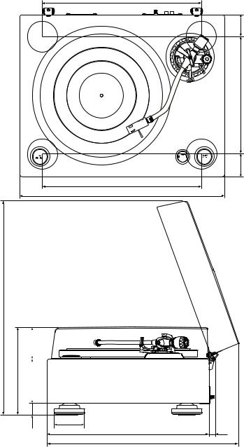
DIMENSION
n Total
Power supply : AC 120 V, 60 Hz Power consumption : 10 W
Maximum external dimensions :
With dust cover closed:
490 (W) ×213 (H) × 405 (D) mm (19-19/64” x 8-25/64” x 15-15/16”) With dust cover open:
490 (W) ×515 (H) × 465 (D) mm (19-19/64” x 20-9/32” x 18-5/16”) Weight : 15.7 kg (0.55 oz)
n Cartridge (DL-A100)
Power generation method : Moving coil (MC) type
Output voltage : 0.3 mV (1 kHz 50 mm/sec horizontally)
Channel balance : within 1 dB (1 kHz) Channel separation : more than 25dB (1 kHz) Impedance : 40 Ω ± 20 %
Compliance : 5 × 10⁻⁶ cm/dyne (used 100 Hz record) Stylus tip : 0.2 mm (1/64”) square solid diamond Stylus pressure : 2.5 g ± 0.3 g (0.09 oz ± 0.01 oz)
Frequency response : 20 Hz to 45 kHz
Weight : 8.8 g (0.31 oz)
Load resistance : more than 100 Ω (40 Ω when a transformer is used)
Maximum external dimensions :
15 (W) × 15 (H) × 26.8 (D) mm (19/32” x 19/32” x 1-1/16”)
320 |
53.5 |
280
53.5 |
320 |
490 |
515 max
|
75 |
|
|
210 |
|
|
|
|
|
|
|
105 |
|
||
|
|||
|
|
|
|
30 |
72 |
|
|
387 |
14 |
||
|
|||
|
465 max |
|
4
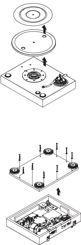
DISASSEMBLY
•Follow the procedure below in reverse order when reassembling.
•If wire bundles are untied or moved to perform adjustment or parts replacement etc., be sure to rearrange them neatly as they were originally bundled or placed afterward.
Otherwise, incorrect arrangement can be a cause of noise generation.
1.Platter
(1)Detach the rubber mat to the arrow direction.
(2)Put a finger through the round hold in the platter and lift straight up to remove the platter.
2.Bottom Cover
(1)Place the set upside down so that the tone arm base does not hit the installation rack and so that the cabinet does not get scratched.
(2)Remove 9 screws from the bottom side.
(3)Detach the Bottom Cover to the arrow direction.
5
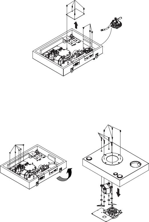
3.Main P.W.B. unit and Tone Arm Base
(1)Remove 4 screws q from the Main P.W.B. unit.
(2)Remove the soldering from the tone arm signal wire connected to the output board. When assembling, solder as indicated on the wiring diagram.
(3)Holding the tone arm base down, remove the 3 screws e fixing the tone arm base.
q
w
4.Motor unit P.W.B and Power Trans
(1)Remove 5 screws e from the Motor unit P.W.B..
(2)Remove the soldering from the ground wire connecting the Motor unit P.W.B. and output board.
(3)Turn the set upside down.
(4)Holding the motor unit board down, remove the 4 screws r fixing the Motor unit P.W.B..
(5)Holding down the nuts t, remove the 4 screws y fixing the transformer.
r
y
e
t |
t |
6
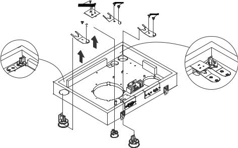
5.KNOB ASS'Y
(1)Remove the 2 screws u each fixing the KNOB ASS'Y fixing plate.
(2)Remove the 3 screws i each fixing the 33/45 unit P.W.B..
(3)Pull out the KNOB ASS'Y fixing plate and remove the KNOB ASS'Y.
|
u |
i |
u |
|
u


7
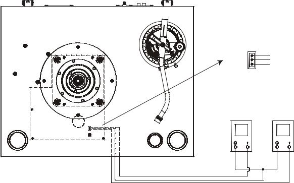
ADJUSTMENT
Electrical Adjustment for Wow and Flutter
(1)Detach the turntable and turn over the set.
(2)Open the bottom cover.
(3)Connect a digital volt meter or tester to CN104 (3P) on the Motor P.W.B..
(4)Turn on the power. Set the speed to 33 rpm.
(5)Insert a screwdriver into R134 (variable resistor) and adjust so that the absolute values of the two digital volt meters or testers are closest.
CN104 |
|
Motor+ |
|
GND |
|
Motor- |
|
Digital volt meter |
Digital volt meter |
or Tester |
or Tester |
(1) |
(2) |
CN104 |
|
R134 |
|
8

BLOCK DIAGRAM
9
Loading...