


S/M No. : TCM905FEF0
Service Manual
Colour Television
CHASSIS : CM-905F
Model : DTD-29U8ME 29U8MT 29U8MP 29U8MZ
MODEL OIPTION LIST
MODEL |
TEXT |
PIP |
|
|
|
ME |
O |
O |
|
|
|
MT |
O |
X |
|
|
|
MP |
X |
O |
|
|
|
MZ |
X |
X |
|
|
|
Caution
:In this Manual, some parts can be changed for improving, their performance without notice in the parts list. So, if you need the latest parts information,please refer to PPL(Parts Price List) in Service Information Center (http://svc.dwe.co.kr).
DAEWOO ELECTRONICS CO., LTD
http : //svc.dwe.co.kr |
NOVEMBER.2001 |

TABLE OF CONTENTS
SPECIFICATIONS .............................................................................................................. |
2 |
SAFETY INSTRUCTION .................................................................................................... |
3 |
CIRCUIT BLOCK DIAGRAM ............................................................................................. |
4 |
ALIGNMENT INSTRUCTIONS .......................................................................................... |
5 |
CM-905F TYPICAL SERVICE DATA .................................................................................. |
8 |
SCHEMATIC DIAGRAM ..................................................................................................... |
11 |
PRINTED CIRCUIT BOARD .............................................................................................. |
12 |
MECHANICAL EXPLODED VIEW AND PARTS LIST ...................................................... |
18 |
ELECTRICAL PARTS LIST ............................................................................................... |
19 |
CM-905F EACH MODEL PARTS LIST .............................................................................. |
28 |
APPENDIX (“Appendix is provided only by internet [http://svc.dwe.co.kr]”)
IC DESCRIPTION .............................................................................................................. |
1 |
TROUBLE SHOOTING CHARTS ...................................................................................... |
14 |
- 1 -

SPECIFICATIONS
Items |
Model |
DTD29U8ME |
|
|
29U8MT |
|
|
29U8MP |
|
|
29U8MZ |
|
|
|
TV Standards |
|
PAL-SECAM-B/G,D/K,I,NTSC-M,NTSC-4.43(AV) |
|
|
|
Mains Voltage |
|
AC 110~250V, 50/60Hz |
|
|
|
Power Consumption |
130Watts |
|
|
|
|
Sound Ouput |
|
7Watts + 7Watts Over (80% MOD.at 1KHz THD.10%) |
|
|
|
Speaker |
|
10W 8 Ohm (2 pcs) |
|
|
|
Antenna |
|
75 Ohm Unbalanced. (DIN Standard) |
|
|
|
Tuning System |
|
FS Tuning System |
|
|
|
Memory Channel |
100 Channels |
|
|
|
|
Remocon Control |
R-44C07 |
|
|
|
|
Reception Channel |
VHF - BAND1 : CH2 - CH4 |
|
|
|
BAND2 : CH5 - CH12 |
|
|
CABLE BAND : S1’ - S3, S1 - S20 |
|
|
HYPER BAND : S21 - S41 |
|
|
UHF-BAND 4,5 : CH21 - CH69 |
|
|
|
Remark |
|
OSD ( GUI Format ) |
|
|
TELETEXT ( Top & Flop Teletext ) |
|
|
PIP ( AV PIP, Swap, Size, Position ) |
|
|
Digital Eye |
|
|
|
- 2 -
SAFETY INSTRUCTION
NOTE
BEFORE SERVICING THIS CHASSIS READ THE “X-RAY RADIATION PRECAUTIONS”, “SAFETY PRECAUTIONS” AND “PRODUCT SAFETY NOTICE” BELOW.
X-RAY RADIATION PRECAUTIONS
1.Excessive high voltage can produce potentially hazardous X-RAY RADIATION.To avoid such hazards, the high voltage must not exceed the specified limit.The nominal value of the high voltage of this receiver is 29kV(29”) at max beam current.The high voltage must not, under any circumstances, exceed 30.5kV(29”). Each time a receiver requires servicing, the high voltage should be checked. It is recommended the reading
of the high voltage recorded as a part of the service recorded as a part of the service records. It is important to use an accurate and reliable high voltage meter.
2.The only source of X-RAY RADIATION in this TV receiver is the picture tube. For continuous RADIATION protection, the replacement tube must be exactly the same type tube as specified in the “PART LIST”.
SAFETY PRECAUTIONS
1.Potentials of high voltage are present when this receiver is operating. Operation of the receiver outside the cabinet or with the back cover removed involves a shock hazard from the receiver.
1)Servicing should not be attempted by anyone who is not thoroughly familiar with the precautions necessary when working on high voltage equipment.
2)Always discharge the picture tube to avoid the shock harzard before removing the anode cap.
3)Discharge the high potential of the picture tube before handling the tube.The picture tube is highly evacuated and if broken, glass fragments will be violently expelled.
2.If any FUSE in this TV receiver is blown, replace it will the FUSE specified in the “PART LIST”.
3.When replacing a high wattage resistor (oxide metal film resistor) in circuit board, keep the resistor 10mm away from circuit board.
4.Keep wires away from high voltage or high temperature components.
5.This receiver must operate between AC 110-250 volts, 50/60Hz. NEVER connect to DC supply or any other power or frequency.
PRODUCT SAFETY
Many electrical and mechanical parts in this chassis have special safety-related characteristics.
These characteristics are often passed unnoticed by a visual inspection and the X-RAY RADIATION protection afforded by them cannot necessarily be obtained by using replacement components rated for higher voltage, wattage, etc.
Replacement parts which have these special safety characteristics are identified in this manual and its supple-
ments, electrical components having such features are identified by designated symbol on the “PART LIST”. Before replacing any of these components, read the “PART LIST” in this manual carefully.
The use of substitute replacement part which do not have the same safety characteristics as specified in the “PART LIST” may created X-RAY RADIATION.
- 3 -
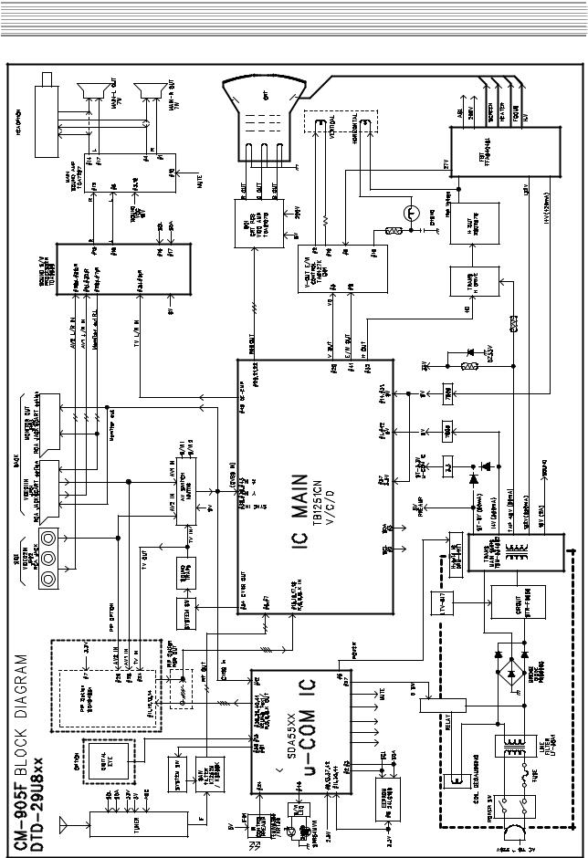
CIRCUIT BLOCK DIAGRAM
- 4 - |

ALIGNMENT INSTRUCTIONS
1.AGC ADJUSTMENT
1)Pattern : PAL B/G 10CH Color BAR (RF Level = 60 dB)
2)Connect the Pattern Generator RF Output to Tuner RF Input.
3)Press the S10 Key of Service Remocon to enter the “AGC MODE”.
4)Execute the “AUTO AGC” using the Vol-Up Key.
2.SCREEN ADJUSTMENT
1)Pattern : PAL B/G Retma
2)Press the NORMAL Key to set the “NORMAL 1” mode.
3)Press the S2 Key of Service Remocon.
4)Adjust the SCREEN VOLUME on FBT so that the horizontal line reach the cut-off point.
3.FOCUS ADJUSTMENT
1)Pattern : PAL B/G Retma
2)Adjust the FOCUS VOLUME on FBT to obtain clear resolution.
4.WHITE BALANCE ADJUSTMENT
1)Press the NORMAL Key to set the “NORMAL 1” mode.
2)Press the S8 Key of Service Remocon to enter the “WHITE BALANCE” mode.
3)Adjust the each color ( R,G,B ) which appears abnormally on the screen.
5.GEOMETRIC ADJUSTMENT
1)Press the NORMAL Key to set the “NORMAL 1” mode.
2)Press the S6 Key of Service Remocon to enter the “GEOMETRIC” mode.
5-1.VERTICAL CENTER ADJUSTMENT
1)Pattern : PAL B/G Retma
2)Choose the “V-CENTER” using the Pr-Up/Down Keys.
3)Adjust the horizontal line of picture to coincide with the mechanical center marks of the CRT using the
Vol-Up/Down Keys.
* If the pattern is smaller than the screen, adjust the V-size to fit.
5-2.VERTICAL SIZE ADJUSTMENT
1)Pattern : PAL B/G Retma
2)Choose the “V-SIZE” using the Pr-Up/Down Keys.
3)Adjust the vertical size of the picture using the Vol-Up/Down Keys.
- 5 -
ALIGNMENT INSTRUCTIONS
5-3. HORIZONTAL CENTER ADJUSTMENT
1)Pattern : PAL B/G Retma
2)Choose the “H-CENTER” using the Pr-Up/Down Keys.
3) Adjust the vertical line of picture to coincide with the mechanical center marks of the CRT using the Vol-Up/Down Keys.
5-4. HORIZONTAL SIZE ADJUSTMENT
1)Pattern : PAL B/G Retma
2)Choose the “H-SIZE” using the Pr-Up/Down Keys.
3)Set each side over scan to be 10% using the Vol-up/Down Keys.
5-5. PINCUSHION ADJUSTMENT
1)Pattern : PAL B/G Crosshatch
2)Choose the “PARABOLA” using the Pr-Up/Down Keys. Adjust parabola width to fit on screen.
3)Choose the “CORNER” using the Pr-Up/Down Keys. Adjust coner parabola to fit on screen.
4)Choose the “TRAPEZIUM” using the Pr-Up/Down Keys, Adjust trapezium to fit on screen.
5-6. S-CORRECTION ADJUSTMENT
1)Pattern : PAL B/G Crosshatch
2)Choose the “S-CORRECTION” using the Pr-Up/Down Keys.
3)Adjust each distance of horizontal line to be the same using the Vol-Up/Down Keys.
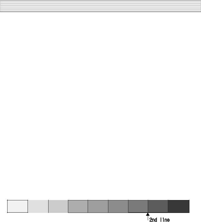
5-7. SUB-BRIGHTNESS ADJUSTMENT
1)Pattern : PAL B/G Retma
2)Press the NORMAL Keys to set the “NORMAL 1” mode.
3)Adjust the Brightness so that the second line of top appears, as follow.
- 6 -
ALIGNMENT INSTRUCTIONS
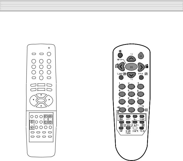
6. REMOCON |
|
6-1. SERVICE REMOCON |
6-2. USER REMOCON |
RECALL MUTE |
POWER |
|
S1
S4
S7
S10
TV/CATV
S2 |
S3 |
S5 |
S6 |
S8 |
S9 |
|
S12 |
S11 |
|
ADD/ERASE |
TV/VIDEO |
SOUND |
MODE |
SURROUND
NOISE CLEAR
|
|
CH |
|
|
VOL |
MENU |
|
VOL |
|
|
|
|||
|
|
CH |
|
|
PIP |
POSITION |
M/S |
|
|
|
TV/VIDEO |
PAUSE/ |
CH |
VOL |
|
STILL |
|||
V- |
|
|
1 |
2 |
POSITION |
SIZE |
SLEEP |
||
3 |
4 |
|
5 |
6 |
7 |
8 |
|
9 |
0 |
R-34SVC
6-3. SERVICE REMOCON
1)Enter SERVICE MODE : Press keys of User Remocon, as follows. Ch91, Sharpness 0, Skip(red), Move(green), Menu.
2)Choice SERVICE MENU : Pr-Up/Down
3)Enter SERVICE SUB MENU :Vol-Up/Down
4)Adjust SERVICE MENU :Vol-Up/Down
- 7 -

CM-905F TYPICAL SERVICE DATA
CM-905F SVC KEY & FUNCTION DESCRIPTION
EY N |
NAME |
|
RFUNCTION |
|
|
||
|
|
|
|
|
|
||
|
|
|
|
|
|
||
S1 |
HEATRUN MODE |
PRESS THE S1 ONE TINE ----> PRESS THE S1 ANOTHER TIME |
ON/OFF |
||||
(HEATRUN MODE) |
(NORMAL OPRATION) |
||||||
|
|
|
|
||||
|
|
|
|
|
|
||
|
SCREEN |
* FBT SCREEN ADJUSTMENT |
|
|
|||
S2 |
PRESS THE S2 ON TIME ----> PRESS THE S2 ANOTHER TIME |
ON/OFF |
|||||
ADJUSTMENT |
|||||||
|
|
|
|
||||
|
(HORIZONTAL KINE) |
|
(NORMAL OPRATION) |
||||
|
|
|
|
|
|||
|
|
|
|
|
|
|
|
|
|
|
* SOUND TEST |
|
|
||
S3 |
SOUND TEST |
PRESS THE S3 KEY IS TOGGLE |
|
|
|||
|
|
|
Line Production |
||||
VOLUME 00 ----> VOLUME 32 ----> VOLUME 63---> |
|||||||
|
|
||||||
|
|
|
|
|
|
||
|
|
BALANS LEFT ----> BALANS RIGHT ----> BALANS 00 ----> RELEASE |
|
|
|||
|
|
|
|
|
|
|
|
|
|
|
* PICTURE TEST |
|
|
||
S4 |
PICTURE TEST |
PRESS THE S4 KEY IS TOGGLE |
|
|
|||
|
|
|
Line Production |
||||
CONTRAST 00 ----> CONTRASR 32 ----> CONTRAST 63 ----> |
|||||||
|
|
||||||
|
|
|
|
|
|
||
|
|
RRIGHT 00 ----> BRIGHT 32 ----> BRIGHT 63 ----> |
|
|
|||
|
|
|
|
|
|
||
|
|
COLOR 00 ----> COLOR 32 ----> COLOR 63 ----> RELEASE |
|
|
|||
|
|
|
|
|
|
|
|
|
|
|
* ADJUST NORMAL1 DATA |
INITIAL DATA |
|||
|
|
|
CONTRAST 63 |
63 |
|
||
S5 |
NORMAL1 |
|
RRIGHT 32 |
32 |
|
||
|
|
|
|
|
|
|
|
|
|
|
COLOR 32 |
32 |
|
||
|
|
|
|
|
|
|
|
|
|
|
SHARPNESS 32 |
32 |
|
||
|
NAME |
* ADJUST GEOMETRY DATA |
|
|
|||
|
|
PAL MODE |
|
NTSC MODE |
INITIAL DATA(50Hz) |
||
|
|
|
|
|
|
|
|
|
V-CENTER |
05 |
|
03 |
04 |
|
|
|
V-SIZE |
39 |
|
39 |
27 |
|
|
|
H-CENTER |
08 |
|
12 |
14 |
|
|
|
H-SIZE |
36 |
|
36 |
58 |
|
|
|
|
|
|
|
|
|
|
S6 |
PARABORA |
32 |
|
32 |
27 |
|
|
|
|
|
|
|
|
|
|
|
TRAPEZIUM |
16 |
|
16 |
15 |
|
|
|
|
|
|
|
|
|
|
|
CORNER |
06 |
|
06 |
05 |
|
|
|
|
|
|
|
|
|
|
|
H-EHT |
03 |
|
03 |
03 |
|
|
|
S-CORRECTION |
09 |
|
09 |
07 |
|
|
|
V-LINEARITY |
08 |
|
08 |
09 |
|
|
|
V-EHT |
03 |
|
03 |
03 |
|
|
|
PIP |
|
* ADJUST PIP DATA |
INITIAL DATA |
|||
S7 |
|
|
|
|
|
|
|
R |
|
180 |
128 |
|
|||
|
|
|
|||||
|
G |
|
180 |
128 |
|
||
|
|
|
|
|
|
||
|
B |
|
180 |
128 |
|
||
|
|
|
|
|
|
|
|
- 8 -
CM-905F TYPICAL SERVICE DATA
CM-905F SVC KEY & FUNCTION DESCRIPTION
|
|
WHITE BALANCE |
* ADJUST WHITE BALANCE DATA |
|
|
|
|
|
RB |
R LOW BEAM ADJUSTMENT |
|
128 |
|
|
|
|
|
|
|
|
S8 |
GB |
G LOW BEAM ADJUSTMENT |
|
0 |
|
|
|
|
|
|
|
||
BB |
B LOW BEAM ADJUSTMENT |
|
0 |
|
||
|
|
|
|
|||
|
|
|
|
|
|
|
|
|
GG |
G HIGH BEAM ADJUSTMENT |
|
64 |
|
|
|
|
|
|
|
|
|
|
BG |
B HIGH BEAM ADJUSTMENT |
|
32 |
|
|
|
|
|
|
|
|
S9 |
SUB-BRIGHT |
ADJUST BRIGHTNESS DATA |
|
15 |
|
|
|
|
|
|
|
||
SUB-CONTRAST |
ADJUST SUB CONTRAST DATA |
|
15 |
|
||
|
|
|
|
|||
|
|
|
|
|
|
|
|
|
|
* MAIN RF AGC ADJUSTMENT KEY |
|
|
|
S10 |
|
AGC |
TUNER AGC VOLTAGE 3.5Vdc |
|
|
|
|
AUTO-AGC |
|
|
|
|
|
|
|
|
|
|
|
|
|
|
|
|
|
|
|
|
|
DATA |
32 |
|
|
|
|
|
|
|
|
|
|
|
|
|
* OPTION MODE ADJUSTMENT KEY |
|
INITIAL DATA |
|
S11 |
TEXT |
ARABIC/CYRILLIC/IRANIAN/EAST-LATIN//WEST-LATIN |
|
ARABIC |
||
|
|
|
|
|
||
POWER-ON-START |
ON/OFF |
|
ON |
|||
|
|
|
||||
|
|
DIGITAL EYE |
ON/OFF |
|
ON |
|
|
|
|
|
|
|
|
|
|
|
* OUT DATA |
|
|
|
|
|
PICTURE |
NORMAL 1 |
|
|
|
|
|
|
|
|
|
|
|
|
BLUE SCREEN |
ON |
|
|
|
|
|
|
|
|
|
|
|
|
CLOCK |
|
|
|
|
|
|
|
|
|
|
|
|
|
ON TIMER |
|
|
|
|
|
|
|
|
|
|
|
|
|
ON TIMER |
OFF |
|
|
|
|
|
ON/OFF |
|
|
||
|
|
|
|
|
|
|
|
|
ON PR |
1 |
|
|
|
|
|
OFF TIMER |
|
|
|
|
S12 |
OFF TIMER |
OFF |
|
|
||
|
|
ON/OFF |
|
|
||
|
|
|
|
|
|
|
|
|
|
|
|
|
|
|
|
LANGUAGE |
ENGLISH |
|
|
|
|
|
|
|
|
|
|
|
|
COLOR SYSTEM |
PAL |
|
|
|
|
|
SOUND SYSTEM |
BG |
|
|
|
|
|
|
|
|
|
|
|
|
SOUND MODE |
MEMORY |
|
|
|
|
|
NAME(EACH PR) |
---- |
|
|
|
|
|
|
|
|
|
|
|
|
TV/AV1/AV2 |
TV |
|
|
|
|
|
|
|
|
|
|
|
|
TV/TEXT |
TV |
|
|
|
|
|
LAST PR |
1 |
|
|
|
|
|
VOLUME |
20 |
|
|
|
|
|
|
|
|
|
|
|
|
PICTURE SIZE |
NORMAL (4:3) |
|
|
|
|
|
|
|
|
|
|
- 9 -
CM-905S/SF TYPICAL SERVICE DATA
CM-905 SVC KEY & FUNCTION DESCRIPTION
S12 |
CHILD LOCK |
OFF |
|
CH LOCK |
OFF |
|
|
|
|
||
|
|
|
|
SUB MENU
NO |
NAME |
SERVICE |
RFUNCTION |
|
IITIAL DATA |
|
|
|
REMOCON |
|
|
|
|
|
|
NAME |
|
|
|
|
|
|
|
|
|
|
|
1 |
PIP ON / OFF (PIP) |
PIP |
ON/OFF display a sub-picture |
|
OFF |
|
|
|
|
|
|
|
|
2 |
SWAP (PIP) |
M/S |
The main picture and sub-picture are swapped |
|
||
|
|
PAUSE/ |
The sub-picture will be smaller. |
|
|
|
3 |
SIZE (PIP) |
To return to be normal size, Press this button |
|
|||
STILL |
|
|||||
|
|
again. |
|
|
||
|
|
|
|
|
||
|
|
|
|
|
|
|
4 |
TV / VIDEO (PIP) |
TV/VIDEO |
To select the input for the sub pictrue |
|
|
|
|
|
|
|
|
||
5 |
POSITION (PIP) |
POSITION |
The display position of the sub-picture will changed |
|
||
|
|
|
|
|
|
|
|
|
|
S2 DATA changed |
|
|
|
|
|
|
RB |
|
128 |
128 |
|
|
|
GB |
|
0 |
0 |
6 |
SCREEN |
V-POSITION |
BB |
|
0 |
0 |
|
|
|
GG |
|
64 |
64 |
|
|
|
BG |
|
64 |
64 |
|
|
|
Brightness |
|
32 |
32 |
7 |
DIGITAL EYE |
V-POSITION |
DIGITAL EYE funtion ON/OFF |
|
|
|
|
|
|
||||
|
|
|
|
|
|
|
8 |
ZOOM |
SIZE |
Picture size changed ( 4:3 -> 16:9 -> ZOOM -> 4:3 ->) |
|
||
9 |
TEXT |
SLEEP |
TEXT funtion ON/OFF |
|
|
|
10 |
CH UP |
CH |
USING the SERVICE MODE to Channel UP/DOWN |
|
||
11 |
CH DOWN |
CH |
|
|||
|
|
|
|
|||
12 |
RESISTER |
VOL |
USING the FACTIRY KEY |
|
|
|
13 |
RELEASE |
VOL |
|
|
||
|
|
|
|
|||
- 10 -

SCHEMATIC DIAGRAM
11 |

PRINTED CIRCUIT BOARD
PCB MAIN
- 12 -

PRINTED CIRCUIT BOARD
- 13 -

PRINTED CIRCUIT BOARD
- 14 -
 Loading...