


CP-185

Service Manual
Chassis : CP-185
S/M No. : TCP185MEF0
http : //svc.dwe.co.kr JUN. 2000
DAEWOO ELECTRONICS CO., LTD.
SPECIFICATIONS
Version
TF
TK
TU
TA
TV standard
PAL B/G PAL-SECAM B/G – D/K PAL I/I PAL B/G – SECAM L/L
’
Sound system
mono
Power consumption
14”: 39W; 20 ”: 42W; 21 ”: 45W.
Sound Output Power
2.5W (at 60% mod, 10%THD)
Speaker
3W 8 ohm
Teletext system
10 pages memory FASTEXT (FLOF or TOP)
– version with teletext only
Aerial input
75 ohm unbalanced
Channel coverage
Off-air channels, S-cable channels and hyperband
Tuning system
frequency synthesiser tuning system
Visual screen size
14 ” : 34 cm
20 ” : 48 cm
21 ” : 51 cm
Channel indication
On Screen Display
Program Selection
100 programmes
Aux. terminal
EURO-SCART : Audio / Video In and Out,
R/G/B In, Slow and Fast switching, SVHS In.
Audio-Video Jack on front of cabinet in common
connection with EURO-SCART.
Headphone jack (3.5 mm) on front of cabinet
Remote Control Unit
R-40A01
Colour Television
Model : DTA - 14C4TFF
DTA - 20C4TF
DTA - 14V1TF
DTA - 21C6TFF

1
TABLE OF CONTENTS
SAFETY INSTRUCTION .................................................................................................................. 2
SPECIFICATIONS ............................................................................................................................ 3
1. 21 Pin EURO-SCART ................................................................................................................... 3
2. Channel table ............................................................................................................................... 4
3. ATTS sorting method .................................................................................................................... 6
CIRCUIT BLOCK DIAGRAM ........................................................................................................... 8
ALIGNMENT INSTRUCTION ........................................................................................................... 9
1. Service mode ................................................................................................................................ 9
2. Microcontroller configuration ........................................................................................................ 9
3. TV set Alignment .......................................................................................................................... 9
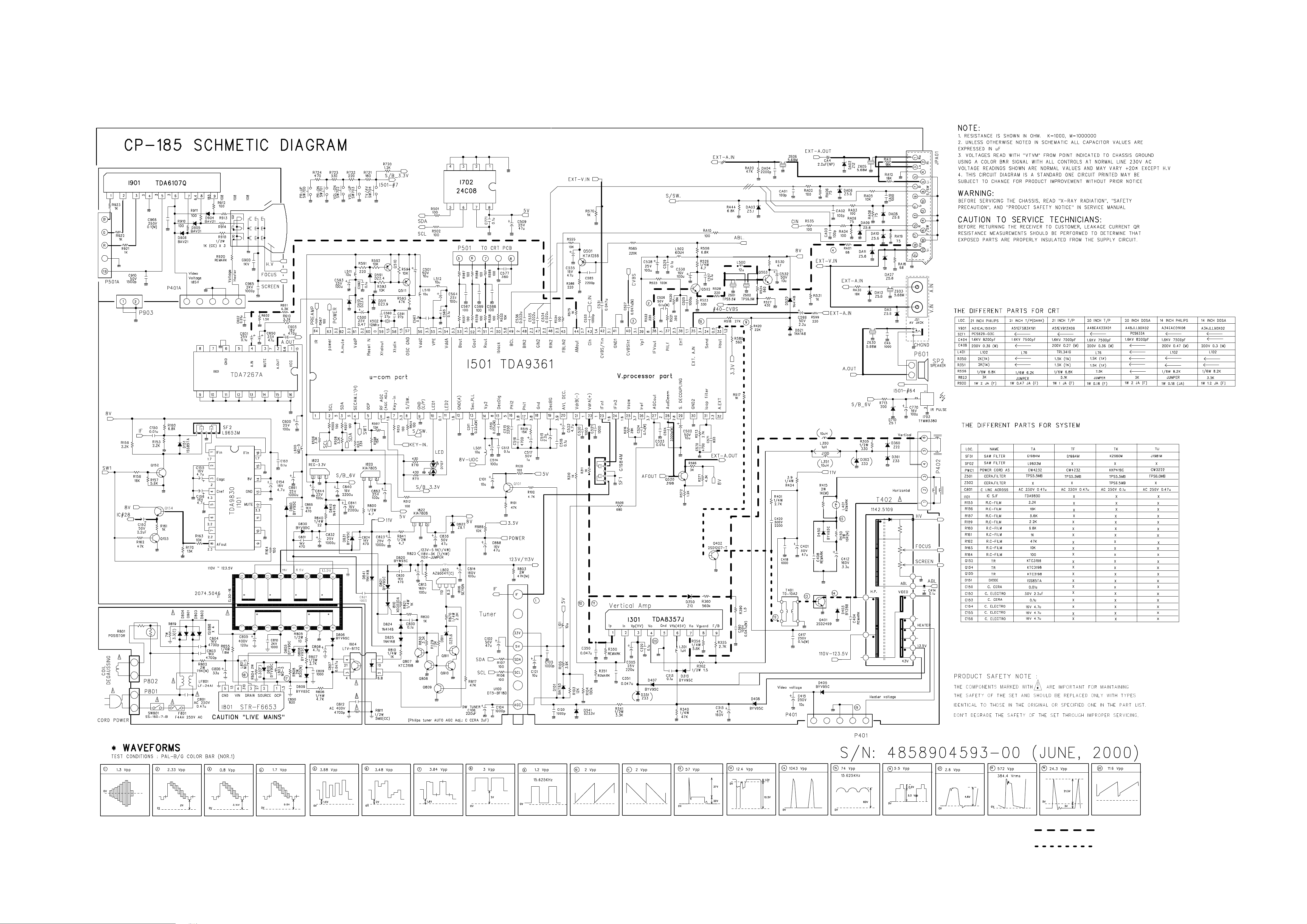
SCHEMATIC DIAGRAM .................................................................................................................. 11
EXPLODED VIEW ............................................................................................................................ 11
PRINTED CIRCUIT BOARD ............................................................................................................ 12
SERVICE PARTS LIST .................................................................................................................... 13
1. The Different Parts List ................................................................................................................. 18
APPENDIX (" Appendix is provided only by internet [http://svc.dwe.co.kr] ")
FUNCTIONAL DESCRIPTION ......................................................................................................... 1
IC DESCRIPTION ............................................................................................................................. 16

2
SAFETY INSTRUCTION
WARNING :
Only competent service personnel may carry out work involving the testing or repair of this equipment
1. Excessive high voltage can produce potentially hazardous X-RAY RADIATION. To avoid such hazards, the high
voltage must not exceed the specified limit. The nominal value of the high voltage of this receiver is 22-23 kV (14”) or
24-26 kV (20” - 21”) at max beam current. The high voltage must not, under any circumstances, exceed 27.5 kV (14”,
20”), 29KV (21”). Each time a receiver requires servicing, the high voltage should be checked. It is important to use an
accurate and reliable high voltage meter.
2. The only source of X-RAY Radiation in this TV receiver is the picture tube. For continued X-RAY RADIATION
protection, the replacement tube must be exactly the same type tube as specified in the parts list.
X-RAY RADIATION PRECAUTION
1. Potentials of high voltage are present when this receiver is operating. Operation of the receiver outside the cabinet or
with the back cover removed involves a shock hazard from the receiver.
1)Servicing should not be attempted by anyone who is not thoroughly familiar with the precautions necessary when
working on high voltage equipment.
2)Discharge the high potential of the picture tube before handling the tube. The picture tube is highly evacuated and if
broken, glass fragments will be violently expelled.
2. If any Fuse in this TV receiver is blown, replace it with the FUSE specified in the Replacement Parts List.
3. When replacing a high wattage resistor (oxide metal film resistor) in circuit board, keep the resistor body 10 mm away
from the circuit board.
4. Keep wires away from high voltage or high temperature components.
5. This receiver must operate under AC 230 volts, 5O Hz. NEVER connect to a DC supply of any other voltage or
frequency.
SAFETY PRECAUTION
Many electrical and mechanical parts in this equipment have special safety-related characteristics. These characteristics are
often passed unnoticed by a visual inspection and the X-RAY RADIATION protection afforded by them cannot necessarily be
obtained by using replacement components rated for higher voltage, wattage, etc. Replacement parts which have these spe-
cial safety characteristics are identified in this manual and its supplements, electrical components having such features are
identified by designated symbol on the parts list. Before replacing any of these components, read the parts list in this manual
carefully. The use of substitutes replacement parts which do not have the same safety characteristics as specified in the parts
list may create X-RAY Radiation.
PRODUCT SAFETY NOTICE
3
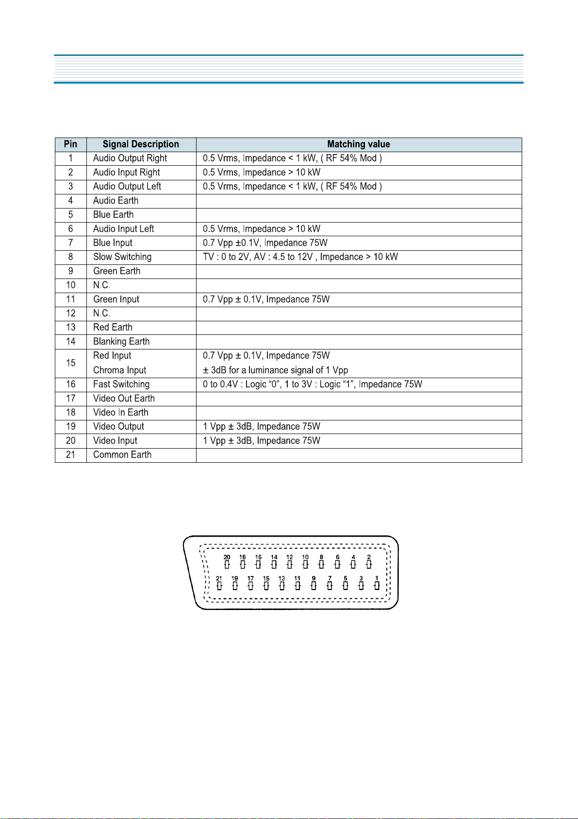
Pin EURO-SCART :
SPECIFICATIONS
4
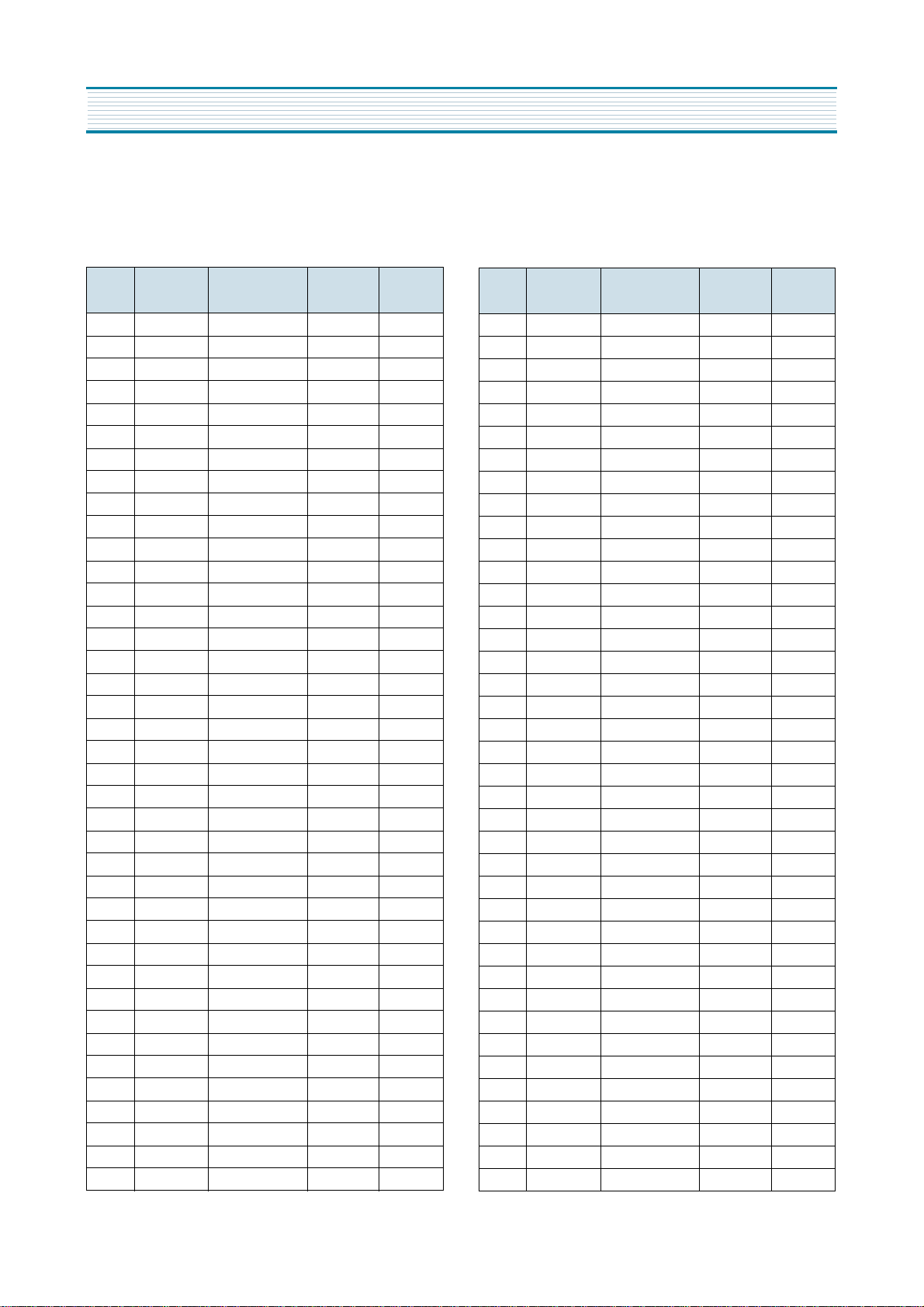
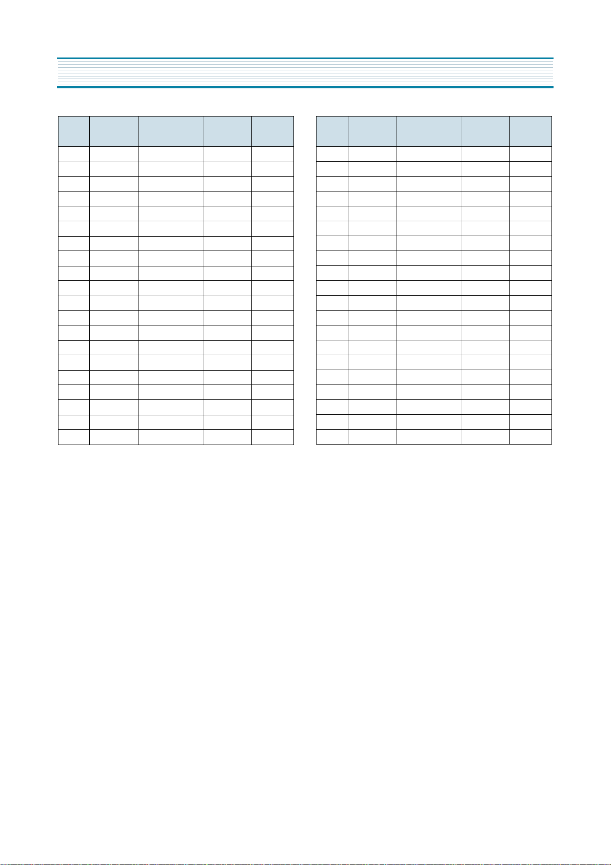
Channel table
FREQUENCY TABLE CP185
CH
EUROP
E CCIR
FRANCE
GB(IRE-
LAND)
EAST
OIRT
C01 46.25 - 45.75 49.75
C02 48.25 55.75 (L') 53.75 59.25
C03 55.25 60.5 (L') 61.75 77.25
C04 62.25 63.75 (L') 175.25 85.25
C05 175.25 176.00 183.25 93.25
C06 182.25 184.00 191.25 175.25
C07 189.25 192.00 199.25 183.25
C08 196.25 200.00 207.25 191.25
C09 203.25 208.00 215.25 199.25
C10 210.25 216.00 223.25 207.25
C11 217.25 189.25 (LUX) 231.25 215.25
C12 224.25 69.25 (L') 239.25 223.25
C13 53.75 76.25 (L') 247.25 -
C14 - 83.25 (L') 49.75 -
C15 82.25 90.25 57.75 -
C16 - 97.25 65.75 -
C17 183.75 - 77.75 -
C18 192.25 - 85.75 -
C19 201.25 - - -
C20 - - - -
C21 471.25 471.25 471.25 471.25
C22 479.25 479.25 479.25 479.25
C23 487.25 487.25 487.25 487.25
C24 495.25 495.25 495.25 495.25
C25 503.25 503.25 503.25 503.25
C26 511.25 511.25 511.25 511.25
C27 519.25 519.25 519.25 519.25
C28 527.25 527.25 527.25 527.25
C29 535.25 535.25 535.25 535.25
C30 543.25 543.25 543.25 543.25
C31 551.25 551.25 551.25 551.25
C32 559.25 559.25 559.25 559.25
C33 567.25 567.25 567.25 567.25
C34 575.25 575.25 575.25 575.25
C35 583.25 583.25 583.25 583.25
C36 591.25 591.25 591.25 591.25
C37 599.25 599.25 599.25 599.25
C38 607.25 607.25 607.25 607.25
C39 615.25 615.25 615.25 615.25
SPECIFICATIONS
CH
EUROP
E CCIR
FRANCE
GB(IRE-
LAND)
EAST
OIRT
C40 623.25 623.25 623.25 623.25
C41 631.25 631.25 631.25 631.25
C42 639.25 639.25 639.25 639.25
C43 647.25 647.25 647.25 647.25
C44 655.25 655.25 655.25 655.25
C45 663.25 663.25 663.25 663.25
C46 671.25 671.25 671.25 671.25
C47 679.25 679.25 679.25 679.25
C48 687.25 687.25 687.25 687.25
C49 695.25 695.25 695.25 695.25
C50 703.25 703.25 703.25 703.25
C51 711.25 711.25 711.25 711.25
C52 719.25 719.25 719.25 719.25
C53 727.25 727.25 727.25 727.25
C54 735.25 735.25 735.25 735.25
C55 743.25 743.25 743.25 743.25
C56 751.25 751.25 751.25 751.25
C57 759.25 759.25 759.25 759.25
C58 767.25 767.25 767.25 767.25
C59 775.25 775.25 775.25 775.25
C60 783.25 783.25 783.25 783.25
C61 791.25 791.25 791.25 791.25
C62 799.25 799.25 799.25 799.25
C63 807.25 807.25 807.25 807.25
C64 815.25 815.25 815.25 815.25
C65 823.25 823.25 823.25 823.25
C66 831.25 831.25 831.25 831.25
C67 839.25 839.25 839.25 839.25
C68 847.25 847.25 847.25 847.25
C69 855.25 855.25 855.25 855.25
C70 863.25 863.25 863.25 863.25
C71 69.25 - - -
C72 76.25 - - -
C73 83.25 - - -
C74 90.25 - - -
C75 97.25 - - -
C76 59.25 - - -
C77 93.25 - - -
S01 105.25 104.75 103.25 105.25
5
CH
EUROP
E CCIR
FRANCE
GB(IRE-
LAND)
EAST
OIRT
S02 112.25 116.75 111.25 112.25
S03 119.25 128.75 119.25 119.25
S04 126.25 140.75 127.25 126.25
S05 133.25 152.75 135.25 133.25
S06 140.25 164.75 143.25 140.25
S07 147.25 176.75 151.25 147.25
S08 154.25 188.75 159.25 154.25
S09 161.25 200.75 167.25 161.25
S10 168.25 212.75 - 168.25
S11 231.25 224.75 - 231.25
S12 238.25 236.75 - 238.25
S13 245.25 248.75 255.25 245.25
S14 252.25 260.75 263.25 252.25
S15 259.25 272.75 271.25 259.25
S16 266.25 284.75 279.25 266.25
S17 273.25 296.75 287.25 273.25
S18 280.25 136.00 295.25 280.25
S19 287.25 160.00 303.25 287.25
S20 294.25 - - 294.25
S21 303.25 303.25 - 303.25
SPECIFICATIONS
CH
EUROP
E CCIR
FRANCE
GB(IRE-
LAND)
EAST
OIRT
S22 311.25 311.25 311.25 311.25
S23 319.25 319.25 319.25 319.25
S24 327.25 327.25 327.25 327.25
S25 335.25 335.25 335.25 335.25
S26 343.25 343.25 343.25 343.25
S27 351.25 351.25 351.25 351.25
S28 359.25 359.25 359.25 359.25
S29 367.25 367.25 367.25 367.25
S30 375.25 375.25 375.25 375.25
S31 383.25 383.25 383.25 383.25
S32 391.25 391.25 391.25 391.25
S33 399.25 399.25 399.25 399.25
S34 407.25 407.25 407.25 407.25
S35 415.25 415.25 415.25 415.25
S36 423.25 423.25 423.25 423.25
S37 431.25 431.25 431.25 431.25
S38 439.25 439.25 439.25 439.25
S39 447.25 447.25 447.25 447.25
S40 455.25 455.25 455.25 455.25
S41 463.25 463.25 463.25 463.25
6
ATSS sorting method
The TV set sweeps all the TV bands from beginning of VHF to the end of UHF. The TV controlling software for each program
checks if a VPS CNI code is transmitted. If no VPS CNI code is found, the system checks if a CNI code is transmitted in the tele-
text lines ( Packet 8/30 format 1 ). If such a code ( VPS or teletext ) is found and if this code is in the ATSS list, the program is
automatically named.
The programs found are then sorted into 4 groups :
Group I
: Contains all the programs from the selected country and named by the TV controlling software. Within this group the
sorting order is fixed by the ATSS list.
Group II
: Contains all the programs with a strong signal strength which are not listed in group I.
Group III
: Contains all the programs with a weak signal strength which are not listed in group I.
Group IV
: If two or more programs with the same code are found, only the strongest (or if they have the same level the one
with the lowest frequency) is listed in group I, II or III. The others are listed in group IV.
Note : If two programs with the same name but a different code are found these two programs are listed in group I, II or III (e.g.
Regional program SW3 in Germany).
The sorting order within group II, III, and IV is based on the channel frequency. The program with the lowest frequency is allo-
cated the first rank in its group, and so forth until the last program of the group which has the highest frequency.
Program number Group Skip
1
2 Group I
...
n
n+1
... Group II
m
m+1
... Group III
p
p+1
... Group IV
q
q+1
... not used 4
99
0
Special case :
Country selection = Others
Program number Group Skip
1
... Group II
m
m+1
... Group III
p
p+1
... Group IV
q
q+1
... not used 4
99
0
For TV versions without teletext, and if the controlling software is unable to catch the station name,
Group I will remain empty.
Note
SPECIFICATIONS

7
Special case :
France
If France is selected the TV controlling software firstly sweeps all the TV bands with France system selected (positive video
modulation) and secondly with Europe system selected (negative video modulation).
Special case :
Switzerland
If Switzerland is selected the TV controlling software firstly sweeps all the TV bands with Europe system selected (negative
video modulation) and secondly with France system selected (positive video modulation).
Special case :
GB
Note for satellite receiver users : Before starting ATSS turn On your satellite receiver and tune “ SKY NEWS “.
If GB is selected the TV controlling software seeks for programs only in UHF ( C21 to C70 ). The sorting order is :
1 - BBC1
2 - BBC2
3 - ITV
4 - CH4
5 - CH5
6 - NEWS
If two or more “ identical “programs ( same name but different code e.g. BBC1 and BBC1 Scotland ) are found the following pro-
grams in the list will be shifted up. (1 - BBC1, 2 - BBC1, 3 - BBC2, 4 - ITV, 5 - CH4, 6 - CH5, 7 - NEWS, ..)
If one of the program above is not found, the associated program number remains empty ( freq.=467.25 MHz - Skip selected -
no name – system = GB).
example A : 1 - BBC1, 2 - BBC2, 3 - ITV, 4 - -----, 5 - CH5, 6 - NEWS, ...
example B ( if 2 BBC1 found ) : 1 - BBC1, 2 - BBC1, 3 - BBC2, 4 - ITV, 5 - -----, 6 - CH5, 7 - NEWS, ...
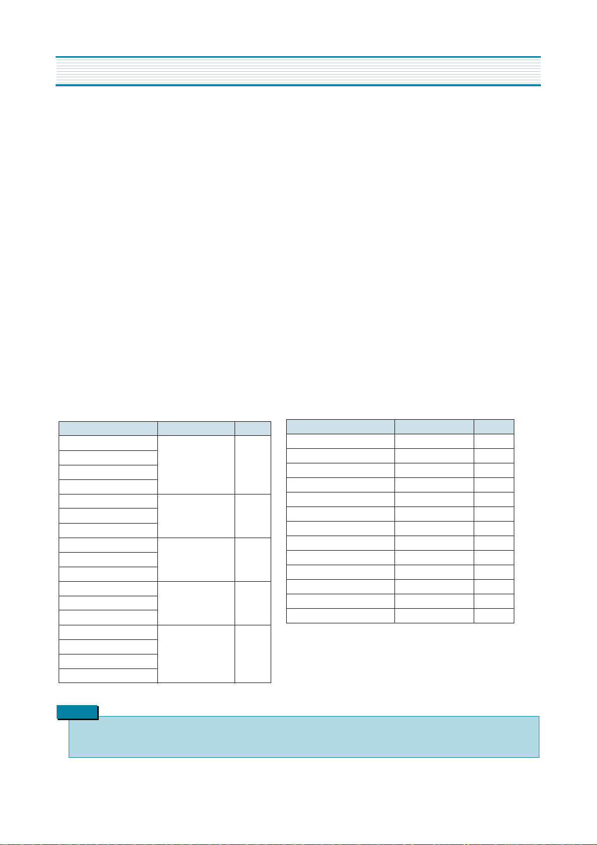
Version TF TK TU TA
ATSS countries
Germany, Belgium,
Spain, Italy,
Austria, Denmark,
Finland,
Netherlands, Norway,
Sweden,
Others
Germany, Belgium,
Spain, Italy,
Austria, Denmark,
Finland,
Netherlands,
Norway, Sweden,
Poland, Hungary,
Czech Rep, Others
GB, Ireland, Others France,
Switzerland,
Germany, Belgium,
Spain, Italy,
Austria, Denmark,
Finland,
Netherlands,
Norway, Sweden,
Others
SPECIFICATIONS
8
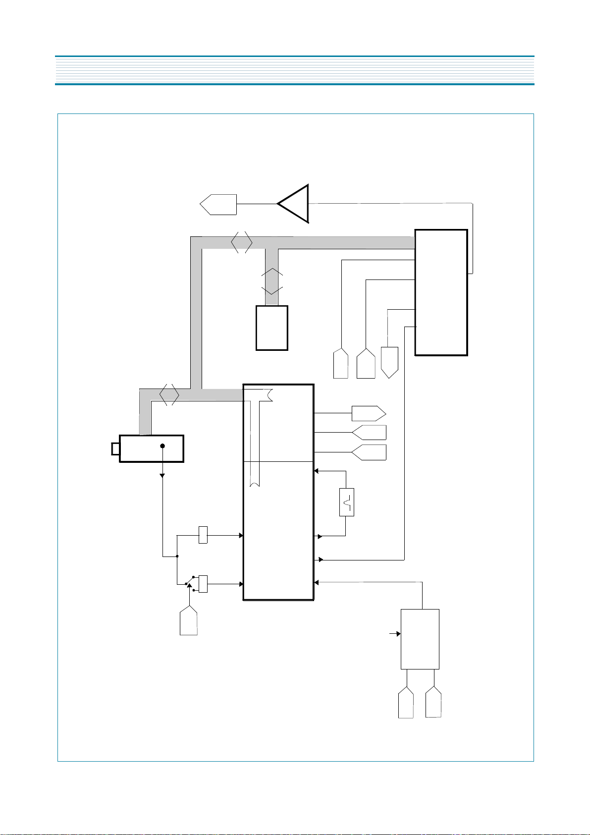
CIRCUIT BLOCK DIAGRAM
To speakers /
head phones
IIC BUS
IF
IF = 38.9 MHz (All standard except L')
= 33.9 MHz (L')
Video IF
SF1 SF2
Audio IF
#4 - I501
#23
#24
#28
#29
Video processor
#38
#35
#42
#40#43
#46
#47
#48
#51
#52
#53
I501
Micro controller
#2 #3
video In
video
out
QSS
out
ext. video in
Trap 5.5MHz
SIF (5.5MHz for system B/G)
Audio out
SCART 1
Audio in
SCART 1
Audio in
SCART 2
#28
#29
#49
#50
#52
#53
#36
#37
#58
Sound processor
I601
Base bond signal
I602
Audio
Amplifier
Video in
SCART 1
SCART 2
Switching
circuit
switch control
from #8-I501
and #8 SCART 1
To CRT board
RGB out
ext RGB in
chroma in
9
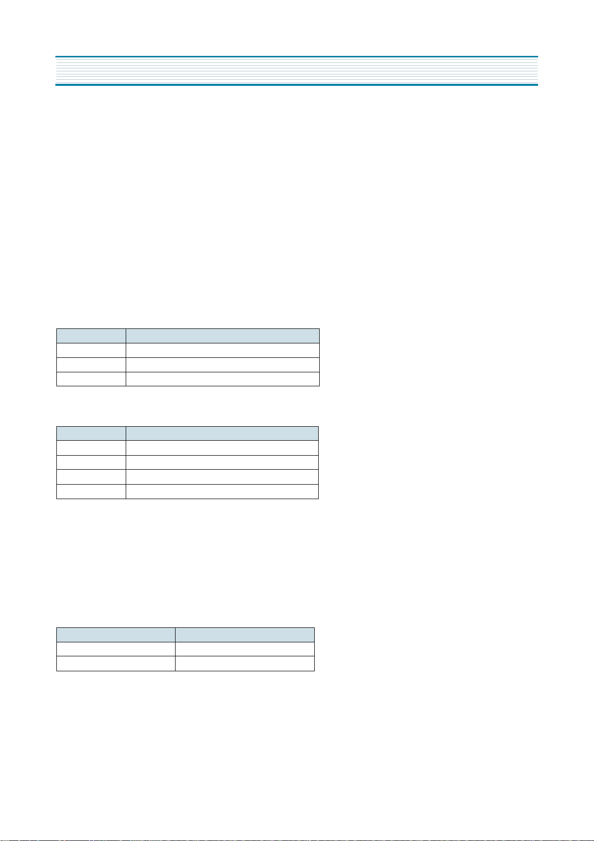
ALIGNMENT INSTRUCTIONS
Microcontroller configuration : Service mode
To switch the TV set into service mode please see instruction below.
1 - Select pr. number 91
2 - Adjust sharpness to minimum and exit all menu.
3 - Quickly press the key sequence : RED - GREEN - menu
To exit SERVICE menu press menu key or Std By key.
In Service Mode press “OK” to stop the microcontroller i.e. the I2C bus is free and the set can be controlled by external equipment.
Press “OK” again to allow the microcontroller to control the set again
Microcontroller configuration :
Tuner Option
System Option
TV set Alignment
1 - G2 alignment
- Set TV in NORMAL I mode
- TV in AV mode without video signal ? Black screen.
- TV preset with WP Red, WP Green and WP Blue equal to 32.
- TV preset with Black R, Black G equal to 8.
- Adjust screen volume ( on FBT ) such that the highest cathode cut-off voltage measured on CRT board, is Vcut-off ± 5V.
2 - White balance
- Select a dark picture and adjust Black G and Black R to the desired colour temperature.
- Select a bright picture and adjust WP Red, WP Green, WP Blue to the desired colour temperature.
Option Tuner maker
DW DAEWOO / SAMSUNG
PH1 PHILIPS ( Video processor AGC )
PH2 PHILIPS (tuner internal AGC )
Option System
TF PAL – B/G
TK PAL – SECAM B/G-D/K
TU PAL I/I
TA PAL – SECAM B/G-L/L’
Screen size Vcut-off
14” 115 V
20” & 21” 125 V
10
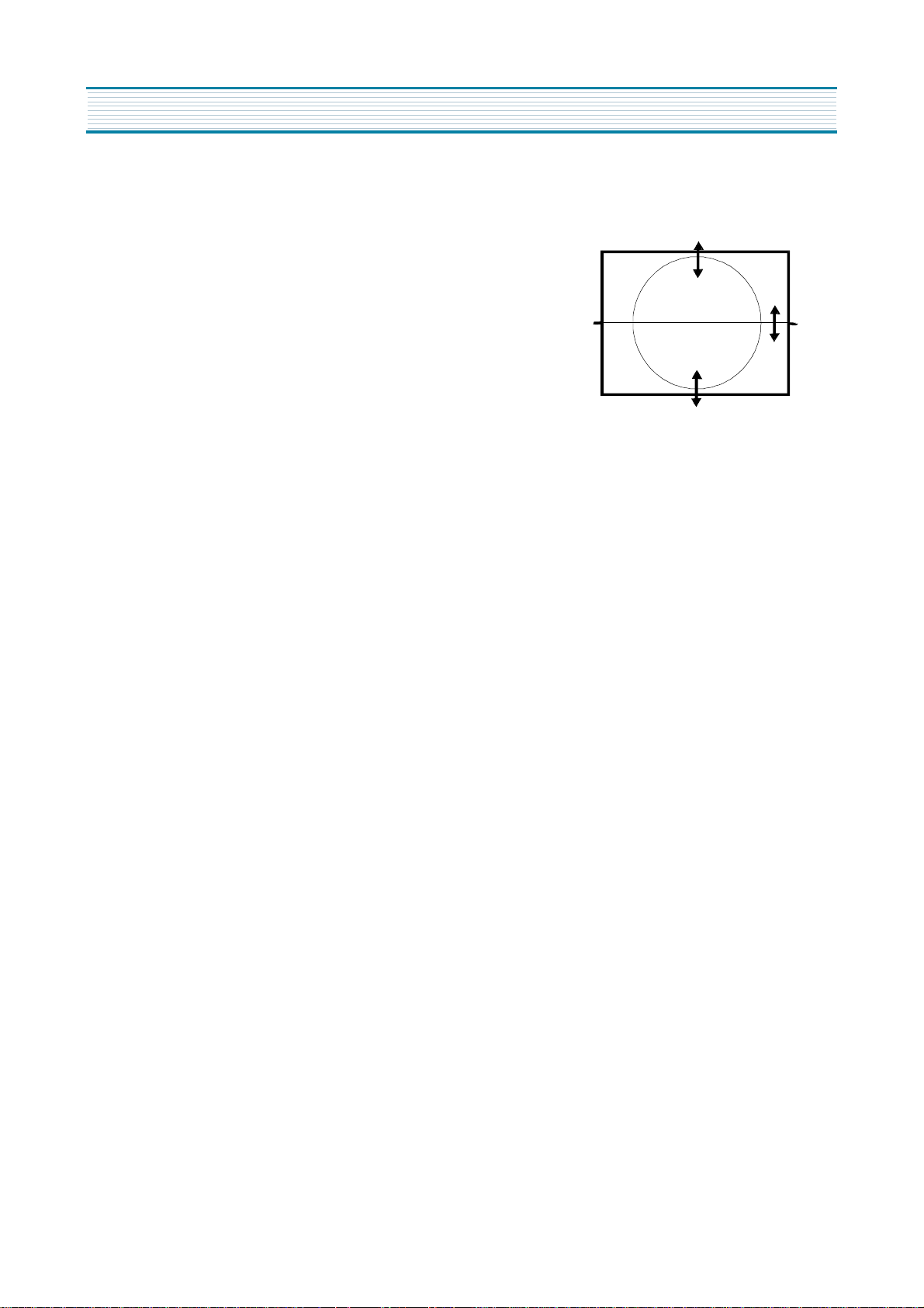
3 - Focus
- Adjust the Focus volume ( on FBT ) to have the best resolution on screen.
4 - Vertical geometry
- Adjust the Vertical Amplitude, Shift, S-Correction and Slope
to compensate for vertical distortion
5 - Horizontal picture centering
- Adjust H Shift to have the picture in the center of the screen.
7 - AGC
- Adjust the antenna signal level to 70 dB
µ
V
±
2 for Daewoo tuner (62 dB
µ
V
±
2 for Philips tuner).
- Set RF AGC to 0.
- Increase RF AGC level and stop when the level on pin 6 of I501 goes below 2.5 Vdc
ALIGNMENT INSTRUCTIONS
AUDIO
VIDEO
11
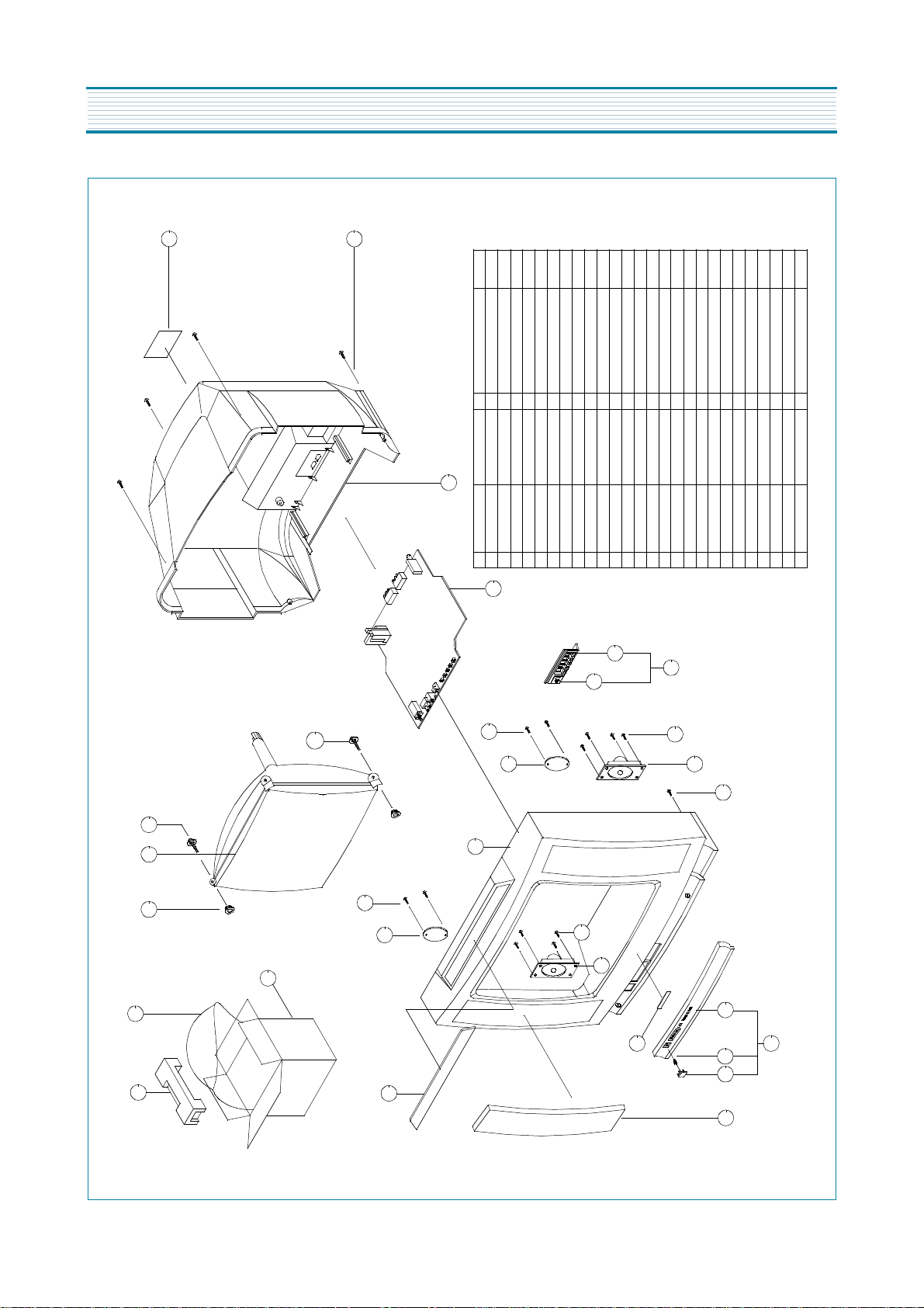
EXPLODED VIEW
20
19
EPS 20D51PAD
4858193401
LDPE T0.03X1300X1000
1
BAG PE
4858211800
DW-3
1
CARTON BOX
4858055200
150 ART P/E FILM(C/TV)1SPEC PLATE
4855415800
HIPS BK
4852155601
4856214902
30X190 BK2
SCREW CRT FIXING AS
30X80 BK
2SCREW CRT FIXING AS
4856013300
PVC T1.0
4857618000
TT2 WAS 3X12 MFZN BK
SCREW TAPPTIE
TT2 WAS 3X12 MFZN BK
2
SCREW TAPPTIE
7128301212
CUAU+ABS BK
1
MARK BRAND
4855617500
20
19
18
14-3
14-2
17
16
15
14
10-1
10
10-1
9-1
9-1
4-1
9
8
7
5
10
6
14-1
13
12
9
PC BK
1
4856013302
2
1
CR T2.0
4856215402
1
5 TT2 TRS 4X14 MFZN BK
7172401412
4
1
1
1
4945801+5541201
4851915401
HIPS BK
4854945801
1
1
11
1
1
2
8
7128301212
1
HIPS BK
4852073601
HIPS BK
4852326511
1
SWPA PIE 0.5
4856716000
ABS BK
2326511+4856401+6716000
PMMA MILKY
EGI T0.5
18
17
16-1
4855313101
4855541201
4852067101
4854856401
4852539601
16-1
16
15
14-3
14-2
14-1
14
13
12
11
10
9-1
9
8
7
6
5
4-1
4
3
2
1
COVER BACK
SCREW TAPPTITE
RUBBER
CRT
BUTTON CTRL
BUTTON
DECO SENSOR
INSU PLATE
SPEAKER
MASK FRONT
DECO COVER
PANEL FRONT
PANEL
SPRING
BUTTON POWER
GRILL
11
4
3
2
1
MATERIAL
REMARK S
MAIN PCB
PART NAME Q'tyPART CODENo

12
PRINTED CIRCUIT BOARD
13
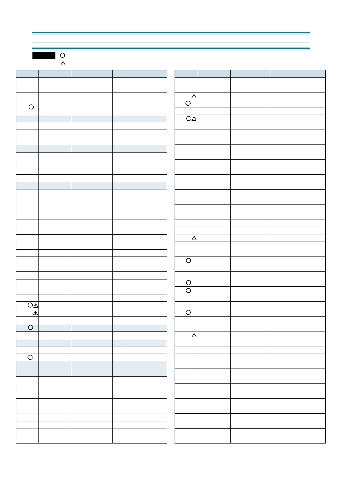
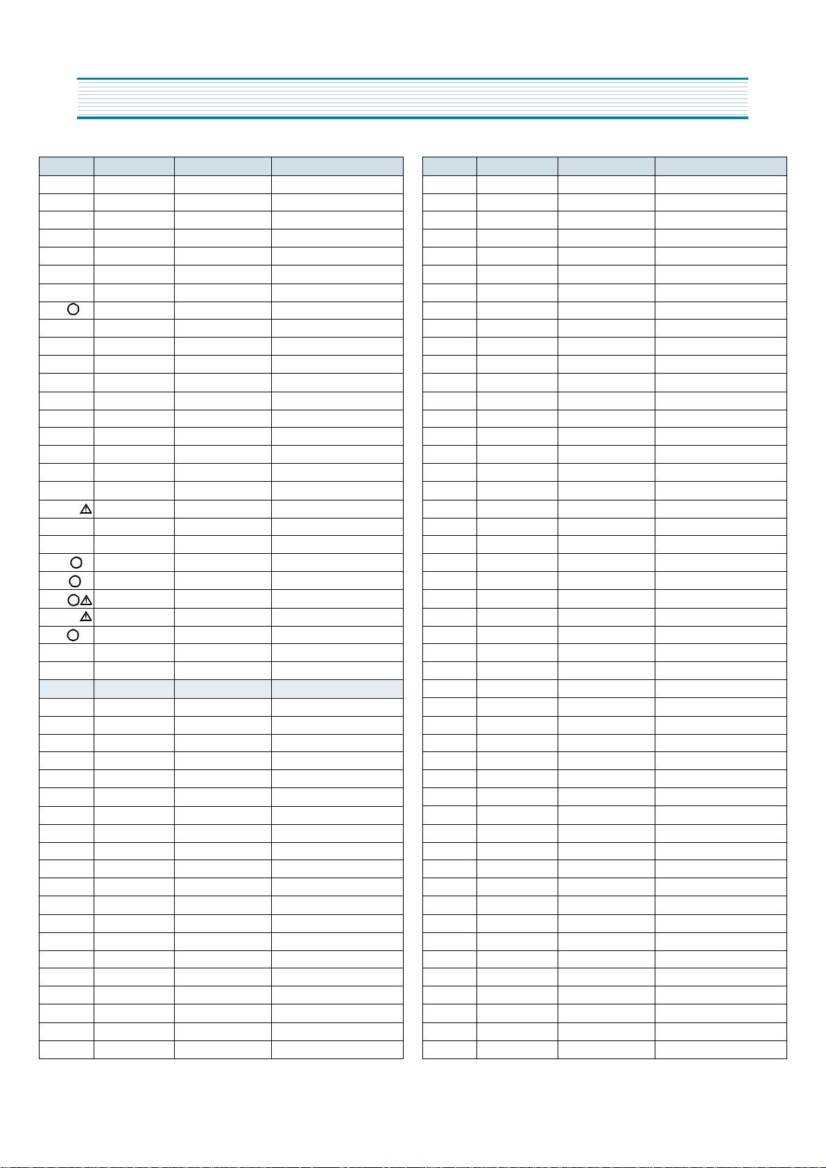
SERVICE PARTS LIST
LOC. PART CODE PART NAME PART DESCRIPTION
ZZ110 PTACPWA21C6A ACCESSORY AS DTA-21C6TAF
00100 4850Q00910P BATTERY DAEWOO AAA
M821 4858213800 BAG POLY L.D.P.E.T0.5X250X40 MILK
ZZ100 48B3740A01
TRANSMITTER
R-40A01
REMOCON
ZZ120 PTBCSHD616 COVER BACK AS DTP-21C6TFP
M211 4852151601 COVER BACK HIPS BK 21V1, V4, C6
M541 4855415800 S/PLATE 150ART P/E FILM (C/TV)
M542 4855800022 LABEL SERIAL ART 90 70X19
ZZ130 PTPKCPA21C6A PACKING AS DTA-21C6TAF
10 6520010200 STAPLE PIN #3417 ALL
20 6520010200 STAPLE PIN #3417 ALL
M811 4858190700 PAD EPS 21C6
M821 4858211801 BAG P.E. PE FILM T0.05X1300X1000
ZZ140 PTCACAA21C6AF CABINET AS DTA-21C6TAF
M191 4854943202 BUTTON CONTROL 21C6
M201A 4856013301
SCREW CRT FIXING
L-140
AS
M201B 4856215402 WASHER RUBBER 20''
M201C 4856013303
SCREW CRT FIXING
L-240
AS
M211A 7172401412 SCREW TAPPING TT2 TRS 4X14 MFZN BK
M211D 7172401412 SCREW TAPPING TT2 TRS 4X14 MFZN BK
M481 4854943203 BUTTON POWER ABS BK 21C6
M551 4855538000 DECO SENSOR 21C6
M561 485562140101 MARK BRAND DAEWOO 14/20/21/C4/C6
M681 4856812001 TIE CABLE NYLON66 DA100
P402A 4850706N06 CONN AS 35135-0620+35719+ULW=550
PWC1 4859906210 CORD POWER FTZ (LOMAX NEW TYPE)
SP01A 7178301011 SCREW TAPPING TT2 WAS 3X10 MFZN
V901 4859607660C CRT (PHILIPS 21") A51EAL155X17 (CONN AS)
ZZ131 58G0000074 COIL DEGAUSSING 21" DC-2070
ZZ132 48519A5310 CRT GROUND AS 2101S-1015-1P
ZZ200 PTFMSJD616 MASK FRONT AS DTP-21C6TFP
M201 4852071401 MASK FRONT HIPS BK 21C6
ZZ210 PTSPPWA615 SPEAKER AS DTP-14C4TFD
P601A 4850703S50 CONN AS YH025-03+3509=200
SP01 4858314010 SPEAKER SP-5070F01 3W 8 OHM
ZZ290 PTMPMSA21C6AF
PCB MAIN MANUAL
DTA-21C6TAF
AS
10 2193100801 SOLDER BAR SN:PB=63:37 3PI(NO FLUX)
40 2291050314 FLUX SOLVENT IM-1000
20 2193011101 SOLDER WIRE RS 60-1.2 1.6A
30 2291050617P FLUX SOLDER CF-329D
50 2291140501 WAX COVER 60G/PC
60 2291051001 FLUX KILLER KFT-7
C315 CEXF2C470C C ELECTRO 160V RUS 47MF (13X25) TP
C404 CMYT3C822J C MYLAR 1.6KV 8200PF MKP
C408 CMYE2D364J C MYLAR 200V 0.36MF J (PL)
R
is a recommendable part for stock.
is safety component, so it must be used the same component.
Caution
R
C415 CEXF2E100V C ELECTRO 250V RSS 10MF (10X20) TP
C603 CEXF1C471V C ELECTRO 16V RSS 470MF (10X12.5)TP
C801 CL1SC3474M C LINE ACROSS 275V 0.47MF
C805 CEYN2G121P C ELECTRO 400V LHS 120MF
C810 CCXB3D102K C CERA 2KV B 1000 PF K (TAPPING)
C812 CH1AFE472M C CERA AC 4KV 4700PF M KX DE1610
C813 CEXF2C101V C ELECTRO 160V RSS 100MF (16X25) TP
C814 CEXF2C101V C ELECTRO 160V RSS 100MF (16X25) TP
C820 CCXB3A471K C CERA 1KV B 470PF K (T)
C823 CEXF1E102V C ELECTRO 25V RSS 1000MF (13X20) TP
C824 CCXB3A471K C CERA 1KV B 470PF K (T)
C831 CCXB3A471K C CERA 1KV B 470PF K (T)
C832 CEXF1E102V C ELECTRO 25V RSS 1000MF (13X20) TP
C840 CEXF1C222V C ELECTRO 16V RSS 2200MF(13X25)TP
C841 CEXF1C222V C ELECTRO 16V RSS 2200MF(13X25)TP
C861 CEXF1E102V C ELECTRO 25V RSS 1000MF (13X20) TP
C866 CCXB3A471K C CERA 1KV B 470PF K (T)
C965 CCXB3D102K C CERA 2KV B 1000 PF K (TAPPING)
D403 DBY228---- DIODE BY228
D707 DSML1216W- LED SML1216W
D820 DBYW76---- DIODE BYW76
F801 5FSCB4022R FUSE CERA SEMKO F4AH 4A 250V MF51
G900 4SG0D00103 SPARK GAP S-23 900V-1.5KV
I101 1TDA9830-- IC RF TDA9830
I301 1TDA8357J- IC VERTICAL TDA8357J
I301A 4857025405 HEAT SINK A1050P-H24 (CP-185)
I301B 7174301011 SCREW TAPPTITE TT2 RND 3X10 MFZN
I501 1TDA9361-- IC MAIN TDA9361PS/N1/3
I601 1TDA7267A- IC AMP TDA7267A
I702 1AT24C08PC IC MEMORY AT24C08-10PC
I703 1KRT30---- IC PREAMP KRT30
I801 1STRF6653- IC SMPS STR-F6653
I801A 4857024618 HEAT SINK I801A (CP-385 AIWA)
I801B 7174300811 SCREW TAPPTITE TT2 RND 3X8 MFZN
I804 1LTV817C-- IC PHOTO COUPLER LTV-817C
I806 1SE110N--- IC SE110N
I810 TX0202DA-- THYRISTOR X0202DA
I820 1KA7805--- IC REGULATOR KA7805
I822 1KA7808--- IC REGULATOR KA7808
I823 1LE33CZ--- IC REGULATOR LE33CZ
I901 1TDA6107Q- IC VIDEO TDA6107Q
I901A 4857031100 HEAT SINK A1050P-H24 T2.0
I901B 7174301011 SCREW TAPPTITE TT2 RND 3X10 MFZN
JPA1 4859200401 SOCKET RGB SR-21A1 (ANGLE TYPE)
JS1 4859109950 JACK PIN BOARD PH-JB-9710A
L401 58H0000016 COIL H-LINEARITY L-102 (102UH)
L802 58C9430599 COIL CHOKE AZ-9004Y(94MH)
LF801 5PLF24A1-- FILTER LINE LF-24A1
M351 4853533600 HOLDER LED P.P BK
LOC. PART CODE PART NAME PART DESCRIPTION
R
R
R
R
R
R
R
R
R
14
M791 4857913304 RUBBER CUSION FR RUBBER SPONGE
P401 4850705N18 CONN AS BIC-05T-25T+ULW=400
P402 4859240120 CONN WAFER YFW500-06
P501 4850705N14 CONNECTOR BIC-05T-25T+ULW=500
P601 4859231620 CONN WAFER YW025-03
P801 4859287320 CONN WAFER MKS2822 (LOMAX NEW TYPE)
P802 4859242220 CONN WAFER YFW800-02
Q401 T2SD2499-- TR 2SD2499
R305 RS02Y331JS R M-OXIDE FILM 2W 330 OHM J SMALL
R415 RS02Y102JS R M-OXIDE FILM 2W 1K OHM J SMALL
R450 RS02Y103JS R M-OXIDE FILM 2W 10K OHM J SMALL
R801 DT120B8010 POSISTOR T120-B80-A110
R802 RS02Y753JS R M-OXIDE FILM 2W 75K OHM J SMALL
R803 RS02Y473JS R M-OXIDE FILM 2W 47K OHM J SMALL
R804 RF02Y338K- R FUSIBLE 2W 0.33 OHM K
R808 RS02Y821JS R M-OXIDE FILM 2W 820 OHM J SMALL
R819 RX07C339JF R CEMENT 7W 3.3 OHM J 15MM 4P
R920 RF01Y209JA R FUSIBLE 1W 2 OHM J A CURVE
SCT1 4859303530 SOCKET CRT PCS629-03C
SF1 5PG1984M-- FILTER SAW G1984M
SF2 5PL9653M-- FILTER SAW L9653M
SW801 5S40101146 SW POWER PUSH SS-160-7-B
T401 50D10A2--- TRANS DRIVE TD-10A2
T402 50H0000211 FBT 1142.5109
T801 20745046-- TRANS SMPS 2074.5046
U100 4859720730 TUNER VARACTOR UV1316/A
X502 5XE12R000E CRYSTAL QUARTZ HC-49/U 12.00000MHZ 30PPM
Z501 5PXPS5R5MB FILTER CERA TPS5.5MB-TF21 TAPING
ZZ200 PTMPJRA21C6AF PCB MAIN RADIAL AS DTA-21C6TAF
C101 CEXF1H100V C ELECTRO 50V RSS 10MF (5X11) TP
C102 CEXF1H470V C ELECTRO 50V RSS 47MF (6.3*11) TP
C106 CEXF1E221V C ELECTRO 25V RSS 220MF (8X11.5) TP
C120 CCXB1H102K C CERA 50V B 1000PF K (TAPPING)
C121 CEXF1H100V C ELECTRO 50V RSS 10MF (5X11) TP
C152 CEXF1H229V C ELECTRO 50V RSS 2.2MF (5X11) TP
C153 CBXF1H104Z C CERA SEMI 50V F 0.1MF Z (TAPPING)
C154 CEXF1H479V C ELECTRO 50V RSS 4.7MF (5*11) TP
C155 CEXF1H479V C ELECTRO 50V RSS 4.7MF (5*11) TP
C156 CEXF1H479V C ELECTRO 50V RSS 4.7MF (5*11) TP
C305 CEXF1E221V C ELECTRO 25V RSS 220MF (8X11.5) TP
C313 CBXF1H104Z C CERA SEMI 50V F 0.1MF Z (TAPPING)
C320 CBXF1H104Z C CERA SEMI 50V F 0.1MF Z (TAPPING)
C390 CMXM2A473J C MYLAR 100V 0.047MF J TP
C401 CEXF1H470V C ELECTRO 50V RSS 47MF (6.3*11) TP
C412 CEXF2C339V C ELECTRO 160V RSS 3.3MF (8X16) TP
C414 CMXM2A104J C MYLAR 100V 0.1MF J TP
C417 CMXL2E104K C MYLAR 250V 0.1MF K MEU TP
C418 CCXB1H102K C CERA 50V B 1000PF K (TAPPING)
C420 CCXB2H222K C CERA 500V B 2200PF K (TAPPING)
LOC. PART CODE PART NAME PART DESCRIPTION
SERVICE PARTS LIST
R
R
R
C500 CEXF1H478V C ELECTRO 50V RSS 0.47MF (5X11) TP
C501 CEXF1H100V C ELECTRO 50V RSS 10MF (5X11) TP
C502 CEXF1H100V C ELECTRO 50V RSS 10MF (5X11) TP
C504 CMXM2A332J C MYLAR 100V 3300PF J TP
C509 CEXF1E470V C ELECTRO 25V RSS 47MF (5X11) TP
C511 CMXB1H224J C MYLAR 50V EU 0.22MF J(TP)
C512 CMXB1H224J C MYLAR 50V EU 0.22MF J(TP)
C513 CBXF1H104Z C CERA SEMI 50V F 0.1MF Z (TAPPING)
C514 CEXF1E101V C ELECTRO 25V RSS 100MF (6.3X11) TP
C517 CEXF1H109V C ELECTRO 50V RSS 1MF (5X11) TP
C519 CEXF1H229V C ELECTRO 50V RSS 2.2MF (5X11) TP
C522 CEXF1H479V C ELECTRO 50V RSS 4.7MF (5*11) TP
C524 CMXB1H104J C MYLAR 50V EU 0.1MF J (TP)
C525 CCXB1H102K C CERA 50V B 1000PF K (TAPPING)
C526 CMXB1H104J C MYLAR 50V EU 0.1MF J (TP)
C527 CMXM2A473J C MYLAR 100V 0.047MF J TP
C528 CEXF1E101V C ELECTRO 25V RSS 100MF (6.3X11) TP
C530 CEXF1C101V C ELECTRO 16V RSS 100MF (6.3X11) TP
C532 CEXF1H100V C ELECTRO 50V RSS 10MF (5X11) TP
C533 CCXB1H102K C CERA 50V B 1000PF K (TAPPING)
C537 CBXF1H104Z C CERA SEMI 50V F 0.1MF Z (TAPPING)
C555 CEXF1C470V C ELECTRO 16V RSS 47MF (5X11) TP
C560 CBXF1H104Z C CERA SEMI 50V F 0.1MF Z (TAPPING)
C564 CEXF1E101V C ELECTRO 25V RSS 100MF (6.3X11) TP
C565 CBXF1H104Z C CERA SEMI 50V F 0.1MF Z (TAPPING)
C570 CCXB1H472K C CERA 50V B 4700PF K (TAPPING)
C571 CCXB1H821K C CERA 50V B 820PF K (TAPPING)
C585 CCXB1H222K C CERA 50V B 2200PF K (TAPPING)
C590 CXCH1H270J C CERA 50V CH 27PF J (TAPPING)
C591 CXCH1H270J C CERA 50V CH 27PF J (TAPPING)
C592 CBXF1H104Z C CERA SEMI 50V F 0.1MF Z (TAPPING)
C593 CEXF1E101V C ELECTRO 25V RSS 100MF (6.3X11) TP
C599 CEXF1H229V C ELECTRO 50V RSS 2.2MF (5X11) TP
C600 CEXF1E101V C ELECTRO 25V RSS 100MF (6.3X11) TP
C601 CEXF1H108V C ELECTRO 50V RSS 0.1MF (5X11) TP
C602 CCXF1H103Z C CERA 50V F 0.01MF Z (TAPPING)
C650 CEXF1E470V C ELECTRO 25V RSS 47MF (5X11) TP
C770 CEXF1C101V C ELECTRO 16V RSS 100MF (6.3X11) TP
C803 CCXF3A472Z C CERA 1KV F 4700PF Z (T)
C804 CCXF3A472Z C CERA 1KV F 4700PF Z (T)
C806 CEXF1H330V C ELECTRO 50V RSS 33MF (6.3X11) TP
C807 CCXF1H473Z C CERA 50V F 0.047MF Z (TAPPING)
C808 CEXF1H479V C ELECTRO 50V RSS 4.7MF (5*11) TP
C821 CCXB1H102K C CERA 50V B 1000PF K (TAPPING)
C835 CEXF1H470V C ELECTRO 50V RSS 47MF (6.3*11) TP
C844 CEXF1E101V C ELECTRO 25V RSS 100MF (6.3X11) TP
C863 CEXF1E101V C ELECTRO 25V RSS 100MF (6.3X11) TP
C888 CEXF1C470V C ELECTRO 16V RSS 47MF (5X11) TP
C910 CCXB1H152K C CERA 50V B 1500PF K (TAPPING)
LOC. PART CODE PART NAME PART DESCRIPTION
R
R
 Loading...