


Daewoo D1146, D1146, D1146TI, DE08TIS, D1146TI Service Manual
...65.99897-8056 Feb. 2001
MAINTENANCE MANUAL
Diesel Engine
D1146
D1146TI
DE08TIS
PS-MMA0415-E1A
D1146/D1146TI/DE08TIS
MAINTENANCE MANUAL
FOREWORD
This maintenance manual is designed to serve as a reference for DAEWOO Heavy Industries Ltd's (here after DAEWOO’s) customers and distributors who wish to gain basic product knowledge on DAEWOO's D1146, D1146TI and DE08TIS Diesel engine.
This economical and high-performance diesel engine (6 cylinders, 4 strokes, in-line, direct injection type) has been so designed and manufactured to be used for the overland transport or industrial purpose. That meets all the requirements such as low noise, fuel economy, high engine speed, and durability.
To maintain the engine in optimum condition and retain maximum performance for a long time, CORRECT OPERATION and PROPER MAINTENANCE are essential.
In this manual, the following symbols are used to indicate the type of service operations to be performed.
Removal |
Adjustment |
Installation |
Cleaning |
Disassembly |
Pay close attention-Important |
Reassembly |
Tighten to specified torque |
Align the marks |
Use special tools of manufacturer's |
Directional Indication |
Lubricate with oil |
Inspection |
Lubricate with grease |
Measurement |
|
During engine maintenance, please observe following instructions to prevent environmental damage;
zTake old oil to an old oil disposal point only.
zEnsure without fail that oil and diesel fuel will not get into the sea or rivers and canals or the ground.
zTreat undiluted anti-corrosion agents, antifreeze agents, filter element and cartridges as special waste.
Printed in Jan. 2001 PS-MMA0415-E1A

D1146/D1146TI/DE08TIS
MAINTENANCE MANUAL
zThe regulations of the relevant local authorities are to be observed for the disposal of spent coolants and special waste.
If you have any question or recommendation in connection with this manual, please do not hesitate to contact our head office, dealers or authorized service shops near by your location for any services.
For the last, the content of this maintenance instruction may be changed without notice for some quality improvement. Thank you.
DAEWOO Heavy Industries & Machinery LTD.
Feb. 2001
Printed in Jan. 2001 PS-MMA0415-E1A

D1146/D1146TI/DE08TIS
MAINTENANCE MANUAL
CONTENTS |
|
1. GENERAL INFORMATION |
|
1.1 General Repair Instructions |
1 |
1.2. Engine Specific Character |
2 |
1.3. Engine Specifications |
4 |
1.4. Engine Assembly |
8 |
2. MAJOR MAINTENANCE |
|
2.1. Preventive Maintenance |
13 |
2.2. Diagnosis and Remedy |
22 |
2.3. Engine Inspection |
32 |
3. MAINTENANCE |
|
3.1. Engine Disassembly |
33 |
3.2. Inspection and Measurement on Major Parts |
48 |
3.3. Reassembly |
69 |
3.4. Breaking in |
96 |
4. MAINTENANCE OF MAJOR COMPONENTS |
|
4.1. Cooling System |
98 |
4.2. Lubrication System |
102 |
4.3. Fuel Injection Pump |
106 |
4.4. Turbocharger |
122 |
5. Special Tool List |
132 |
● Appendix |
134 |
● WORLDWIDE NETWORK |
|
Printed in Jan. 2001 PS-MMA0415-E1A

D1146/D1146TI/DE08TIS
MAINTENANCE MANUAL
1. GENERAL INFORMATION
1.1.General Repair Instructions
1.Before performing service operation, disconnect the grounding cable from the battery for reducing the chance of cable damage and burning due to short-circuiting.
2.Use covers for preventing the components from damage or pollution.
3.Engine oil and anti-freeze solution must be handled with reasonable care as they cause paint damage.
4.The use of proper tools and special tools where specified is important to efficient and reliable service operation.
5.Use genuine DAEWOO parts necessarily.
6.Used cotter pins, gaskets, O-rings, oil seals, lock washer and self-lock nuts should be discarded and new ones should be prepared for installation as normal function of the parts can not be maintained if these parts are reused.
7.To facilitate proper and smooth reassemble operation, keep disassembled parts neatly in groups. Keeping fixing bolts and nut separate is very important as they vary in hardness and design depending on position of installation.
8.Clean the parts before inspection or reassembly. Also clean oil ports, etc. using compressed air to make certain they are free from restrictions.
9.Lubricate rotating and sliding faces of parts with oil or grease before installation.
10.When necessary, use a sealer on gaskets to prevent leakage.
11.Carefully observe all specifications for bolts and nuts torques.
12.When service operation is completed, make a final check to be sure service has been done property.
1
Printed in Jan. 2001 PS-MMA0415-E1A
D1146/D1146TI/DE08TIS
MAINTENANCE MANUAL
1.2. Engine Specific Character
1.2.1.Toroidal combustion mode (D1146)
The D1146 engine is operated in the toroidal combustion mode that was developed by this company with AVL Co. Australia.
The feature of this mode in the fundamental structure is that there are combustion chambers in the centers of piston heads and swirling passages in the cylinder heads. This swirling passages when intake stroke generates the strong swirling motion in the combustion chambers by giving the intake air a big moment, and when compression stroke, the special piston’s shapes causing very complicated and distorted flows by means of eddy current and squashed flows will make the air and fuel mix more smoothly.
Also, when explosion stroke, a considerable output increase came to be expected with the accomplishment of nearly perfect combustion by the more smooth mixing of air and fuel which was injected through multi-nozzles in the combustion chamber.
This engine by means of Toroidal Combustion Mode has the specific character such as quiet and stable revolutional motion, multi-purpose application, economical fuel and oil consumption, etc.
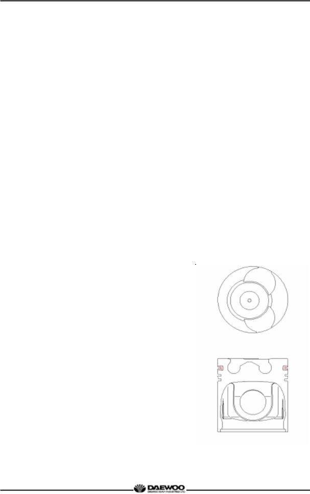
1.2.2.OMEGA combustion bowl (D1146TI, DE08TIS)
The OMEGA combustion bowl is a unit designed |
M1041A |
|
to perform high efficiency, low emission |
|
|
combustion. As the rim around the combustion |
|
|
bowl port of the upper of the piston has been |
|
|
machined in a smaller size than the interior of the |
|
|
combustion bowl, strong swirl is produced in the |
|
|
combustion bowl and strong squish flow makes |
|
|
the fuel be mixed more sufficiently with air. |
|
|
Due to the application of OMEGA combustion |
|
|
system and optimal utilization of intake and |
|
|
exhaust port configuration within the cylinder |
|
|
head, the D1146TI, DE08TIS diesel engines |
|
|
discharge very low level of hazardous exhaust |
|
|
gases such as smoke, nitrogen oxide, |
|
|
hydrocarbon, or carbon monoxide and thus |
|
|
ensure high performance and low fuel |
|
|
consumption. |
|
|
2 |
|
|
Printed in Jan. 2001 PS-MMA0415-E1A
D1146/D1146TI/DE08TIS
MAINTENANCE MANUAL
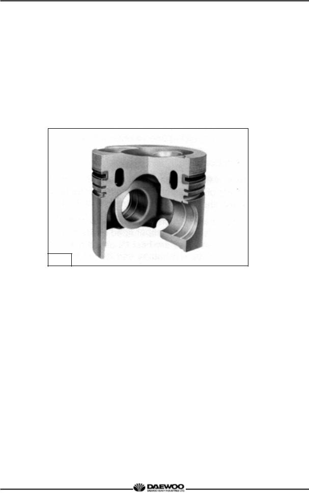
1.2.3.Oil gallery cooling type piston (DE08TIS)
Oil gallery cooling is used for the piston of DE08TIS diesel engine.
When thermal loading is high, piston cooling by means of an oil gallery in the crown is normally necessary to prevent crown cracking and ring sticking. The design of the gallery, the design and location of the oil spray nozzle and the quantity of oil flowing in the gallery are critical in order to achieve the desired temperature reduction.
The cross section shape of the gallery should be designed to achieve sufficient oil movement to maximize cooling efficiency.
M1255
3
Printed in Jan. 2001 PS-MMA0415-E1A

D1146/D1146TI/DE08TIS
MAINTENANCE MANUAL
1.3. Engine Specifications
1.3.1. Specification
|
Engine Model |
D1146 |
|
D1146TI |
|
DE08TIS |
||
Items |
|
|
|
|||||
|
|
|
|
|
|
|
||
|
|
|
|
|
|
|
|
|
Engine type |
|
4 cycle in-line, |
|
|
4 cycle |
in-line, |
||
|
Water-cooled type |
|
|
Water-cooled type |
||||
|
|
|
Naturally aspirated |
|
Turbo charged & intercooled |
|||
Combustion chamber type |
|
|
|
Direct injection type |
|
|
||
|
|
|
|
|
|
|
||
Cylinder liner type |
|
|
Replaceable dry liner |
|
||||
|
|
|
|
|
|
|
|
|
Timing gear system |
|
|
|
Gear driven type |
|
|
||
|
|
|
|
|
||||
No. of piston ring |
|
Compression ring 2, oil ring 1 |
||||||
|
|
|
|
|
|
|
|
|
No. of cylinder-bore x stroke |
(mm) |
|
|
6 – 111 × 139 |
|
|
||
|
|
|
|
|
|
|
|
|
Total piston displacement |
(cc) |
|
8,071 |
|
|
|||
|
|
|
|
|
|
|
|
|
Compression ratio |
|
17.5 : 1 |
|
16.8 : 1 |
|
18.5 : 1 |
||
|
|
|
|
|
|
|
|
|
Engine dimension (length x width x height) |
(mm) |
1,253x811.5x934.5 |
|
1,253x812.5x1,009 |
1,253x812.5x1,009 |
|||
|
|
|
|
|
|
|
|
|
Engine weight |
(kg) |
730 |
|
745 |
|
745 |
||
|
|
|
|
|
|
|
|
|
Rotating direction (viewed from flywheel) |
|
|
|
Counter clockwise |
|
|
||
|
|
|
|
|
|
|
||
Fuel injection order |
|
|
1 – 5 – 3 – 6 – 2 – 4 |
|
||||
|
|
|
|
|
|
|
|
|
Fuel injection timing (B.T.D.C static) |
|
15° |
|
9° |
|
3° |
||
|
|
|
|
|
|
|
|
|
Injection pump type |
|
Zexel in-line “AD” type |
|
Zexel in-line “P” type |
||||
|
|
|
|
|
|
|
|
|
Governor type |
|
Mechanical governor |
|
Mechanical |
||||
|
|
governor |
||||||
|
type(RLD) |
|
||||||
|
|
|
|
type(RLD-J) |
||||
|
|
|
|
|
|
|
|
|
Injection nozzle type |
|
Multi-hole type (5 hole) |
|
Multi-hole type |
||||
|
|
(7 hole) |
||||||
|
|
|
|
|
|
|
|
|
Fuel injection pressure |
(kg/cm2) |
210 |
|
214 |
|
160/220 |
||
Compression pressure |
(kg/cm2) |
|
|
28 (at 200 rpm) |
|
|
||
Intake and exhaust valve clearance (at cold) (mm) |
|
0.3 |
|
|
||||
|
|
|
|
|
|
|
|
|
Intake valve |
Open at |
|
|
|
16° (B.T.D.C) |
|
|
|
|
|
|
|
|
|
|
|
|
Close at |
|
|
|
36° (A.B.D.C) |
|
|
||
|
|
|
|
|
|
|||
|
|
|
|
|
|
|
|
|
Exhaust valve |
Open at |
|
|
|
46° (B.B.D.C) |
|
|
|
|
|
|
|
|
|
|
|
|
Close at |
|
|
|
14° (A.T.D.C) |
|
|
||
|
|
|
|
|
|
|||
|
|
|
|
|
||||
Lubrication method |
|
Full forced pressure feed type |
||||||
|
|
|
|
|||||
Oil pump type |
|
Gear type driven by crankshaft |
||||||
|
|
|
|
|
||||
Oil filter type |
|
Paper element type |
|
Cartridge type |
||||
|
|
|
|
|
|
|
|
|
Lubricating oil capacity (max./min.) |
(lit) |
|
|
15.5/12 or 20/17 |
|
|
||
|
|
|
|
|
|
|
||
Oil cooler type |
|
|
|
Water cooled |
|
|
||
|
|
|
||||||
Water pump |
|
Centrifugal type driven by belt |
||||||
|
|
|
||||||
Cooling Method |
|
Fresh water forced circulation |
||||||
|
|
|
|
|
|
|||
Cooling water capacity (engine only) |
(lit) |
|
14 |
|
|
|||
|
|
|
|
|
|
|
|
|
Thermostat type |
|
|
|
Wax pallet type |
|
|
||
|
(79 94 °C or 83 95 °C ) |
|||||||
|
|
|
||||||
Air compressor type & capacity |
(cc) |
Belt driven type, 220 or 300 |
||||||
|
|
|
|
|
|
|
||
Alternator voltage – capacity |
(V – A) |
|
|
24 – 45 or 24-150 |
|
|
||
|
|
|
|
|
|
|
||
Starting Motor voltage – output |
(V - kW) |
|
|
24 – 4.5 |
|
|
||
|
|
|
|
|
|
|
||
Air heater capacity |
(V – A) |
|
|
22 – 95 (2.1kW) |
|
|
||
|
|
|
|
|
|
|||
Battery capacity |
(V - AH) |
|
24 - 150 |
|
|
|||
|
|
|
|
|
|
|
|
|
|
|
|
4 |
|
|
|
|
|
Printed in Jan. 2001 PS-MMA0415-E1A

D1146/D1146TI/DE08TIS
MAINTENANCE MANUAL
1.3.2. Engine power
Production tolerance : ±5%
Engine model |
|
|
Performance |
|
|
|||
|
|
|
|
|
|
|
|
|
|
|
Injection |
Power |
Torque |
Low idle |
High idle |
|
|
Model |
Suffix |
timing |
Remark |
|||||
(PS/rpm) |
(kg.m/rpm) |
(rpm) |
(rpm) |
|||||
|
|
(BTDC°) |
|
|||||
|
EACBA |
|
|
|
|
|
|
|
|
EACBB |
|
|
|
|
|
|
|
D1146 |
EACBE |
15 |
182/2,500 |
57.5/1,600 |
600-650 |
2750 |
|
|
EACBH |
|
|||||||
|
|
|
|
|
|
|
||
|
EACBI |
|
|
|
|
|
|
|
|
EACBK |
|
|
|
|
|
|
|
|
|
|
|
|
|
|
|
|
|
|
|
|
|
|
2370 |
|
|
|
EAPBA |
9 |
205/2,200 |
75/1,400 |
600-650 |
- |
|
|
|
|
|
|
|
|
2,470 |
|
|
D1146TI |
|
|
|
|
|
|
EURO-I |
|
|
|
|
|
|
2250 |
|||
|
|
|
|
|
|
|
||
|
EAPCA |
9 |
215/2,300 |
82/1,400 |
600-650 |
- |
|
|
|
|
|
|
|
|
2,350 |
|
|
|
|
|
|
|
|
|
|
|
|
ECPBA |
3 |
225/2,300 |
82/1,200 |
600-650 |
2,530 |
|
|
|
ECPCA |
|
||||||
|
|
|
|
|
|
|
||
DE08TIS |
|
|
|
|
|
|
EURO-II |
|
ECPBB |
3 |
240/2,300 |
90/1,200 |
600-650 |
2,530 |
|||
|
|
|||||||
|
ECPCB |
|
||||||
|
|
|
|
|
|
|
||
|
|
|
|
|
|
|
|
|
* Note : All data are based on operation without cooling fan at ISO 1585(SAE J1349).
5
Printed in Jan. 2001 PS-MMA0415-E1A
D1146/D1146TI/DE08TIS |
MAINTENANCE MANUAL |
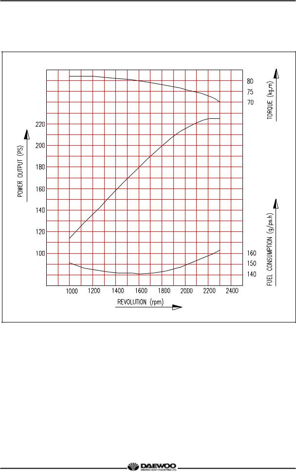
1.3.3. Performance curve (DE08TIS – 225PS) |
Performance |
|
ISO 1585(SAE J1349) |
|
|
|
Output |
(max.) |
165 kW (225PS) / 2,300 rpm |
|
|
|
Torque |
(min) |
804 N.m (82 kg.m) / 1,200 rpm |
|
|
|
Fuel consumption |
(min) |
192 g/kW.h (141 g / PS.h) |
|
|
|
6
Printed in Jan. 2001 PS-MMA0415-E1A
D1146/D1146TI/DE08TIS |
MAINTENANCE MANUAL |
1.3.4. Performance curve (DE08TIS – 240PS) |
Performance |
|
ISO 1585(SAE J1349) |
|
|
|
Output |
(max.) |
176 kW (240PS) / 2,300 rpm |
|
|
|
Torque |
(max.) |
882 N.m (90 kg.m) / 1,200 rpm |
|
|
|
Fuel consumption |
(min.) |
192 g/kW.h (141 g / PS.h) |
|
|
|
7
Printed in Jan. 2001 PS-MMA0415-E1A

D1146/D1146TI/DE08TIS
MAINTENANCE MANUAL
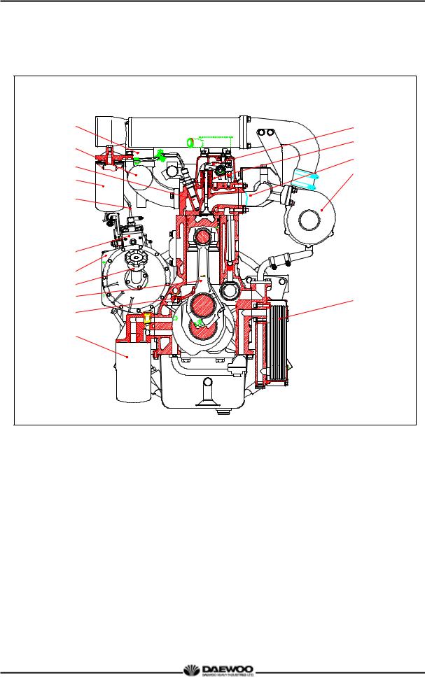
1.4. Engine Assembly
1.4.1. Engine sectional view (longitudinal)
|
4 |
5 |
|
|
|
|
|
|
6 |
3 |
|
|
|
7 |
|
|
|
|
|
|
|
|
|
8 |
2 |
|
|
|
9 |
|
|
|
|
|
1 |
|
|
|
10 |
|
|
|
|
11 |
|
|
|
|
12 |
|
|
|
|
13 |
|
|
|
|
14 |
19 |
|
|
|
15 |
|
|
|
|
16 |
|
|
|
|
17 |
20 |
|
|
|
18 |
|
|
|
|
|
21 |
|
|
|
|
22 |
23 |
24 |
25 |
26 |
1 |
Water pump |
2 |
Piston |
3 |
Air compressor |
4 |
Intake valve |
5 |
Exhaust valve |
6 |
Breather |
7 |
Cylinder head cover |
8 |
Exhaust valve spring |
9 |
Cylinder head |
10 |
Intake valve spring |
11 |
Cylinder block |
12 |
Push rod |
13 |
Flywheel housing |
14 |
Ring gear |
15 |
Tappet |
16 |
Cam shaft |
17 |
Fly wheel |
18 |
Oil seal (Rear) |
19 |
Oil seal (Front) |
20 |
Crank shaft pulley |
21 |
Crank gear |
22 |
Vibration damper |
23 |
Oil pump |
24 |
Oil suction pipe |
25 |
Oil pan |
26 |
Crank shaft |
|
|
8
Printed in Jan. 2001 PS-MMA0415-E1A
D1146/D1146TI/DE08TIS MAINTENANCE MANUAL
1.4.2. Engine sectional view (cross)
5
4
3
2
1
10
11
12
13
14
15
6
7
8
9
16
1 |
Fuel injection pipe |
9 |
Turbo charger |
2 |
Fuel filter |
10 |
Fuel injection pump |
3 |
Fuel injection nozzle |
11 |
Timing gear case |
4 |
Intake manifold |
12 |
Oil filler cap |
5 |
Air heater |
13 |
Connecting rod |
6 |
Rocker arm |
14 |
Oil spray nozzle |
7 |
Rocker arm bracket |
15 |
Oil filter |
8 |
Exhaust manifold |
16 |
Oil cooler |
9
Printed in Jan. 2001 PS-MMA0415-E1A
D1146/D1146TI/DE08TIS
MAINTENANCE MANUAL
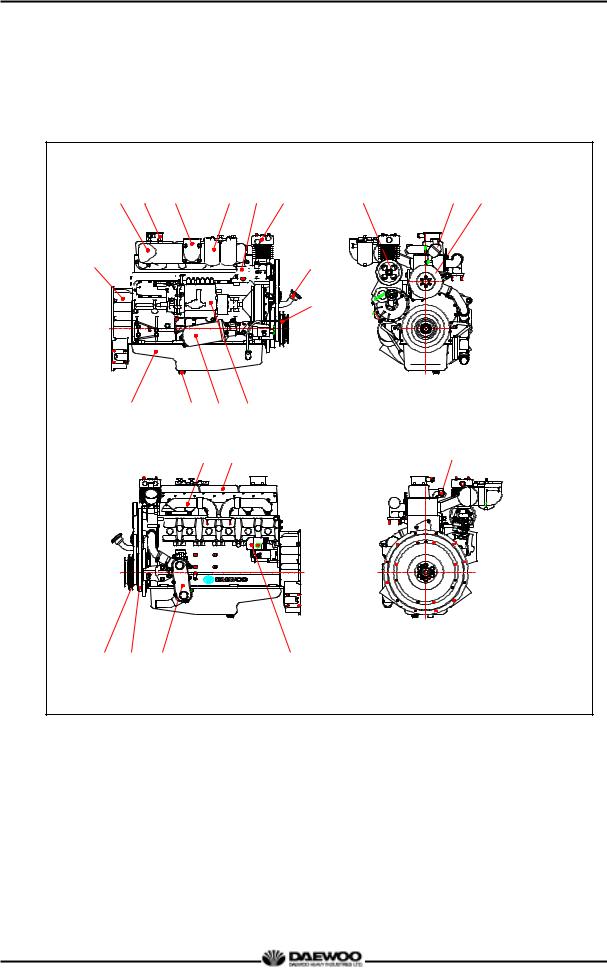
1.4.3.Engine Assembly Views
(1)D1146 (bus)
2 |
3 |
4 |
5 |
6 |
7 |
14 |
15 |
16 |
 8 1
8 1 


9
10 |
11 |
12 |
13 |
17 |
18 |
23 |
19 |
20 |
21 |
22 |
1 |
Flywheel housing |
8 |
Oil filler cap |
16 |
Water pump |
2 |
Intake manifold |
9 |
Oil level gauge |
17 |
Exhaust manifold |
3 |
Breather |
10 |
Oil pan |
18 |
Cylinder head cover |
4 |
Air pipe |
11 |
Oil drain plug |
19 |
Crank shaft pulley |
|
(Air cleaner to intake manifold) |
12 |
Oil filter |
20 |
Vibration damper |
5 |
Fuel filter |
13 |
Fuel injection pump |
21 |
Oil cooler |
6 |
Power steering pump |
14 |
Air compressor pulley |
22 |
Starter |
7 |
Air compressor |
15 |
Thermostat |
23 |
Cooling water pipe |
10
Printed in Jan. 2001 PS-MMA0415-E1A
D1146/D1146TI/DE08TIS
MAINTENANCE MANUAL
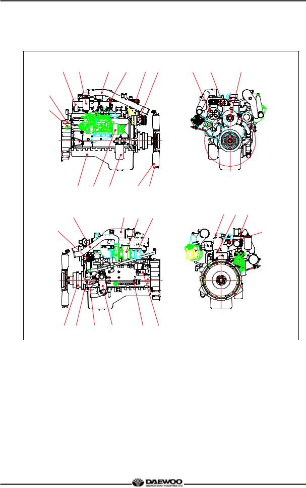
(2) DE08TIS (Truck)
3 |
4 |
5 |
6 |
7 |
8 |
14 |
15 |
16 |
2
1
9 |
10 |
11 |
|
12 |
13 |
|
|
|
18 |
|
|
19 |
20 |
21 |
28 |
29 |
30 |
|
|
|
|
|
||||
17 |
|
|
|
|
|
|
|
31 |
|
22 |
23 |
24 |
25 |
|
26 |
27 |
|
|
|
|
|
|
|
|
|
|||
1 |
Magnetic pick-up sensor |
|
12 |
Cooling fan |
21 |
Exhaust elbow |
|||
2 |
Flywheel housing |
|
13 |
Cooling fan guide |
22 |
Crank shaft pulley |
|||
3 |
Intake manifold |
|
|
14 |
Air compressor pulley |
23 |
Vibration damper |
||
4 |
Fuel filter |
|
|
|
15 |
Thermostat |
24 |
Mounting bracket |
|
5 |
Air pipe |
|
|
|
16 |
Water pump |
25 |
Oil cooler |
|
|
(Intercooler to intake manifold) |
|
17 |
Alternator |
26 |
Starter relay |
|||
6 |
Fuel injection pipe |
|
18 |
Air pipe |
|
27 |
Starter |
||
7 |
Air compressor |
|
|
|
(Turbocharger to intercooler) |
28 |
Breather |
||
8 |
Air con. compressor |
|
19 |
Air pipe |
|
29 |
Water delivery pipe |
||
9 |
Oil pan |
|
|
|
|
(Air cleaner to turbocharger) |
30 |
Air heater relay |
|
10 |
Fuel injection pump |
|
20 |
Turbocharger |
31 |
Cooling water pipe |
|||
11 |
Oil filter |
|
|
|
|
|
|
|
|
|
|
|
|
|
|
11 |
|
|
|
Printed in Jan. 2001 PS-MMA0415-E1A
D1146/D1146TI/DE08TIS
MAINTENANCE MANUAL
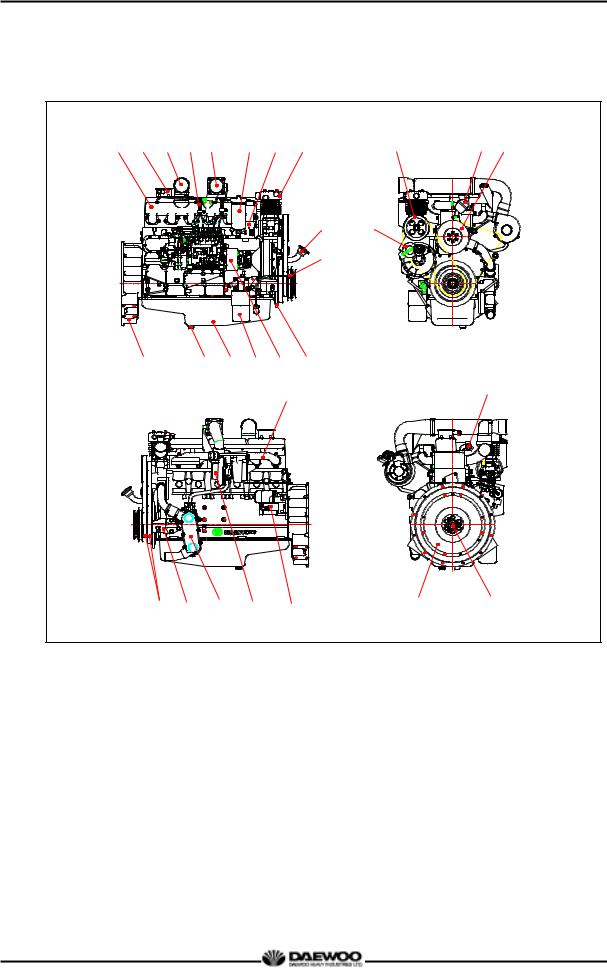
(3) DE08TIS (Bus)
1 |
2 |
3 |
4 |
5 |
6 |
7 |
8 |
18 |
19 |
20 |
9 17
10
11 12 13 14 15 16
21 |
27 |
|
22 |
23 |
24 |
25 |
26 |
28 |
29 |
1 |
Intake manifold |
10 |
Oil level gauge |
20 |
Water pump |
2 |
breather |
11 |
Flywheel housing |
21 |
Exhaust manifold |
3 |
Air pipe |
12 |
Drain plug |
22 |
Belt |
|
(Intercooler to intake manifold) |
13 |
Oil pan |
23 |
Mounting bracket |
4 |
Fuel injection pipe |
14 |
Oil filter |
24 |
Oil cooler |
5 |
Air pipe |
15 |
Fuel injection pump |
25 |
Turbocharger |
|
(Turbocharger to intercooler) |
16 |
Vibration damper |
26 |
Starter |
6 |
Fuel filter |
17 |
Idle gear pulley |
27 |
Cooling water pipe |
7 |
Power steering pump |
18 |
Air compressor pulley |
28 |
Fly wheel |
8 |
Air compressor |
19 |
Thermostat |
29 |
Pilot bearing |
9 |
Oil filler cap |
|
|
|
|
12
Printed in Jan. 2001 PS-MMA0415-E1A

D1146/D1146TI/DE08TIS
MAINTENANCE MANUAL
2. Major Maintenance
2.1. Preventive Maintenance
The preventive maintenance means that the operator performs the servicing of engine to obtain long life and best performance from DAEWOO diesel engine.
2.1.1. Cooling Water
zRegarding the cooling water that is to be used for engine, the soft water not the hard water must be used.
zThe engine cooling water can be used diluting it with antifreezing solution 40% and the additive for rust prevention (DCA4) 3 5 %.
zThe density of above solution and additive must be inspected every 500 hours to maintain it properly.
NOTE :
The proper density control of antifreezing solution and rust preventing additive will be able to prevent the rusting effectively and maintain the stable quality of engine. For the improper control might give the fatal damage to the cooling water pump and cylinder liners, detail care is needed.
zSince D1146, D1146TI and DE08TIS (diesel engine of D1146 series) cylinder liner is dry type, particularly the cooling water control should be applied thoroughly.
zThe density of antifreezing solution and additive for rust prevention is able to be confirmed by the cooling water test kit. (Fleetguard CC2602M or DAEWOO 60.99901-0038)
zHow to use the cooling water test kit
(1)When the cooling water temp. of engine is in the range of 10 55 °C, loosen the plug for cooling water discharge and fill the plastic cup about a half.
NOTE :
In taking the cooling water sample, if the water in auxiliary tank were taken, it is hard to measure the accurate density. Take the cooling water sample necessarily loosening the cooling water discharge plug.
(2)At the state of a test paper soaked in the sampled water, after taking the paper out through water agitation, shake off the water.
13
Printed in Jan. 2001 PS-MMA0415-E1A

D1146/D1146TI/DE08TIS
MAINTENANCE MANUAL
(3) Wait for about 45 sec. till the color change of test paper.
NOTE :
However, it should not elapse longer than 75 sec, and if it did, the hue would change.
(4)Make the numerical value by comparing the test paper which hue has changed with the color list of label on storage bottle.
(5)By comparing the hue changed into yellowish green or so with the green color indication of test paper storage bottle, confirm the density. (Then, the density indication must be in the hue range of 33% to 50%).
(6)The brown at the middle of test paper and the lower pink color indication represent the additive state for rust prevention, and the proper range is that the meeting numerical value of brown (vertical) and pink color (horizontal) locates in the range of 0.3 to 0.8 at the color list of label on the test paper storage bottle.
(7)In case of less than 0.3, replenish the additive for rust prevention (DCA4), and in case of more than 0.8, pour out the cooling water about 50% and then readjust the density after refilling with clean fresh water.
zAmount of Anti-freeze in winter
Ambient |
Cooling water (%) |
Anti-freeze (%) |
|
Temperature (°C) |
|||
|
|
||
Over -10 |
85 |
15 |
|
-10 |
80 |
20 |
|
-15 |
73 |
27 |
|
-20 |
67 |
33 |
|
-25 |
60 |
40 |
|
-30 |
56 |
44 |
|
-40 |
50 |
50 |
2.1.2. Fan belt
zUse a fan belt of specified dimensions, and replace if damaged, frayed, or deteriorated.
zCheck the fan belt for belt tension.
If belt tension is lower than the specified limit, adjust the tension by relocating the alternator. (specified deflection: 10 15 mm when pressed down with thumb)
14
Printed in Jan. 2001 PS-MMA0415-E1A
D1146/D1146TI/DE08TIS
MAINTENANCE MANUAL
2.1.3. Engine oil
zCheck oil level with the oil level gauge and replenish if necessary.
z Check the oil level with the engine cooled. If the engine is warm, allow time for 510 minutes for oil drain into the crankcase before checking oil level. The oil level must be between Max and Min. lines on the gauge.
zEngine oil should be changed at the specified intervals. Oil filter cartridge should be changed simultaneously.
- First oil change : 1,000km(50 hr) operating
First oil change |
After 1,000km (50hr) |
||
|
operation |
||
|
|
||
Short-distance operation vehicle |
D1146/TI |
|
every 10,000km |
(city bus, dump truck) |
DE08TIS |
|
every 20,000km |
Long-distance operation vehicles |
D1146/TI |
|
every 15,000km |
(express bus, cargo truck) |
DE08TIS |
|
every 30,000km |
z The following oils are also recommended
Engine |
Recommend oil |
Remark |
||
|
|
|||
model |
SAE No. |
API No. |
||
|
||||
|
|
|||
|
|
|
|
|
D1146 |
SAE 15W40 |
above CD or CE |
|
|
D1146TI |
|
|||
|
|
|
||
DE08TIS |
SAE15W40 |
ACEA-E2 or ACEA-E3 |
|
|
SAE10W40 |
(API CH-4) |
|
||
|
|
|||
*If long oil change intervals are to be used, ACEA-E3 oil must be used.
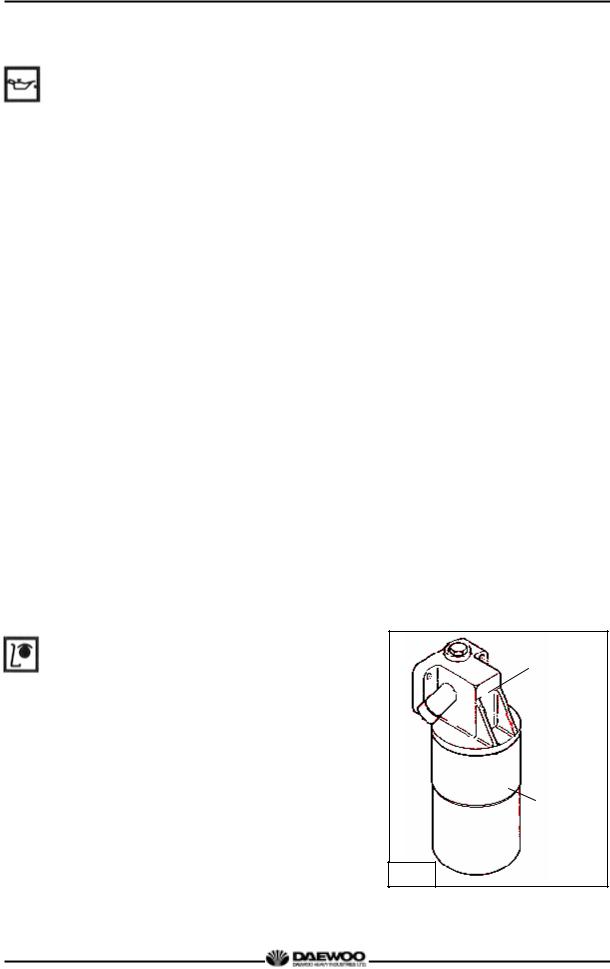
2.1.4.Oil filter
zCheck for oil pressure and oil leaks, and repair or replace the oil filter if necessary.
zChange the oil filter cartridge simultaneously at every replacement of engine oil.
Oil filter head
Oil filter (Cartridge)
G1081
15
Printed in Jan. 2001 PS-MMA0415-E1A
D1146/D1146TI/DE08TIS
MAINTENANCE MANUAL
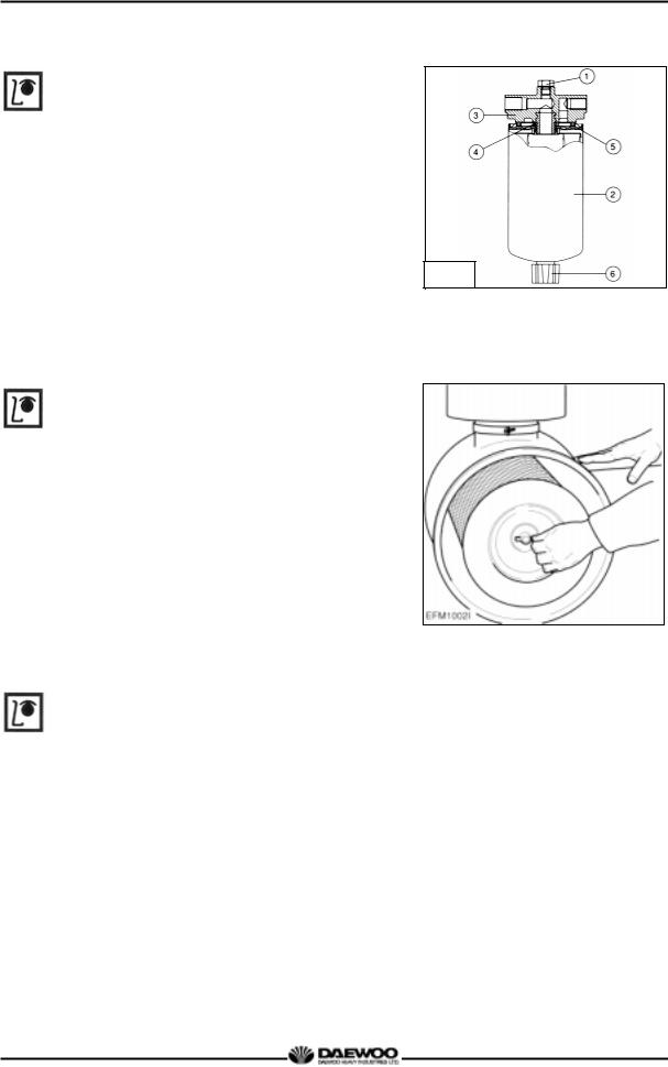
2.1.5. Fuel filter
zDrain water in cartridge with loosening the
cock under filter manually (6) from time to time.
G1019
2.1.6. Air cleaner.
zIn case that elements are deformed, damaged or if the air cleaner has a crack, replace it.
zBy the definite interval, the elements must be cleaned and replaced.
2.1.7. Intercooler
The intercooler is air to air type and has a large
cooling fan capacity. The intercooler life and
performance depends on the intake air condition greatly. Fouled air pollutes and clogs the air fins of intercooler. As a result of this, the engine output is decreased and engine malfunction is occurred. So you always check whether the intake air systems like air filter
element are worn or polluted.
16
Printed in Jan. 2001 PS-MMA0415-E1A
D1146/D1146TI/DE08TIS
MAINTENANCE MANUAL
Air/air intercooler with radiator (combined radiator)
 Air flow by cooling fan
Hot air by turbo charger compressor
Cooled air to intake manifold (max. 50°C)
2.1.8. Valve clearance adjust procedure
|
zAfter |
letting the #1 cylinder's piston |
|||
|
come at |
|
|
|
|
the compression top dead center by turning |
|||||
|
the crankshaft, adjust the valve clearances. |
||||
|
zLoosen the lock nuts of rocker arm |
||||
|
adjusting screws and push the feeler gauge |
||||
|
of specified value between a rocker arm and |
||||
|
a valve stem and adjust the clearance with |
||||
|
adjusting screw respectively and then tighten |
||||
|
with the lock nut. |
|
|
|
|
z As for the valve clearance, adjust it when in |
|||||
|
cold, as follows. |
|
|
|
|
|
|
|
|
|
|
|
Model |
Intake Valve |
|
Exhaust Valve |
|
|
D1146 |
|
|
|
|
|
D1146TI |
0.3 mm |
|
0.3 mm |
|
|
DE08TIS |
|
|
|
|
1) Rotate the crankshaft to overlap the intake |
|||||
|
and the exhaust valves of #6, then #1 cylinder |
||||
|
become the compression state of top dead |
||||
|
center. |
|
|
|
|
2) Therefore |
adjust the |
|
valve clearance |
||
|
corresponding to “ |
” of lower figure. |
|||
At this time there are no force on the push rods of #1 cylinder.
17
Printed in Jan. 2001 PS-MMA0415-E1A

D1146/D1146TI/DE08TIS
MAINTENANCE MANUAL
3)Rotating the crankshaft by one revolution, #6 cylinder become the compression state of top dead center.
4)Thereafter adjust the valve clearances corresponding to “  ” of lower figure.
5)After reinsuring the valve clearances, retighten if necessary.
z No. 1 cylinder is located at the side where flywheel was installed.
Flywheel |
Intake Valve |
Exhaust Valve Cylinder No. |
Cooling Fan |
G1048
2.1.9. Cylinder compression pressure
zStop the engine after warming up, and
take out nozzle holder assembly.
G1067
18
Printed in Jan. 2001 PS-MMA0415-E1A
D1146/D1146TI/DE08TIS
MAINTENANCE MANUAL
z Install the special tool (compression gauge adapter) at the nozzle holder hole, and connect the compression pressure gauge there.
|
Standard value |
28kg/cm2 over |
|
|
|
|
Limit value |
24kg/cm2 |
|
|
|
|
Difference |
Within ± 10 % |
|
|
|
|
between each cylinder |
|
|
|
|
|
|
|
|
|
|
♦ Condition : Water temperature 20°C, |
|
|
|
||
|
G1068 |
|
|||
|
Engine rotation 200rpm (10 rotations) |
|
|
||
|
|
|
|
||
|
|
|
|
||
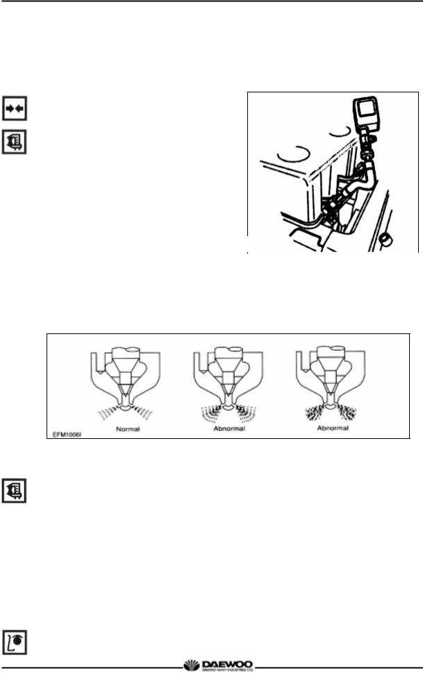
2.1.10. Injection nozzle
z Install a nozzle on the nozzle tester.
zIf the inspected injection pressure is less than the specified value, adjust using the adjusting shims.
Engine Model |
D1146 |
|
D1146TI |
|
DE08TIS |
|
|
|
|
|
|
Opening pressure |
210 kg/cm |
2 |
214 kg/cm |
2 |
1st : 160 kg/cm2 |
|
|
2nd : 220 kg/cm2 |
zCheck the atomizing state and replace it if abnormal.
2.1.11.Fuel injection pump
zCheck the housing crack, damage etc. and replace it if abnormal.
19
Printed in Jan. 2001 PS-MMA0415-E1A
D1146/D1146TI/DE08TIS
MAINTENANCE MANUAL
zCheck if the idle operation and speed regulating lever's sealing is removed.
z The adjustment and testing of fuel injection pump should necessarily be done at the test bench.
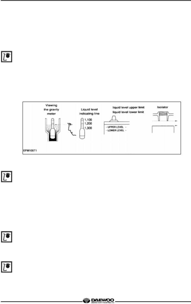
2.1.12. Battery
zInspect for any leakage of electrolytic solution owing to battery crack, and replace
the battery in case of poor condition.
zInspect for amount of electrolytic solution, and replenish if insufficient.
zMeasure the gravity of electrolytic solution, if less than specified value (1.12 1.28), replenish.
2.1.13. Air removal of fuel system
The suction room of fuel injection pump has the function of air removal continuously during the operation through a relief valve.
In case that the suction room lacks fuel at all, for instance, in case of new installation of injection pump, after loosening the air removing screws of cartridge filter respectively, remove the air by operating the manual pump of fuel supply pump until bubble will disappear.
2.1.14. Fuel supply pump
Every time of engine oil replacement, the fuel strainer installed at the fuel supply pump should be removed and cleaned.
2.1.15. Turbocharger
The turbocharger needs not arty special equipment.
Every time of engine replacement, a leakage or clogging of oil pipes should be inspected. Air cleaner should be maintained carefully for nut or foreign material not to get in. Periodic inspection should be applied on the compressed air and exhaust gas
20
Printed in Jan. 2001 PS-MMA0415-E1A

D1146/D1146TI/DE08TIS
MAINTENANCE MANUAL
pipes, For leaking air will bring the overheat engine, an immediate repair must be done.
During the operation that is surrounded by the dust and oil mixed air, frequent cleaning must be done on the impellers. Tear down the impeller casing (attention: be careful not to bend) and must clean with non-acid solvent solution. If necessary, use plastic scraper If impeller is severely polluted, dip the impeller into solution and may be better to clean it with stiff brush.
Then one thing to beware is to dip only impeller part and so do not support by impeller but bearing housing.
2.1.16. Starting motor
In case of engine maintenance, clean pinion and ring gear thoroughly putting in the fuel, and coat them with grease.
Also, In case of washing engine (room) and so forth, inspect the wiring state being careful for water not to get in.
21
Printed in Jan. 2001 PS-MMA0415-E1A
D1146/D1146TI/DE08TIS
MAINTENANCE MANUAL
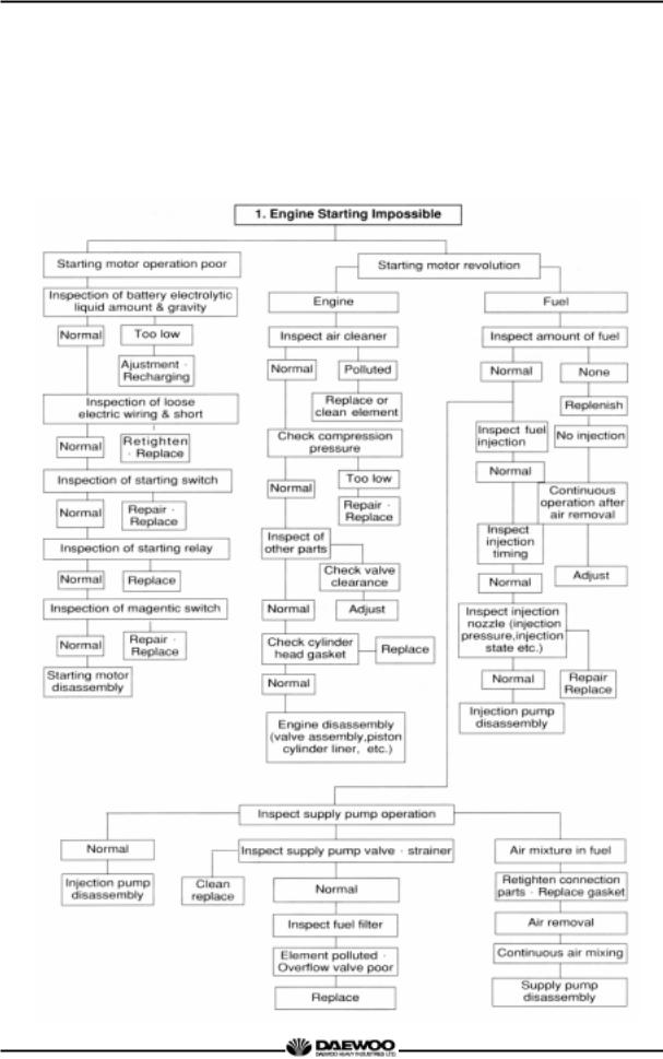
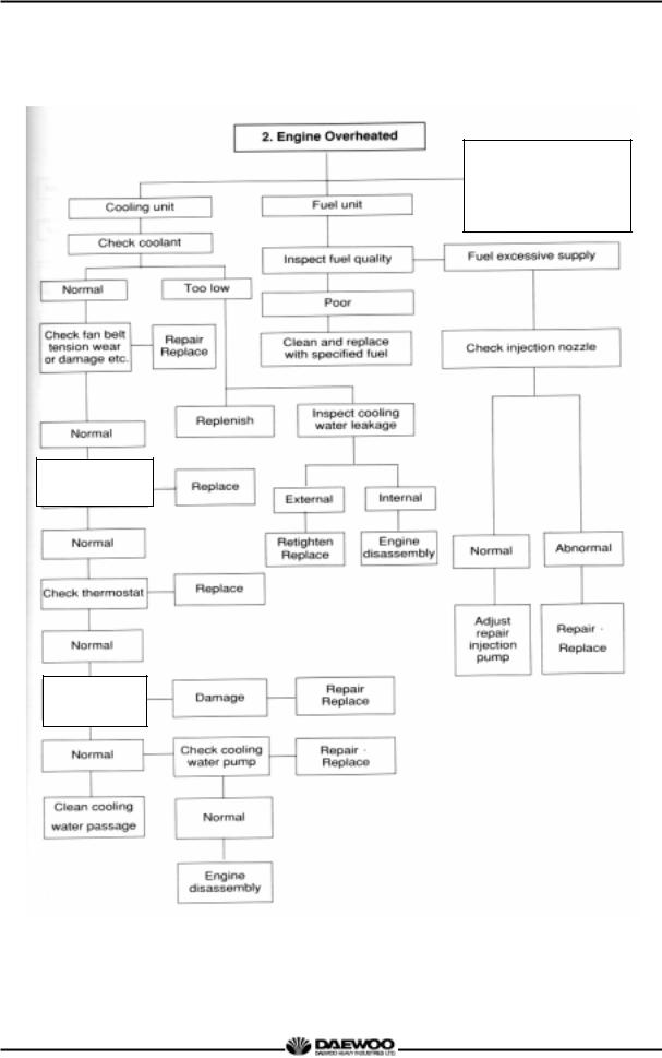
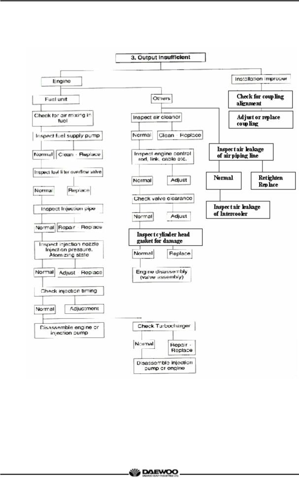
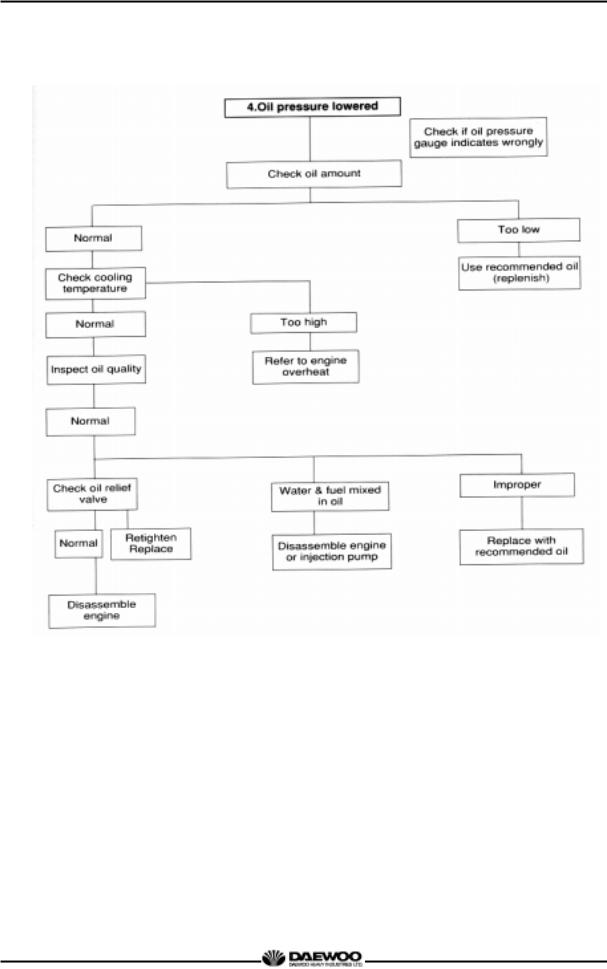
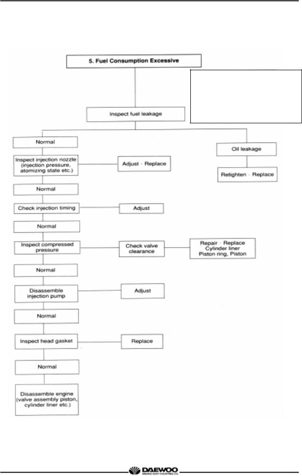
2.2. Diagnosis and Remedy
zThe following description summarizes the probable cause of and remedy for generall failure by item.
zImmediate countermeasures should be taken before a failure is inflamed if any symptom is detected.
22
Printed in Jan. 2001 PS-MMA0415-E1A
D1146/D1146TI/DE08TIS MAINTENANCE MANUAL
Check fresh Radiator tank cap
Operating state
1.Overload
2.Radiator core clogged
3.Continuous over-run
Inspect
Radiator
23
Printed in Jan. 2001 PS-MMA0415-E1A
D1146/D1146TI/DE08TIS
MAINTENANCE MANUAL
24
Printed in Jan. 2001 PS-MMA0415-E1A
D1146/D1146TI/DE08TIS
MAINTENANCE MANUAL
25
Printed in Jan. 2001 PS-MMA0415-E1A
D1146/D1146TI/DE08TIS
MAINTENANCE MANUAL
Causes according to operating conditions
1.Overload
2.Freqent use of low geae position at high speed
3.Freqent use of high geae position at low speed
4.Clutch slip
5.Too low tire inflation pressure
26
Printed in Jan. 2001 PS-MMA0415-E1A
 Loading...