


Bosch HDS255U, HDS7022C, HDS252U, HDS252C, HDS7022U Manual
...Installation Instructions
Freestanding Dual Fuel Range
For Use With |
|
|
|
|
|
|
|
|
|
|
||||||||||||||||||||||||||||||||||||||||||
Bosch Dual Fuel Ranges |
|
|
|
|
|
|
|
|
|
|
||||||||||||||||||||||||||||||||||||||||||
|
|
|
|
|
|
|
|
|
|
|
|
|
|
|
|
|
|
|
|
|
|
|
|
|
|
|
|
|
|
|
|
|
|
|
|
|
|
|
|
|
|
|
|
|
|
|
|
|
|
|
|
|
|
|
|
|
|
|
|
|
|
|
|
|
|
|
|
|
|
|
|
|
|
|
|
|
|
|
|
|
|
|
|
|
|
|
|
|
|
|
|
|
|
|
|
|
|
|
|
|
|
|
|
|
|
|
Quick Finder: |
|
|
|
|
|
|
|
|
|
||||||||||||||||||||||||||||||||||||||||||
|
|
|
|
|
|
|
|
|
|
|
|
|
|
|
|
|
|
|
|
|
|
|
|
|
|
|
|
|
|
|
|
|
|
|
|
|
|
|
|
|
|
|
|
|
|
|
|
|
|
|
1 |
|
|
Safety |
|
|
|
|
|
|
|
|
|
|
|
|
|
|
|
|
|
|
|
|
|
|
|
|
|
|
|
|
|
|
|
|
|
|
|
|
|
|
|
|
|
|
|
|
|
|
|
|
|
||
|
|
|
|
|
|
|
|
|
|
|
|
|
|
|
|
|
|
|
|
|
|
|
|
|
|
|
|
|
|
|
|
|
|
|
|
|
||||||||||||||||
|
Preparation |
|
|
|
|
|
|
|
|
|
|
|
|
|
|
|
|
|
|
|
|
|
|
|
|
|
|
|
|
|
|
3 |
||||||||||||||||||||
|
|
|
|
|
|
|
|
|
|
|
|
|
|
|
|
|
|
|||||||||||||||||||||||||||||||||||
|
Installation |
|
|
|
|
|
|
|
|
|
|
|
|
|
|
|
|
|
|
|
|
|
|
5 |
||||||||||||||||||||||||||||
|
|
|
|
|
|
|
|
|
|
|
|
|
||||||||||||||||||||||||||||||||||||||||
|
Final Steps |
|
|
|
|
|
|
|
|
|
|
|
|
7 |
||||||||||||||||||||||||||||||||||||||
|
|
|
|
|
|
|
|
|||||||||||||||||||||||||||||||||||||||||||||

 Important Safety Instructions
... Our Inspiration
Table of Contents |
|
Important Safety Instructions .......................................................................................... |
1 |
Preparation ................................................................................................................... |
3 |
Installation .................................................................................................................... |
5 |
Final Steps ................................................................................................................... |
7 |
Please read all instructions before using this appliance. |
|
PARTSPROVIDED:
Anti-Tip Bracket
TOOLSANDPARTSNEEDED:
•Range Power Supply Cord Kit with strain relief (240V - 30 Amps)*
•Standard Measuring Tape
•Phillips Head Screwdriver
•1-1/4” Wrench
•Pencil
•T-20 Torx Screwdriver
•3/8” Nut Driver
•Screws (2) and Anchors (2) for Anti-tip Bracket (Style will vary depending on mounting surface)
•Pipe Wrench (2)
•Teflon® Tape** or Pipe Joint Compound (Appropriate for use with LP gas and Natural gas)
•Channel Lock Pliers
•Gas Leak Test Solution
•Level
•Drill and Drill Bit
•Gas Supply Line (Flexible Metal Appliance Connector or Rigid Pipe)
•Gas Shut Off Valve (If not already present)
•Gloves and Safety Goggles
*Not needed for Canadian installations
**Teflon is a registered trademark of DuPont
WARNING
If the information in this manual is not followed exactly, a fire or explosion may result causing property damage, personal injury or death.
•Do not store or use combustible materials, gasoline or other flammable vapors and liquids in the vicinity of this or any other appliance.
•WHATTODOIFYOUSMELLGAS:
•Do not try to light any appliance.
•Do not touch any electrical switch.
•Do not use any phone in your building.
•Immediately call your gas supplier from a neighbor’s phone. Follow the gas supplier’s instructions.
•If you cannot reach your gas supplier, call the fire department.
Installation and service must be performed by a qualified installer, authorized service agency or the gas supplier.
•Remove all tape and packaging before using the range. Destroy the carton and plastic bags after unpacking the range. Never allow children to play with packaging material.
•Be sure your appliance is properly installed and grounded by a qualified technician in accordance with the National Electrical Code ANSI/ NFPA No. 7 latest edition and local electrical code requirements.
Important: Local codes vary. Installation, electrical connections and grounding must comply with all applicable codes.
•Install only per installation instructions included in the literature package for this range.
•Ask your dealer to recommend a qualified technician and an authorized repair service.
•Know how to disconnect the power to the range at the circuit breaker or fuse box in and the gas supply at the shutoff in case of an emergency.
•Do not repair or replace any part of the applianceunlessspecificallyrecommendedin the manuals. All other servicing should be done by a qualified technician. This may reduce the risk of personal injury and damage to the range.
•When testing the supply piping system at test pressures in excess of 1/2 psig (3.5 kPa), the appliance and its individual shutoff valve must be disconnected from the gas piping system.
•When testing the supply piping system at test pressures equal to or less than 1/2 psig (3.5 kPa), the appliance must be isolated from the gas supply piping system by closing its individualmanualshutoffvalve.
•Never modify or alter the construction of a range by removing leveling legs, panels, wire covers, anti-tip brackets/screws, or any other part of the product.
•Do not lift door by door handle. Remove the door for easier handling and installation. See Section ‘Removing Oven Door’ in Use and Care manual.
Instructions Safety
Installation Preparation
Steps Final
English • 1
Your Life ... |
IMPORTANT SAFETY INSTRUCTIONS |
|
Safety Instructions
Installation Preparation
Final Steps
WARNING
Before installing, turn power OFF at the service panel. Lock service panel to prevent power from being turned ON accidentally.
CAUTION
Unit is heavy and requires at least two persons or proper equipment to move.
WARNING
Stepping, leaning or sitting on the doors or drawers of this range can result in serious injuries and also cause damage to the range. Do not allow children to climb or play around the range. The weight of a child on an open door may cause the range to tip, resulting in serious burns or other injury.
CAUTION
Do not use the oven or warming drawer (if equipped) for storage.
 WARNING
Do not store items of interest to children in the cabinets above the range or on the backguard of a range. Children climbing on the range to reach items could be seriously injured.
This appliance has been tested in accordance with the following standards:
•ANSI Z21.1, Standard for Household Cooking Appliances (USA)
•CAN 1.1-M81 Interim Reqt # 58 Domestic Cooktops (CANADA)
•CAN/ CSA-C 22.2 No. 61-M89 Household Cooking Ranges
In Canada, installation must be in accordance with CAN 1-B149.1 and .2 Installation Codes for Gas Burning Appliances and/or local codes.
For Massachusetts Installations:
1.Installation must be performed by a qualified or licensed contractor, plumber or gas fitter qualified or licensed by the state, province or region where this appliance is being installed.
2.Shutoff valve must be a “T” handle gas cock. 3.Flexible gas connector must not be longer than 36
inches.
HighAltitude InstallationNote:
This range is CSA certified for safe operation up to an altitude of 10,000 ft. without any modifications.
Exception: for use with LP, the range must first be converted using the LP conversion instructions included in this literature package.
 WARNING
RANGE TIPPING HAZARD
•All ranges can tip and injury could result. To prevent accidental tipping of the range, attach it to the wall, floor or cabinet by installing the Anti-Tip Device supplied.
•A risk of tip-over may exist if the appliance is not installed in accordance with these instructions.
•If the range is pulled away from the wall for cleaning, service, or any other reason, ensure that the Anti-Tip Device is properly reengaged when the range is pushed back against the wall. In the event of abnormal usage (such as a person standing, sitting, or leaning on an open door), failure to take this precaution could result in tipping of the range. Personal injury might result from spilled hot liquids or from the range itself.
English • 2

Steps 1 through 4: Preparation
... Our Inspiration
1. Install Ventilation
Bosch strongly recommends the installation of a ventilation hood above this range. For most kitchens a certified hood rating of not less than 300 CFM is recommended. The range hood must be installed according to instructions furnished with the hood.
2. Prepare Cabinets
This unit is designed for installation near adjacent walls and projecting surfaces constructed of combustible materials.
Allow a minimum of 30 inches between cabinets where range is to be installed (See Figure 1)**.
RequiredClearances*
From cooktop to materials above (See Figure 1) There must be a minimum clearance of 30 inches between the top of the cooking surface and the bottom of an unprotected wood or metal cabinet.
24 inches is acceptable when the bottom of the wood or metal cabinet is protected by (a) not less than 1/4" of flame retardant material which must be covered with
(b) not less than No. 28 MSG sheet metal, 0.015 inch stainless steel’ or 0.024 inch aluminum or copper.
From range walls to adjacent materials(SeeFigure1) No clearance is required from unit walls to adjacent vertical combustible walls on rear, right or left.
Clearance from range top to adjacent vertical walls must be at least 4”.
NOTE: Some cabinet finishes cannot survive the temperatures allowed by U.L., particularly self-cleaning ovens; the cabinets may discolor or stain. This is most noticeable with laminated cabinets.
3. Prepare Gas Supply Line and Electrical Outlet
The gas supply line and electrical outlet must be located in the shaded space in Figure 2.
4. Prepare Walls and Floor
Seal any holes in the walls or floor. Remove any obstructions (extra electrical or gas connections, etc.) so that range will rest against wall properly.
Install Anti-Tip Bracket
1.Adjust height of range and level by rotating the adjustable leg supports on the bottom of the range, using 1-1/4" wrench.
2.Measure to locate bracket position as shown in Figure 8.
3.Secure bracket with 2 screws adequate for mounting surface, not included. (i.e.; for wood floor use wood screws, for concrete floor use concrete anchors and screws.).
|
|
|
Safety |
30” Minimum |
|
|
Instructions |
Centered |
30” |
|
|
|
Min. |
18” |
|
|
|
||
4” Min. |
|
4” Min.Min. |
|
No Clearance to |
|
||
|
|
||
Cabinet Wall |
|
|
|
Required ** |
|
|
|
Figure 1: Cabinet Preparation
|
Place Gas Supply |
Preparation |
||
|
Line and Electrical |
|
||
|
Outlet Here |
|
||
771/2"1/2” |
|
|
|
|
|
|
331/2"1/2” |
|
|
4 " |
13131/8”" |
4”" 37/8”/8" 4 1/2” |
|
|
4 1/2” |
|
2" |
|
|
|
|
|
||
|
30”" |
|
Installation |
|
|
|
9/16”1 |
||
Figure 2: Gas Supply Line and Electrical Outlet Placement |
|
|||
|
|
Backwall |
|
|
|
|
Flush |
|
|
Cabinet Sidewall |
|
|
||
|
|
Anti-Tip Device |
|
|
Figure 3 |
|
|
Final |
|
|
Tips: |
|||
|
|
|||
Tape warming drawer shut to keep it from opening |
Steps |
|||
while installing the range. |
||||
|
||||
During installation, place a portion of the box or a piece of cloth under the range to protect floors.
To make range lighter and easier to handle, remove door (see instructions in Use and Care manual).
*Instructions were determined using standard American cabinets. Standard base cabinets measure 36" high x 24" deep . Cabinets over the cooking surface and cabinets adjacent to those over the cooking surface measure 13 inches deep from backwall. If nonstandard cabinets are used, care should be taken to alter dimensions accordingly.
** 12 mm clearance from range sidewall to cabinet required in Canada.
Your Life ...
Step 5: Prepare Electrical Connection
Safety Instructions
Preparation
Installation
Final Steps
English
5. Prepare Electrical Connection
Ranges are dual rated for use on either 120/240 VAC or 120/208 VAC. See chart below for power ratings and circuit breaker sizes based on the supply voltage for each model.
MODEL: HDS |
|
|
|
|
VOLTS |
|
HZ |
RATING |
CIRCUIT |
A.C. |
|
|
KW |
BREAKER |
120/240 |
|
60 |
6.5 |
30 AMPS |
120/208 |
|
60 |
4.8 |
30 AMPS |
CAUTION:
Make certain that gas shutoff valve and all burner controls are in the OFF position before beginning
Verify that wiring to house is adequate.
Contact your local utility company to verify that the present electric service to your home is adequate. In some instances, the size of the wiring to the house and service switch must be increased to handle the electrical load demanded by the range.
Verify that wiring inside house is adequate.
Most wiring codes require a separate circuit with separate disconnect switch and fuses either in the main entrance panel or in a separate switch and fuse box.
The range requires a three wire 120/240 or 120/208 volt, 30 AMP, 60 Hz AC circuit.
Most local building regulations and codes require that electrical wiring be done by licensed electricians. Be sure to install your range according to the electric codes in place in your region.
 To prevent electrical shock, the grounding prong on the range cord should not be cut or removed under any circumstances. It must be plugged into a matching grounding type receptacle and connected to a correctly polarized 240Volt circuit. If there is any doubt as to whether the wall receptacle is properly grounded, have it checked by a qualified
electrician.
GeneralInformation
Bosch recommends that the range be installed with a power cord set (not supplied)*. The electrical rating of the power cord set must be 120/240 volt, 30 amperes minimum. The power cord set shall be marked “For Use with Ranges.” Always use a new power cord.
Note: In Canada, the range is shipped from the factory with the range cord already installed. Proceed to “Step 7: Installation - Connect the Gas Supply)
For installations other than those in Canada, connect the range cord at the terminal block (See next page for detailed instructions). Access the terminal block by removing the cover in the lower right hand corner of the range back panel (See Figure 4). Install the strain relief (see next column) and the proper connector through the knockout(s) provided. The electrical supply, including flexible conduit or power cord, should be restricted to the shaded areas in Figure 2 (previous page)
*Not needed for Canadian installations
•4
InstallStrainRelief
Place strain relief in knockout below terminal block (See Figure 4). Feed range cord through hole and strain relief up to terminal block. Allow for slack in the cord between the strain relief and terminal block. Once cord length/ slack has been adjusted, attach strain relief per instructions included with strain relief.
 WARNING
The strain relief provided with your range cord must be properly installed.
TIP
The knockout panel below the terminal block can be removed from the range to install the strain relief: Remove knockout panel from range, install strain relief in panel and reattach. DO NOT remove entire range back panel.
Electric Connection (found |
|
behind terminal block |
|
cover) |
Feed |
|
|
|
Range |
|
Cord |
|
Through |
|
Strain |
|
Relief in |
|
Knockout |
|
Panel |
|
Here |
Gas Connection |
|
Figure 4
 WARNING
Risk of Electric Shock or Fire. Frame grounded to neutral through a ground strap. Grounding through the neutral conductor is prohibited for new branch-circuit installations (1996 NEC), mobile homes, and recreational vehicles, or in an area where local codes prohibit grounding through the neutral conductor.
For installations where grounding through the neutral conductor is prohibited, (a) disconnect the link from the neutral,
(b) use grounding terminal or lead to ground unit, (c) connect neutral terminal to lead branch circuit neutral in usual manner (when the appliance is to be connected by means of a cord kit, use 4-conductor cord for this purpose).
Use only cord kits rated 125/250 volts (minimum), 30 amperes and labeled “For Use with Ranges”. Strain relief provided with cord must be installed per instructions included with cord.
Figure 5

Step 6: Installation - Connect Electric
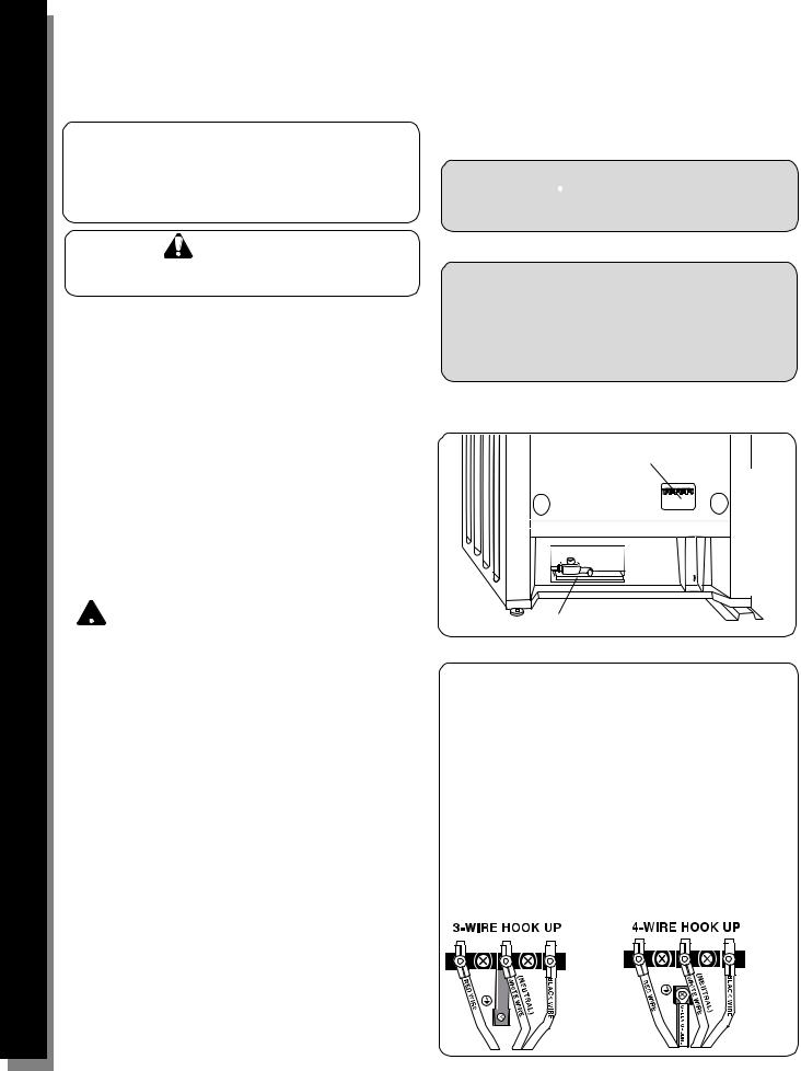
Three Wire Connection
The Four Wire Connection is preferred, but where local codes and ordinances permit grounding through neutral and/or conversion to four wire is impractical, unit may be connected to the power supply via a three wire connection.
1.Disconnect electrical power at breaker box.
2.Remove the terminal block cover to expose the terminal block (See Figure A).
3.Remove top nut, star washer, and round washer from each post.
Note: DO NOT remove last round washer, last nut or internal wiring leads.
4.Attach white wire, round washer, star washer and nut IN THIS ORDER on top of ground strap on center post.
5.Attach red wire, round washer, star washer and nut IN THIS ORDER to left post.
6.Attach black wire, round washer, star washer and nut IN THIS ORDER to right post (See Figure B).
7.Tighten all connections securely and replace terminal block cover (See Figure C).
8.Properly secure strain relief (see previous page).
Figure 6
White
Red
Ground Strap
Figure 7
... Our Inspiration
Instructions Safety
Black
Preparation
FourWireConnection(Preferred to three wire connection).
1.Disconnect electrical power at breaker box.
2.Remove the terminal block cover to expose the terminal block (See Figure A).
3.Remove top nut, star washer, and round washer from each post.
Note: DO NOT remove last round washer, last nut or internal wiring leads.
4.Remove screw from bottom end of ground strap.
5.Remove ground strap from center post, rotate so that wide end is at top and attach wide end to range through hole below junction box. Attach green wire on top of ground strap. Tighten Screw (See Figure D).
6.Attach red wire, round washer, star washer and nut IN THIS ORDER to left post.
7.Attach white wire, round washer, star washer and nut IN THIS ORDER to center post.
8.Attach black wire, round washer, star washer and nut IN THIS ORDER to right post (See Figure E).
9.Tighten all connections securely and replace terminal block cover.
10.Properly secure strain relief (see previous page).
Note: DO NOT plug in range at this time. Proceed to step 7, next page.
Black
Ground  White
White
Strap
Red Green Ground Screw
Figure 8
Green Ground Screw
Ground |
Green |
|
Strap |
||
|
Figure 9
Black
White
Red
Figure 10
Installation
Steps Final
English • 5
Your Life ...
Step 7: Installation - Connect Gas Supply
Preparation Safety Instructions
Installation
Final Steps
Important note for LP users: The range is shipped from the factory for use with natural gas. For use with propane (LP) gas, your range must first be converted using the LP conversion kit.
The gas connection is located below the back panel of the range (See Figure 4, Page 4). It is accessible through the warming drawer access panel or from the back of the range. To reach access panel, remove warming drawer.
Shut off main gas supply valve before disconnecting the old range and leave it off until the new hook-up has been completed. Don’t forget to relight the pilot on other gas appliances when you turn the gas back on.
The range can be installed using rigid pipe or a CSA International-certified flexible metal appliance connector. If using a flexible connector, always use a new connector.
Apply pipe joint compound or Teflon** tape appropriate for use with LP gas and Natural gas around all male pipe threads to prevent leaks.
If not already present, install gas shut off valve in an easily accessible location. Make sure all users know where and how to shut off the gas supply to the range.
Note: The installer should inform the consumer of the location of the gas shutoff valve.
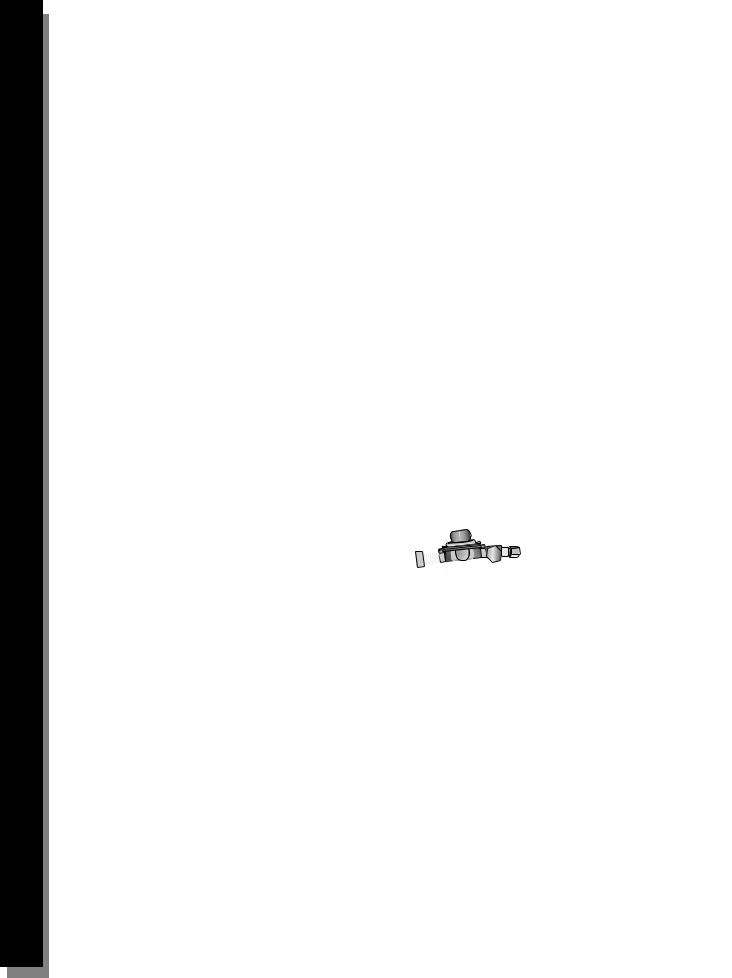
Flexible Connector Method (see Figure 11, this page)
1.Install male 1/2” flare adaptor at the 1/2” NPT internal thread of the range inlet. Use a backup wrench on the elbow fitting to avoid damage.
2.Install male 1/2” or 3/4” flare union adapter on the NPT internal thread of the manual shutoff valve.
3.Connect flexible metal appliance connector.
4.Make sure circuit breaker is off and then plug range cord into electrical outlet.
5.Push range back into position insuring that range leg
slides under the anti-tip bracket. The range will sit 3/4” away from the wall when properly installed.
Note: Be careful not to crimp flexible connector!
6.Carefully tip range forward to ensure that anti-tip bracket engages and prevents tip-over.
Rigid Pipe Method (see Figure 12, this page)
The configuration of the rigid pipe connection will vary depending on the location of the gas pipe stub. Refer to Figure 12 for details.
1.Make sure circuit breaker is off and then plug range cord into electrical outlet.
2.Push range back into position ensuring that range leg slides under the anti-tip bracket. The range will sit 3/4” away from the wall when properly installed.
3.Carefully tip range forward to ensure that anti-tip bracket engages and prevents tip-over.
4.Connect pipe to range at union. Access the connection through the access panel behind the warming drawer.
Note: Be careful not to apply pressure to warming drawer element during rigid pipe installation.
Proceed to “Test for Gas Leaks”, next column.
Test for Gas Leaks
Leak testing is to be conducted by the installer according to the instructions given in this section.
Turn on Gas. Apply a non-corrosive leak detection fluid to all joints and fittings in the gas connection between the shutoff valve and the range. Include gas fittings and joints in the range if connections may have been disturbed during installation. Bubbles appearing around fittings and connections indicate a leak.
If a leak appears, turn off supply line gas shutoff valve and tighten connections. Retest for leaks by turning on the supply line gas shutoff valve. When leak check is complete (no bubbles appear), test is complete. Wipe off all detection fluid residue. Proceed to Steps 8A and 8B: Final Steps.
CAUTION
NEVER CHECK FOR LEAKS WITH A FLAME.
DO NOT CONTINUE TO THE NEXT STEP UNTIL ALL LEAKS ARE ELIMINATED.
CAUTION
Before you plug in an electrical cord, be sure all controls are in the OFF position.
Gas Shut-
Off Valve
Regulator |
Flexible |
|
Connector |
Figure 11: Flexible Connector Method
elbow |
gas shut off valve |
elbow |
nipple |
|
union |
nipple |
|
|
nipple |
|
elbow: |
|
connect to |
1/2” to 3/4” |
regulator here |
gas pipe |
Gas Flow to Range
Figure 12: Rigid Pipe Method
** Teflon is a registered trademark of DuPont
English • 6
Step 8: Test the Installation
... Our Inspiration
8A. Test Electric Ignition
Turn on power at breaker.
 Caution:
If the display flashes and beeps, the polarity of the wiring may be reversed. Reversed polarity can damage the range and can result in electrical shock hazard. Immediately switch off power at the breaker and return to step 6.
Select a rangetop burner knob. Push down and turn to the flame symbol. If the ignitor/spark module is operating correctly, it will produce a clicking sound. Once the air has been purged from the supply lines, the burner should light within four (4) seconds. After burner lights, turn knob to the off position.
Test each rangetop burner in this fashion.
Call Bosch Service at 800-944-2904 if any of the burners do not light.
Some yellow streaking is normal during the initial start-up.
Allow unit to operate 4-5 minutes and reevaluate before making adjustments.
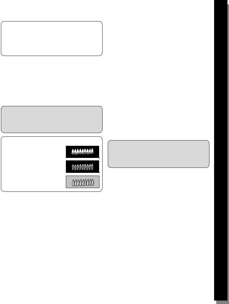
Flame Characteristics
YellowFlames:
Further adjustment is required.
Yellow Tips on Outer Cones:
Normal for LP Gas.
SoftBlueFlames:
Normal for Natural Gas.
8B. Test/Adjust Flame
HighSetting:
The combustion quality of the flame for each burner must be visually inspected. For propane, the flame should be blue with yellow tips. For natural gas, it should be soft blue in color. The flame should carry over, or surround, the entire burner and should not lift or blow off the burner.
To inspect, turn the burner on. See Figure 13 for appropriate flame characteristics.
If the flame is completely or mostly yellow, verify that the regulator is set for the correct fuel. After adjustment, retest. If any of the burners continue to burn mostly or completely yellow, call Bosch Service800-944-2904.
Note: With LP use, some yellow tipping on outer cones is normal.
Low Setting
All burners must also be inspected for carry-over. On low, the flame should completely surround the burner. If any of the cooktop burners do not carry over on the low setting, call Bosch Service 800-944-2904.
Installation is complete at this time.
WHENPROPERLYADJUSTED:
There should be a flame at each burner port.
There should be no air gap between the flame and burner.
Figure 13
Replacement Parts: Visit your Bosch dealer for replacement parts. For a dealer near you contact Bosch Service at 800-944-2904.
Preparation Instructions Safety
Installation
Steps Final
English • 7
 Loading...