


HGS256UC-01
Bosch HGS256UC-01, HGS252UC-01, HGS445UC-01, HGS446UC-01, HGS442UC-01 Installation Instructions Manual
...
ATTENTION PROPANE USERS: DO NOT ATTEMPT TO CONNECT THiS RANGE
TO PROPANE USING THE NATURAL GAS CONNECTION DESCRIBED IN THIS
MANUAL
PUease see the "LP Conversion Instructions" incUuded in this Uiterature kit to convert this range
for propane use,

Praise read all instructions before using this applianceo
Table of Contents
Safety Instructions and Applicable Codes ........................................................................... i,2
Install Ventilation, Prepare Cabinets and Install Anti=Tip Bracket ............................................... 3
Connect Gas ....................................................................................................................... 4
Test Burner Function ............................................................................................................ 5
Adjust the Flame ................................................................................................................. 6
, Remove all tape and packaging before using the range.
Destroy the carton and plastic bags after unpacking the
range. Never allow children to play with packaging material.
Install only per these installation instructions.
Ask your dealer to recommend a qualified technician and an
authorized repair service. Know how to disconnect the power to
the range atthe circuit breaker or fuse box and the gas supply at
the shutoff in case of an emergency.
Note: This range is not designed for manufactured (mobile)
home installation.
User servicing - Do not repair or replace any part of the
appliance unless specifically recommended in the manuals. All
other servicing should be done by a qualified technician. This
may reduce the risk of personal injury and damage to the range.
PARTS PROVIDED
Anti-Tip Bracket
TOOLS AN DPARTS NEEDED:
* Standard Measuring Tape
* Phillips Head Screwdriver
* !=!/4"Wrench
* Pencil
o =1==20Torx Screwdriver
* 3/8" Nut Driver
o Screws (2) and Anchors (2) for Anti-tip Bracket (Style will
varydepending on mounting surface)
, PipeWrench (2)
* Teflon® Tape* or Pipe Joint Compound (Appropriate for use
with LP gas and Natural gas)
o Channel Lock Pliers
* Gas Leak Test Solution
* Level
* DriUand Ddl[ Bit
* GasSupply Line (Flexible HetalAppliance Connector or Rigid
Pipe)
* GasShut Off Valve (If not already present)
o GIoves and Safety Goggles
f
IIf the informationinthismanualisnotfollowed I
[exactly, a fire orexplosionmay result causing I
[,_propertydamage, personal injury or death,)
@
@
Do not store or use combustible materials,
gasoline or other flammable vapors and
liquids in the vicinity of this or any other
appliance,
WHAT TO DO IF YOU SMELL GAS:
• Do not try to light any appliance,
• Do not touch any electrical switch,
• Do not use any phone in your
building,
• Immediately call your gas supplier
from a neighbor's phone, Follow the
gas supplier's instructions,
• If you cannot reach your gas supplier,
call the fire department,
Installation and service must be performed by a
qualified installer, authorized service agency or the
gas supplier,
i CAUTION ]
Do not use the oven or warming drawer (if equipped) for I
storage. J
CAUTION
f Unitis heavy and requires at least 1
two persons or proper equipment |
L t° _°ve" )
* Teflon is a registered trademark of DuPont
Page 2
WARNING
RANGE TIPPING HAZARD
® Allrangescantipand injuryceuJdresuJt.Toprevent
accidentaltippingoftherange, attach ittothefloorby
installingthe Anti-TipDevice supplied.
o Ariskoftipoovermayexistiftheapplianceisnot
installedinaccordance with these instructions.
® Installanti-tipdevicepacked withrange.
o Ifthe range is pulled away from the wall for
cleaning,service,orany otherreason,ensure thatthe
Anti-TipDeviceispropertyreengaged when the range
ispushed backagainstthewaH.Intheeventofabnormal
usage (suchas a person standing,sitting,orleaningon
an open door)_failureto take thispreoautionceuld
resultintippingof the range. Personal injurymight
resultfrom spilledhotliquidsorfrom the range itseff.
J
Improper installation, adjustment, alteration, service or
maintenance can cause injury" or property damage,
Refer to this manual, For assistance or additional
information consult a qualified installer, service agency;
manufacturer or the gas supplier,
J
WARNING
Beforeinstalling,turnpower OFF at
theservicepanel Lock service _neJ
topreventpower from beingturned
ON aocidentaHy.
Avoid drafts across the range, They"will obstruct ventilation
and combustion,
o Never modify or alter the construction of a range by
removing leveling legs, panels, wire covers, anti-tip brackets,/
screws, or any other part of the product,
Notice: DONOT LIE RANGE BY DOOR HANDLE, Remove
the door for easier handling and installation. See Section
'Removing Oven Door' in Use and Care manual.
f
For Massachusetts Installations:
1. Installation must be performed by a qualified or
licensed contractor, plumber or gas fitter qualified or
licensed by the state, province or region where this
appliance is being installed.
2. Shut-off valve must be a "T" handle gas cock.
3. Flexible gas connector must not be longer than 36
inches.
HIGH ALTITUDE IN$TALU_,T_ON NOTE:
Forinstallation at altitudes above 2,000 ft., contact Bosch
Service (800-994-290zt) for special instructions.
IMPORTANT:
LOCAL CODES VARY. INSTALLATIONr ELECTRICAL
CONNECTIONS AND GROUNDING MUST COMPLY WITH ALL
APPLICABLECODES.
Proper Installation =Be sure your appliance is properly
installed and grounded by a qualified technician in accordance
with the National Electrical Code ANSIiNFPA No.7 latest edition
and local electrical code requirements.
This appliance has been tested in accordance with ANSI Z21.1,
Standard for Household Cooking Appliances (USA) and in ac-
cordance with CAN 1.1-M81 Interim Reqt #58 Domestic Gas
Cooktops (CANADA).(In Canada, installation must be inaccor-
dance with the CAN 1-B149.1 and .2 Installation Codes for Gas
Burning Appliances and/or local codes).
The following must be met when testing supply piping system:
a) The appliance and its individual shut-off valve must be
disconnected from the gas supply piping system at test
pressures in excess of :[/2 psig (3.5 kPa).
b) The appliance must be isolated from the gas supply
piping system by closing its individual manual shut-off
valve during any pressure testing of the gas supply
piping system at test pressures equal to or lessthan
1/2 psig (3.5 kPa).
ElectricalSpecifications:
Ranges are rated for use on a :[20 Vi 15 AMP circuit.
TO PREVENT ELECTRICAL SHOCK, THE GROUNDING PRONG
SHOULD NO% UNDER ANY CIRCUMSTANCES, BE CUT OR RE-
ROVED. IT MUST BE PLUGGEDINTO A MATCHING GROUNDING
TYPE RECEPTACLEAND CONNECTED TO A CORRECTLYPOLAR-
IZED :[20-VOLTGRCUIT,
A separate, non GFC[ circuit is recommended unless local code
specifies otherwise.
If there is any doubt as to whether the wall receptacle is prop-
erly grounded, have it checked by a qualified electrician.
Page 3
1o InstaL! Ventilation
Installation of a suitable ventilation system (i.e.; ventilation hood)
above this range is strongly recommended. For most kitchens
with a wall mounted hood, a certified hood rating of not less than
350 CFMisrecommended. Bosch hoods rated at 350 CFMor more
when operated on high meet the above requirement and are
recommended for this purpose. The range hood must beinstalled
according to instructions furnished with the hood.
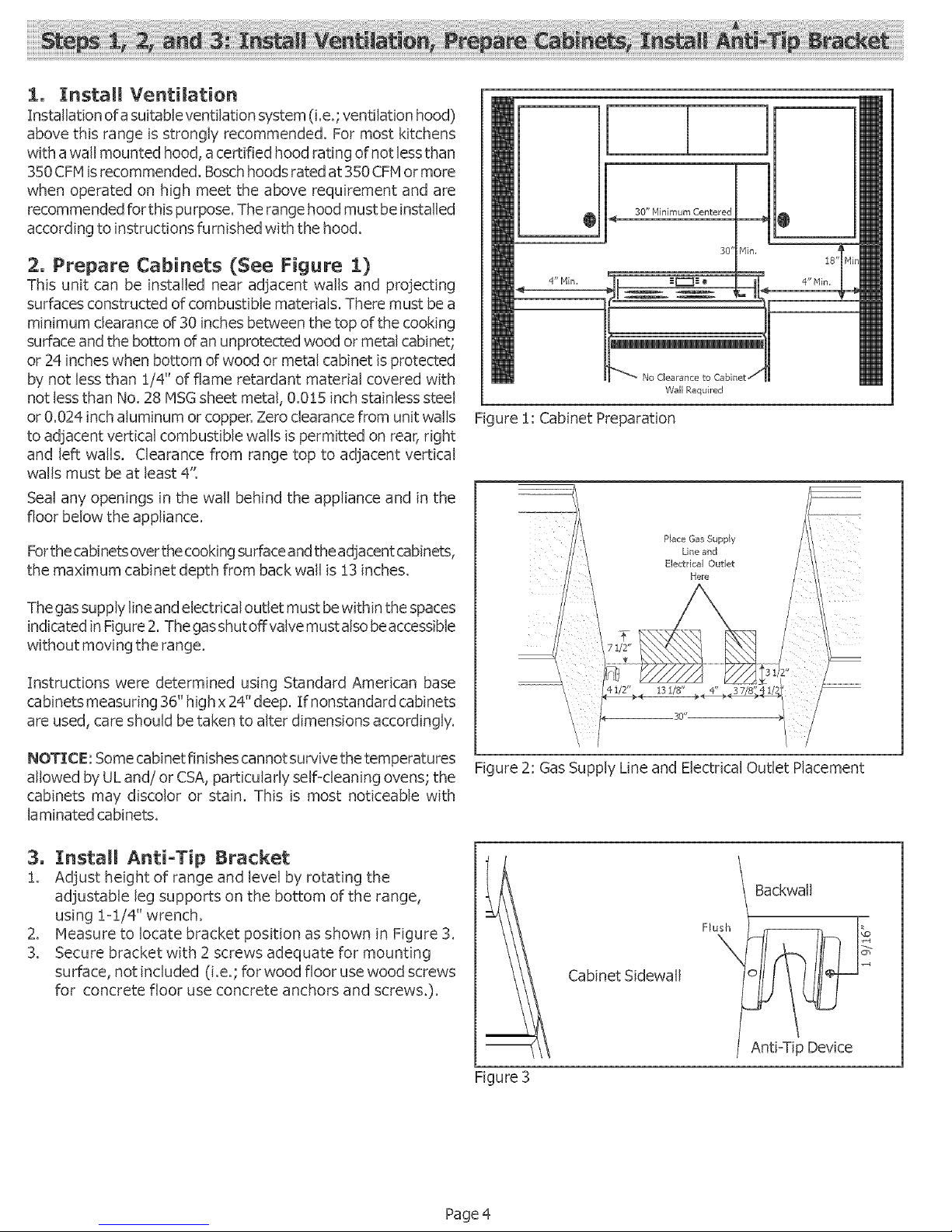
2, Prepare Cabinets (See Figure 1)
This unit can be installed near adjacent walls and projecting
surfaces constructed of combustible materials. There must bea
minimum clearance of 30 inches between the top of the cooking
surface and the bottom of an unprotected wood or metal cabinet;
or 24 inches when bottom of wood or metal cabinet is protected
by not less than 1/4" of flame retardant material covered with
not lessthan No. 28 MSGsheet metal, 0.015 inch stainless steel
or 0.024 inch aluminum or copper, Zero clearance from unit walls
to adjacent vertical combustible walls is permitted on rear, right
and left walls. Clearance from range top to adjacent vertical
walls must be at least 4".
Seal any openings in the wall behind the appliance and in the
floor below the appliance.
Forthe cabinets over the cooking surface and the adjacent cabinets,
the maximum cabinet depth from back wall is 13 inches.
The gassupply line and electrical outlet must be within the spaces
indicated in Figure 2. The gasshutoff valve must also beaccessible
without moving the range.
Instructions were determined using Standard American base
cabinets measuring 36" high x 24" deep. If nonstandard cabinets
are used, care should be taken to alter dimensions accordingly,
NOTIC£: Some cabinet finishes cannot survive the temperatures
allowed by UL and! or CSA, particularly self-cleaning ovens; the
cabinets may discolor or stain, This is most noticeable with
laminated cabinets,
Q
30" Minimum Centered
!
30' P1in,
No Clearance to Cabin
Wall Required
O
18'
4" P1in,
ure 1: Cabinet Preparation
Place Gas Supp}y
Line and
Electrical Outlet
Here
Figure 2: Gas Supply Line and Electrical Outlet Placement
3, ]InstaL! Anti-Tip Bracket
1. Adjust height of range and level by rotating the
adjustable leg supports on the bottom of the range,
using 1-1/4" wrench.
Z Measure to locate bracket position as shown in Figure 3.
3. Secure bracket with 2 screws adequate for mounting
surface, not included (i.e.; for wood floor use wood screws
for concrete floor use concrete anchors and screws0.
Figure 3
Backwall
Cabinet Sidewall
Flush
\
Anti-Tip Device
Page 4
Thegasconnectionislocatedbelowthebackpaneloftherange
(SeeFigure4,Page4). It isaccessiblethroughthewarming
draweraccesspanelorfromthebackof therange.Toreach
accesspanel,removewarmingdrawer.
Shutoffmaingassupplyvalvebeforedisconnectingtheoldrange
andleaveitoffuntilthenewhook-uphasbeencompleted.Don't
forget to reiight thepilot onother gasapplianceswhen
you turn the gas back on.
The range can be installed using rigid pipeor a CSAInternationaF
certified flexible metal appliance connector, If using a flexible
connector, always use a new connector,
Apply pipe joint compound orTeflon* tape appropriate for use
with LP gas and natural gas around all male pipe threads to
prevent leaks.
If not already present, install gas shut-off valve in an easily
accesible location. Make sure all users know where and how to
shut off the gas supply to the range.
Note; The installer should inform the consumer of the
location of the gas shut-off valve,
A CAUTION: Beforeyou plug in an electrical
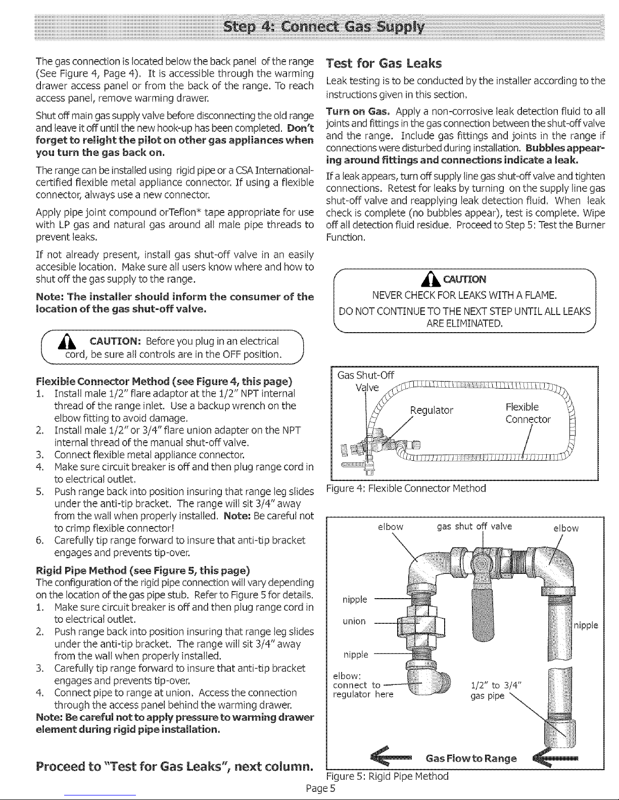
Flexible Connector Method (see Figure 4, this page}
!. Install male :[/2" flare adaptor at the :[/2" NPT internal
thread of the range inlet. Usea backup wrench on the
elbow fitting to avoid damage.
2. Install male 1/2" or 3/4" flare union adapter on the NPT
internal thread of the manual shut-off valve.
3. Connect flexible metal appliance connector.
zk Make sure circuit breaker is off and then plug range cord in
to electrical outlet.
5. Push range back into position insuring that range leg slides
under the anti-tip bracket. The range will sit 3/4" away
from the wall when properly installed. BIote: Be careful not
to crimp flexible connector!
6. Carefully tip range forward to insure that antFtip bracket
engages and prevents tip-over.
Rigid Pipe Method (see Figure S_this page}
The configuration of the rigid pipe connection will vary depending
on the location of the gas pipe stub. Refer to Figure 5 for details.
!. Make sure circuit breaker is off and then plug range cord in
to electrical outlet.
2. Push range back into position insuring that range leg slides
under the anti-tip bracket. The range will sit 3izV'away
from the wall when properly installed.
3. Carefully tip range forward to insure that antFtip bracket
engages and prevents tip-over.
zk Connect pipe to range at union. Access the connection
through the access panel behind the warming drawer.
Note; Be carefut not to apply pressure to warming drawer
element during rigid pipeinstallation.
Test for Gas Leaks
Leak testing isto be conducted by the installer according to the
instructions given in this section.
Turn on Gas. Apply a nomcorrosive leak detection fluid to all
joints and fittings in the gas connection between the shut-off valve
and the range. Include gas fittings and joints in the range if
connections were disturbed during installation. Bubbiesappear o
ing around fittings and connections indicate a Jeak,
If a leak appears, turn off supply line gas shut-off valve and tighten
connections. Retest for leaks by turning on the supply line gas
shut-off valve and reapplying leak detection fluid. When leak
check is complete (no bubbles appear), test is complete. Wipe
off all detection fluid residue. Proceed to Step 5: Test the Burner
Function.
NEVERCHECKFOR LEAKSWITH A FLAME.
O NOT CONTINUE TO THE NEXTSTEPUNTIL ALLLEA
AREELIMINATED.
Gas Shut-Off
Figure 4: Flexible Connector Method
elbow gas shut off valve elbow
\
nipple --
union
nipple
elbow:
connect
regulator here
Proceed to "Test for Gas Leaks'; next columno
Figure 5: Rigid Pipe Method
Page 5
@pie
1. Turn on Power at Breaker
If LCD screen flashes and beeps continuously, the wiring is in=
correctly installed. Verify that wiring in house is correctly in=
stalled. If so, call Bosch Service.
2o Test Rangetop Burners
Test Burner Ignition, Select a rangetop burner knob. Push
down and turn to the flame symbol. The ignitor/spark module
will produce aclicking sound. Once the air has been purged from
the supply lines, the burner should light within four (4) seconds.
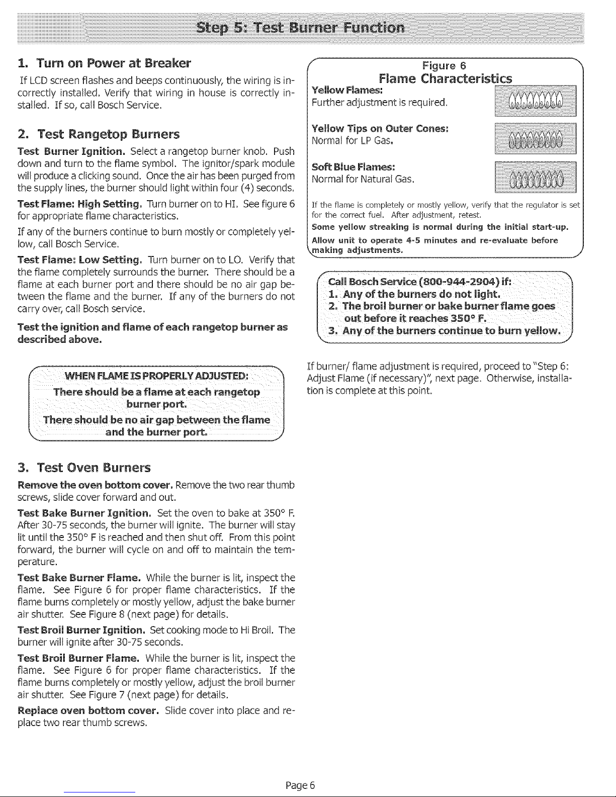
Test Flame: High Se_:ing, Turn burner on to HL Seefigure 6
for appropriate flame characteristics.
If any of the burners continue to burn mostly or completely yeF
low, call Bosch Service.
Test Flame: Low Setting, Turn burner on to LO. Verify that
the flame completely surrounds the burner. There should be a
flame at each burner port and there should be no air gap be-
tween the flame and the burner. If any of the burners do not
carry over, call Boschservice.
Test the ignition and _ame of each rangetep burner as
described above,
Figure 6
Flame Characteristics
Yellow FJames:
Further adjustment is required.
Yellow Tips on Outer Cones:
Normal for LP Gas.
Soft Blue Flames:
Normal for Natural Gas.
If the flame is completely or mostly yellow, verify that the regulator is set
for the correct fuel. After adjustment, retest.
Some yellow streaking is normal during the initial startoup.
AHow unit to operate 4o5 minutes and reoevaUuate before
_aking adjustmentso __ .__j
Call BOSChSerWce (80B19_:2904)if: h
1: Any of the burrJers de not light' q
2' The broi! burner or bake burner flame goes
out before it reaches 3SO o F.
'of the burners continue to burn ye|moW,_
if burner/flame adjustment is required, proceed to"Step 6:
Adjust Flame (if necessary)", next page. Otherwise, installa-
tion is complete at this point.
3, Test Oven Burners
Remove the oven boL_em cover. Remove the two rear thumb
screws, slide cover forward and out.
Test Bake Burner Ignition. Set the oven to bake at 350° R
After 30=75 seconds, the burner will ignite. The burner will stay
lit until the 350° F is reached and then shut off. From this point
forward, the burner will cycle on and off to maintain the tem-
perature.
Test Bake Burner Flame. While the burner is lit, inspect the
flame. See Figure 6 for proper flame characteristics. If the
flame burns completely or mostly yellow, adjust the bake burner
air shutter. See Figure 8 (next page) for details.
Test Broil Burner Ignition. Set cooking mode to Hi Broil. The
burner will ignite after 30=75 seconds.
Test Broil Burner Flame. While the burner is lit, inspect the
flame. See Figure 6 for proper flame characteristics. If the
flame burns completely or mostly yellow, adjust the broil burner
air shutter. See Figure 7 (next page) for details.
Replace oven bottom cover. Slide cover into place and re=
place two rear thumb screws.
Page 6
 Loading...