


FS 100
WARNING:
Improper installation, setup, modifi cation, operation or
maintenance of the heating system can cause personal
injury and property damage.
Follow each appliances' instructions precisely.
For assistance or further information, contact a trained
and certifi ed installer, service provider, or the gas
supply company.
In Massachusetts, the boiler must be installed by a
licensed plumber or gas fi tter.
Application drawings in this manual are conceptual only
and do not purport to address all design, installation,
code, or safety considerations.
The diagrams in this manual are for reference use by
code offi cials, designers and licensed installers. It is
expected that installers have adequate knowledge of
national and local codes, as well as accepted industry
practices, and are trained on equipment, procedures,
and applications involved. Drawings are not to scale.
Refer to the boiler, control and module installer manuals
for additional detailed information!
Gas Condensing Wall Hung & Floor Standing Boilers
Bosch
Greenstar & Greenstar FS 100, 151, 131 Combi Boiler
Greenstar & Greenstar FS 57, 79, 100, 131, 151 Regular Boiler
Applications Manual

|
2
Bosch Greenstar Applications Manual
Bosch Thermotechnology Corp.Data subject to change

Applications Manual Bosch Greenstar | 3
Table of Contents
Single Zone Systems 6
System # 1 Greenstar Combi Wall Boiler
Single Zone Baseboard with Standard Thermostat (drycontact only) and FW200 (optional) 6
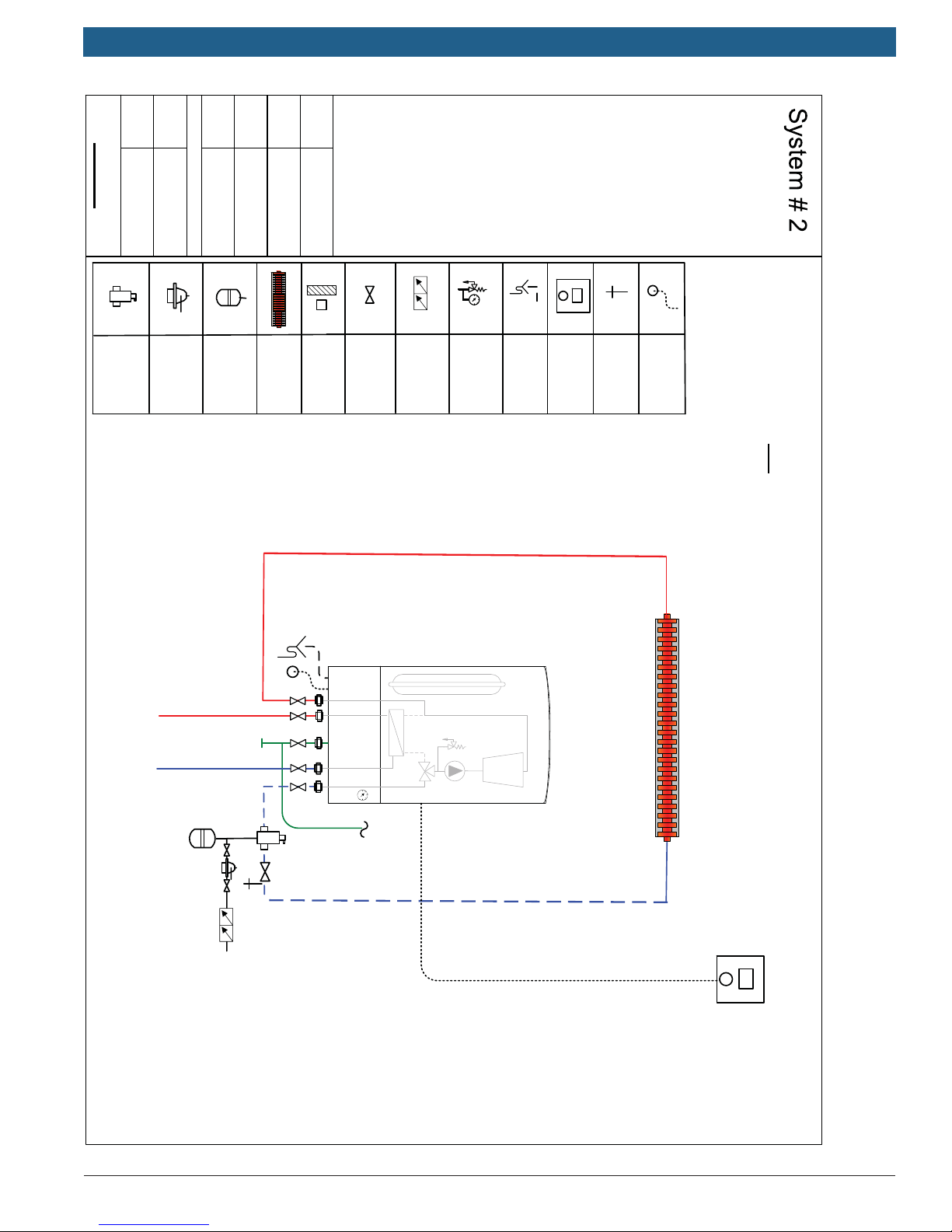
System # 2 Greenstar Combi Wall Boiler
Single Zone Baseboard with Bosch CRC control 8
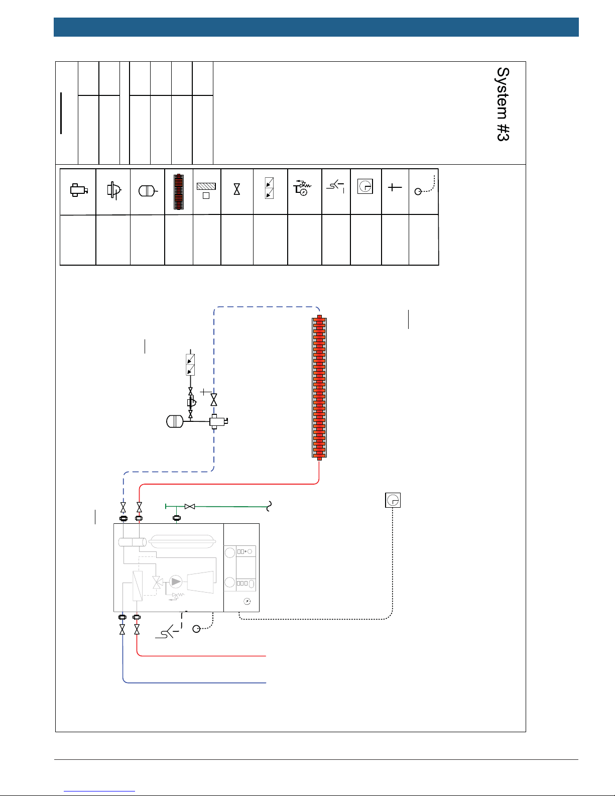
System # 3 Greenstar Combi Floor Boiler
Single Zone Baseboard with Standard Thermostat (dry contact only) 10
System # 4 Greenstar Combi Floor Boiler
Single Zone Baseboard with Bosch CRC control 12
System # 5 Greenstar Heat only Wall Boiler
Single Zone Baseboard with Standard Thermostat (dry contact only) and FW200 (optional) 14
System # 6 Greenstar Heat only Wall Boiler
Single Zone Baseboard with Bosch CRC control 16
System # 7 Greenstar Heat only Floor Boiler
Single Zone Baseboard with Standard Thermostat (dry contact only) 18
System # 8 Greenstar Heat only Floor Boiler
Single Zone Baseboard with Bosch CRC control 20
Multi Zone Systems using Circulators 22
System # 9 Greenstar Combi Wall Boiler
Multi zone system using circulators with standard zone relay (FW200 optional) 22
System # 10 Greenstar Combi Wall Boiler
Multi zone system using circulators and Bosch Comfort Zone Manager (CZM100) 24
System # 11 Greenstar Combi Floor Boiler
Multi zone system using circulators with standard zone relay (FW200 optional) 26
System # 12 Greenstar Combi Floor Boiler
Multi zone system using circulators and Bosch Comfort Zone Manager (CZM100) 28
System # 13 Greenstar Heat only Wall Boiler
Multi zone system using circulators with standard zone relay (FW200 optional) and indirect tank 30
System # 14 Greenstar Heat only Wall Boiler
Multi zone system using circulators and Bosch Comfort Zone Manager (CZM100) and indirect tank 32
System # 15 Greenstar Heat only Floor Boiler
Multi zone system using circulators with standard zone relay (FW200 optional) and indirect tank 34
System # 16 Greenstar Heat only Floor Boiler
Multi zone system using circulators and Bosch Comfort Zone Manager (CZM100) and indirect tank 36
Bosch Thermotechnology Corp.
Data subject to change

|
4
Bosch Greenstar Applications Manual
Multi Zone Systems using Zone Valves 38
System # 17 Greenstar Combi WallBoiler
Multi zone system using zone valves with standard zone relay (FW200 optional) 38
System # 18 Greenstar Combi Wall Boiler
Multi zone system using zone valves and Bosch Comfort Zone Manager (CZM100) 40
System # 19 Greenstar Combi Floor Boiler
Multi zone system using zone valveswith standard zone relay (FW200 optional) 42
System # 20 Greenstar Combi Floor Boiler
Multi zone system using zone valves and Bosch Comfort Zone Manager (CZM100) 44
System # 21 Greenstar Heat Only Wall Boiler
Multi zone system using zone valves with standard zone relay (FW200 optional) and indirect tank 46
System # 22 Greenstar Heat Only Wall Boiler
Multi zone system using zone valves and Bosch Comfort Zone Manager (CZM100) and indirect tank 48
System # 23 Greenstar Heat Only Floor Boiler
Multi zone system using zone valves with standard zone relay (FW200 optional) and indirect tank 50
System # 24 Greenstar Heat Only Floor Boiler
Multi zone system using zone valves and Bosch Comfort Zone Manager (CZM100) and indirect tank 52
Single & Multi Zone Systems using Bosch Control 54
System # 25 Greenstar Combi Wall Boiler
Single zone baseboard with Bosch Control 54
System # 26 Greenstar Combi Floor Boiler
Single zone baseboard with Bosch Control 56
System # 27 Greenstar Heat Only Wall Boiler
Single zone baseboard with Bosch Control 58
System # 28 Greenstar Heat Only Floor Boiler
Single zone system with Bosch Control 60
System # 29 Greenstar Heat Only Wall Boiler
Single zone system with Bosch Control and indirect tank 62
System # 30 Greenstar Combi Wall Boiler
Multi zone system using circulators and Bosch Control with standard zone relay 64
Appendices 66
Appendix A Comfort Room Controller (CRC100) Quick set-up guide 66
Appendix B Primary/Secondary Piping requirements for Greenstar Wall Boiler 68
Appendix C FW200 Quick Set-up Guide 69
Appendix D Wiring of Hydro-Level Low Water Cut-off for Greenstar Wall Boiler 71
Appendix E Wiring of Hydro-Level Low Water Cut-off for Greenstar Floor Boiler 72
Bosch Thermotechnology Corp.Data subject to change
Applications Manual Bosch Greenstar | 5
Explanation Of Symbols
Key To Symbols
Warnings
Warnings in this document are identifi ed by a
warning triangle printed against a grey background.
Keywords at the start of a warning indicate the
type and seriousness of the ensuing risk if meas-
The following keywords are defi ned and can be used in
this document:
DANGER indicates a hazardous situation which, if not
avoided, will result in death or serious injury.
WARNING indicates a hazardous situation which, if
not avoided, could result in death or serious injury.
CAUTION indicates a hazardous situation which, if not
avoided, could result in minor to moderate injury.
NOTICE is used to address practices not related to
personal injury.
Important information
This symbol indicates important information where
there is no risk to people or property.
Bosch Thermotechnology Corp.
Data subject to change
|
6
Bosch Greenstar Applications Manual
State
Bosch
Eliminator
Air
No. .
Auto-Fill
Bases
Expansion
Tank
Changed
Baseboard
Released
air sensor
Created
Outdoor
information.
pressure gauge
Back-flow
preventer
Isolation
valve
Relief valve &
drain
Condensate
Thermostat
Room
Drain
Purge
On/off Tstat
Relief piping
PRV
alternate flow rates.
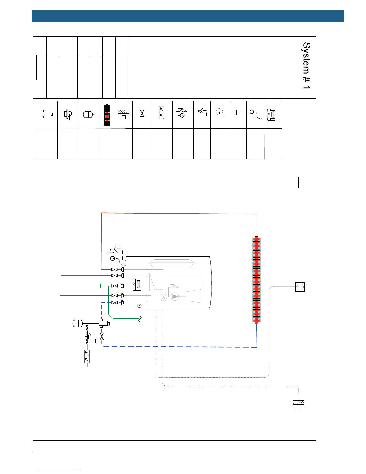
Single Zone
Combi Wall Boiler
Baseboard
FW200
can support a single zone loop
not to exceed 4 gpm at 12 feet of
head. See pump curves in
manual for pump capacities at
Note:Greenstar Internal circulator
DISCLAIMER: Application drawings
in this manual are conceptual only
and do not purport to address all
design, installation, code, or safety
considerations. The diagrams in
this manual are for reference use by
code officials, designers and
licensed installers. It is expected
that installers have adequate
knowledge of national and local
codes, as well as accepted industry
practices, and are trained on
equipment, procedures, and
applications involved. Drawings are
not to scale. Refer to the boiler,
control and module installer
manuals for additional detailed
Hot Water
Domestic
Cold Water
Domestic
Supply
Gas
(Use of FW200 and
outdoor air sensor
is optional)
Bosch Thermotechnology Corp.Data subject to change
Applications Manual Bosch Greenstar | 7
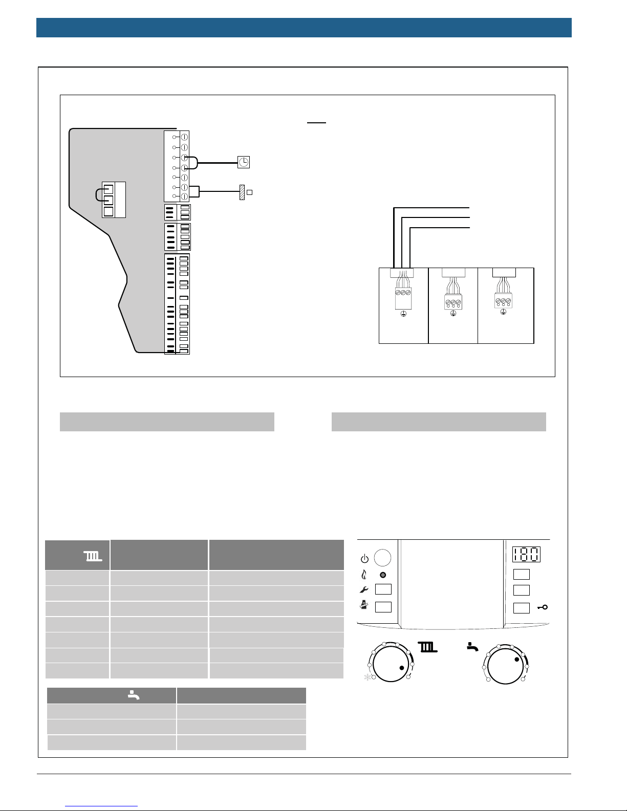
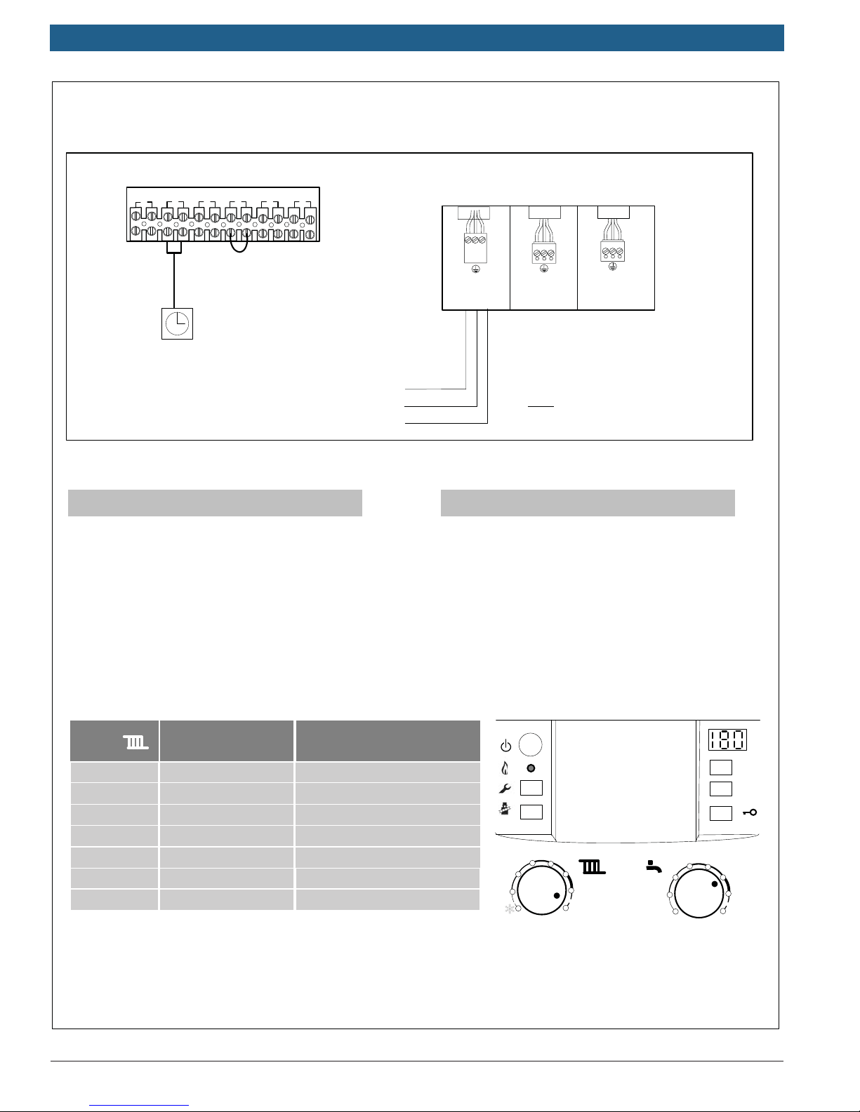
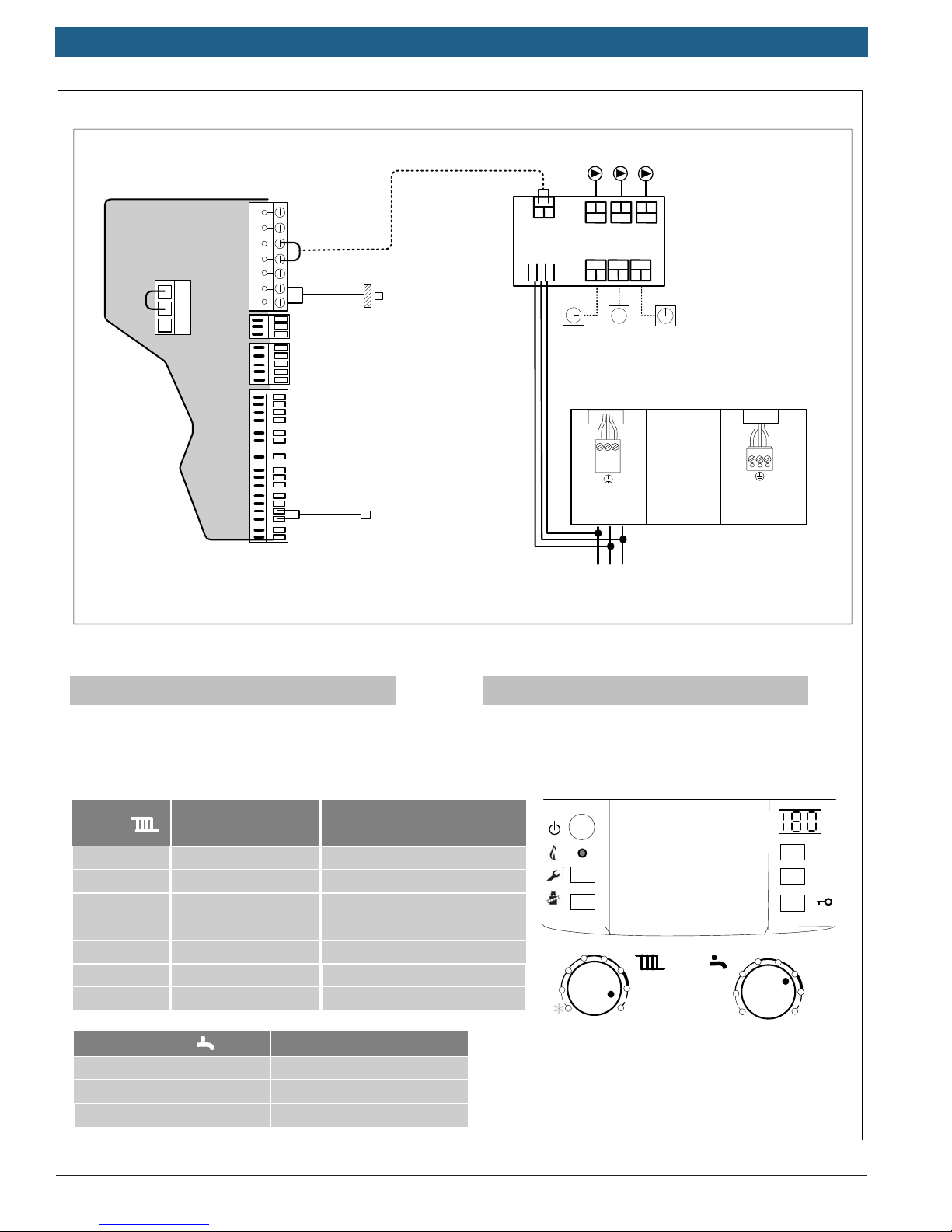
System #1
Heatronic Internal Wiring
Note: For Low Water Cutoff Wiring see
Appendix D of this manual
N
L
white
mains
120v/60 hz
N
L
red
storage
tank pump
120 Vac Supply
Ground
Neutral
N
L
black
ch pump
for unmixed heating
(Not Used)
9
8
7
Bosch Controls
Dry contacts
Outdoor
Sensor
LWCO
DHW Sensor
Supply Sensor
B
B
4
2
1
A
F
Room Thermostat
Outdoor Sensor
If using FW200 (Optional):
Ź install FW200 on front of
boiler (see manual)
Ź install outdoor air sensor
Ź Follow FW200 Quick
Set-up guide in Appendix C
Wiring:
Low Voltage
Ź Remove factory jumper from terminal #2 & #4
inside Heatronic control and connect non-power
robbing thermostat (dry contacts only)
If using FW200 (Optional):
Ź install FW200 on front of boiler (see manual)
Ź install outdoor air sensor
Ź Follow FW200 Quick Set-up guide in Greenstar
Manual
Heatronic Settings:
Boiler
Heating
Dial
1
2
3
4
5
6
max Approx. 194 °F (90°C)
DHW thermostat
min
e
max
Typical supply
temperatures
approx. 95 °F (35 °C)
approx. 109 °F (43 °C)
approx. 122 °F (50 °C)
approx. 140 °F (60 °C)
approx. 153 °F (67 °C)
approx. 167 °F (75 °C)
Typical DHW temperatures
approx. 104 °F (40 °C)
approx. 122 °F (50 °C)
approx. 140 °F (60 °C)
Application
Frost protection
Radiant floor heating
Panel radiator system
Cast Iron radiator system
Baseboard & convector system
External Boiler Junction box
Line Voltage
Ź Wire Main power supply (120 v) to White molex
2
1
34
5
6
max
34
2
1
reset
eco
e
6
max
Bosch Thermotechnology Corp.
Data subject to change
|
8
Bosch Greenstar Applications Manual
State
Bosch
Eliminator
Air
No. .
Auto-Fill
Bases
Expansion
Tank
Changed
Baseboard
Released
02/20/15
air sensor
Created
TK
Outdoor
information.
Bosch
pressure gauge
Back-flow
preventer
Isolation
valve
Relief valve &
Condensate
Controller
Comfort
Purge
Drain
drain
Room
NSC Controls
Relief piping
PRV
manual for pump capacities at
alternate flow rates.
Single zone
Combi wall boiler
Baseboard
can support a single zone loop
not to exceed 4 gpm at 12 feet of
head. See pump curves in
Note:Greenstar Internal circulator
DISCLAIMER: Application drawings
in this manual are conceptual only
and do not purport to address all
design, installation, code, or safety
considerations. The diagrams in
this manual are for reference use by
code officials, designers and
licensed installers. It is expected
that installers have adequate
knowledge of national and local
codes, as well as accepted industry
practices, and are trained on
equipment, procedures, and
applications involved. Drawings are
not to scale. Refer to the boiler,
control and module installer
manuals for additional detailed
Hot Water
Domestic
Cold Water
Domestic
Supply
Gas
Bosch
CRC100 or
CRC200
Bosch Thermotechnology Corp.Data subject to change
Applications Manual Bosch Greenstar | 9
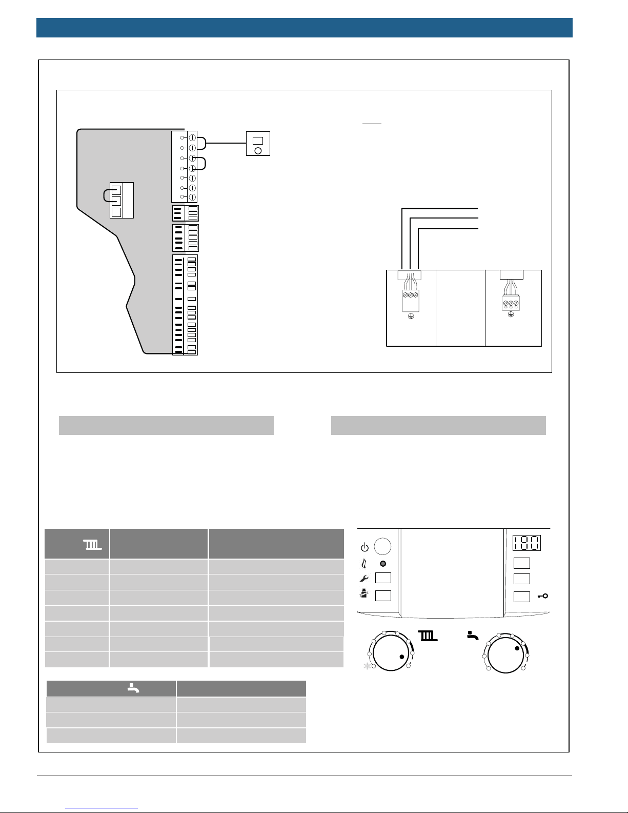
System #2
Heatronic Internal Wiring
Note: For Low Water Cutoff Wiring see
Appendix D of this manual
120 Vac Supply
Ground
Neutral
N
L
white
mains
120v/60 hz
L
black
ch pump
for unmixed heating
(Not Used)
External Boiler Junction box
N
9
8
7
Bosch Controls
Dry contacts
Outdoor
Sensor
LWCO
DHW Sensor
Supply Sensor
CRC100 or CRC200
B
B
4
2
1
A
F
Bosch
Wiring:
Low Voltage
Ź Wire Comfort Room Controller (CRC100 or
CRC200) to Terminals B B of Heatronic control
Ź See Appendix A for Room Controller Settings
Heatronic Settings:
Boiler
Heating
Dial
1
2
3
4
5
6
max Approx. 194 °F (90°C)
DHW thermostat
min
e
max
Typical supply
temperatures
approx. 95 °F (35 °C)
approx. 109 °F (43 °C)
approx. 122 °F (50 °C)
approx. 140 °F (60 °C)
approx. 153 °F (67 °C)
approx. 167 °F (75 °C)
Typical DHW temperatures
approx. 104 °F (40 °C)
approx. 122 °F (50 °C)
approx. 140 °F (60 °C)
Application
Frost protection
Radiant floor heating
Panel radiator system
Cast Iron radiator system
Baseboard & convector system
Line Voltage
Ź Wire Main power supply (120 v) to White molex
2
1
34
5
6
max
34
2
1
reset
eco
e
6
max
Bosch Thermotechnology Corp.
Data subject to change
|
10
Bosch Greenstar Applications Manual
State
Bosch
Eliminator
Air
Bases
No. .
Auto-Fill
expansion tank in combi boiler
standard systems -see boiler
models may be adequate for
manual for details.
Changed
Baseboard
Expansion
Tank
Note: additional expansion
tank shown – internal
Released
Created
air sensor
Outdoor
information.
pressure gauge
Isolation
valve
Back-flow
preventer
Relief valve &
drain
Thermostat
Condensate
alternate flow rates.
Room
manual for pump capacities at
head. See pump curves in
Purge
Drain
can support a single zone loop
not to exceed 4 gpm at 12 feet of
On/off Thermostat
Relief piping
PRV
Note:Greenstar Internal circulator
Single Zone
Combi floor boiler
Baseboard
DISCLAIMER: Application drawings
in this manual are conceptual only
and do not purport to address all
design, installation, code, or safety
considerations. The diagrams in
this manual are for reference use by
code officials, designers and
licensed installers. It is expected
that installers have adequate
knowledge of national and local
codes, as well as accepted industry
practices, and are trained on
equipment, procedures, and
applications involved. Drawings are
not to scale. Refer to the boiler,
control and module installer
manuals for additional detailed
Header in closed position
Note: Internal Low Loss
Supply
Gas
Hot Water
Domestic
Cold Water
Domestic
Bosch Thermotechnology Corp.Data subject to change

Applications Manual Bosch Greenstar | 11
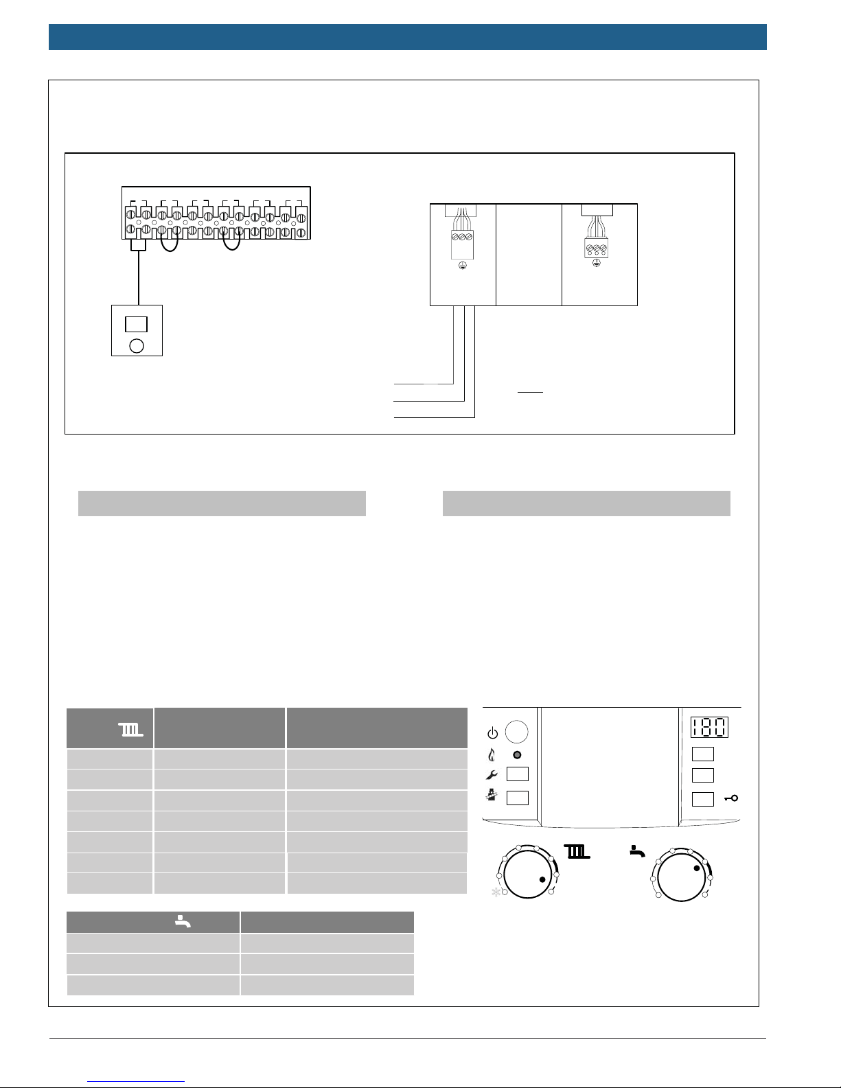
System #3
Low Voltage Wiring Line Voltage Wiring
BUS
out sen
TT
3 4
2
1
LWCO
DHW sen
5 6
Room
Thermostat
Wiring:
Low Voltage
Ź Remove factory jumper from terminal #2 and
connect non-power robbing thermostat (dry contacts
only) to terminal #2
120 V Line
Ground
Neutral
N
N
L
white
mains
120v/60 hz
L
black
ch pump
for unmixed heating
(Not Used)
Note: For Low Water Cutoff Wiring see
Appendix E of this manual
Line Voltage
Ź Wire Main power supply (120 v) to White molex
Heatronic Settings:
Boiler
Heating
Dial
1
2
3
4
5
6
max Approx. 194 °F (90°C)
DHW thermostat
min
e
max
Bosch Thermotechnology Corp.
Typical supply
temperatures
approx. 95 °F (35 °C)
approx. 109 °F (43 °C)
approx. 122 °F (50 °C)
approx. 140 °F (60 °C)
approx. 153 °F (67 °C)
approx. 167 °F (75 °C)
Typical DHW temperatures
approx. 104 °F (40 °C)
approx. 122 °F (50 °C)
approx. 140 °F (60 °C)
Application
Frost protection
Radiant floor heating
Panel radiator system
Cast Iron radiator system
Baseboard & convector system
2
1
34
5
max
34
2
6
1
Data subject to change
reset
eco
e
6
max

|
12
Bosch Greenstar Applications Manual
State
Bosch
Eliminator
Air
No. .
Auto-Fill
Bases
Expansion
Tank
standard systems -see boiler
models may be adequate for
manual for details.
Changed
Released
Created
information.
Baseboard
expansion tank in combi boiler
Note: additional expansion
tank shown – internal
Isolation
valve
manuals for additional detailed
Bosch
pressure gauge
Back-flow
preventer
Relief valve &
Condensate
Controller
Comfort
Sensor
alternate flow rates.
Supply
manual for pump capacities at
head. See pump curves in
drain
Room
Drain
Purge
not to exceed 4 gpm at 12 feet of
Relief piping
Note:Greenstar Internal circulator
can support a single zone loop
NSC Controls
PRV
Single Zone
Combi floor boiler
Baseboard
DISCLAIMER: Application drawings
in this manual are conceptual only
and do not purport to address all
design, installation, code, or safety
considerations. The diagrams in
this manual are for reference use by
code officials, designers and
licensed installers. It is expected
that installers have adequate
knowledge of national and local
codes, as well as accepted industry
practices, and are trained on
equipment, procedures, and
applications involved. Drawings are
not to scale. Refer to the boiler,
control and module installer
Header in closed position
Note
: Internal Low Loss
Supply
Gas
Hot Water
Domestic
Cold Water
Domestic
CRC100 or CRC200
Bosch
Bosch Thermotechnology Corp.Data subject to change
Applications Manual Bosch Greenstar | 13
System #4
Low Voltage Wiring Line Voltage Wiring
BUS
1
Bosch
CRC100 or CRC200
out sen
TT
3 4
2
LWCO
DHW sen
5 6
Wiring:
Low Voltage
Ź Wire Comfort Room Controller (CRC100 or
CRC200) to Terminal # 1 on back of Greenstar FS
Boiler
120 V Line
Ground
Neutral
N
N
L
white
mains
120v/60 hz
L
black
ch pump
for unmixed heating
(Not Used)
Note: For Low Water Cutoff Wiring see
Appendix E of this manual
Line Voltage
Ź Wire Main power supply (120 v) to White molex
Ź See Appendix A for Room Controller Settings
Heatronic Settings:
Boiler
Heating
Dial
1
2
3
4
5
6
max Approx. 194 °F (90°C)
DHW thermostat
min
e
max
Typical supply
temperatures
approx. 95 °F (35 °C)
approx. 109 °F (43 °C)
approx. 122 °F (50 °C)
approx. 140 °F (60 °C)
approx. 153 °F (67 °C)
approx. 167 °F (75 °C)
Typical DHW temperatures
approx. 104 °F (40 °C)
approx. 122 °F (50 °C)
approx. 140 °F (60 °C)
Application
Frost protection
Radiant floor heating
Panel radiator system
Cast Iron radiator system
Baseboard & convector system
2
1
34
5
max
reset
eco
34
2
6
1
e
6
max
Bosch Thermotechnology Corp.
Data subject to change
|
14
Bosch Greenstar Applications Manual
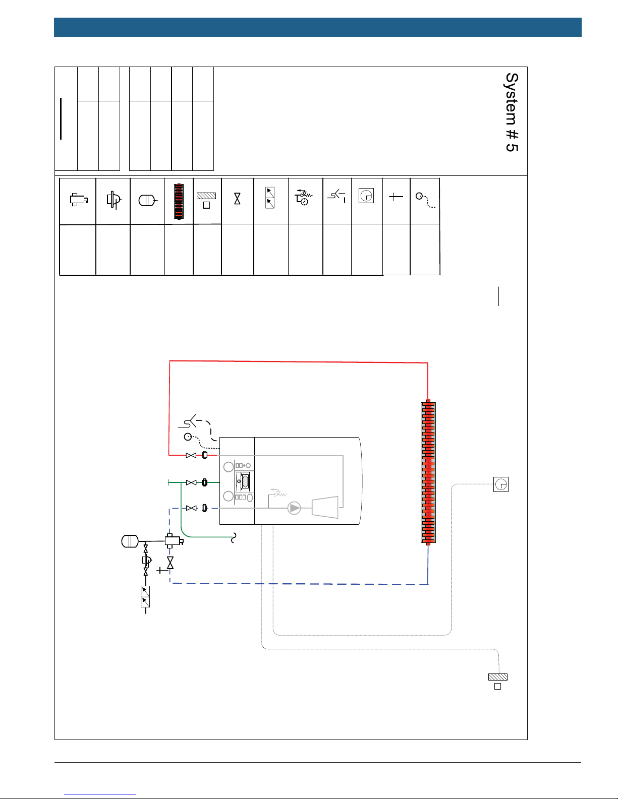
Single Zone
Heat only wall boiler
Baseboard
State
No. .
Bases
Changed
Released
Created
DISCLAIMER: Application drawings
in this manual are conceptual only
and do not purport to address all
design, installation, code, or safety
considerations. The diagrams in
this manual are for reference use by
code officials, designers and
licensed installers. It is expected
that installers have adequate
knowledge of national and local
codes, as well as accepted industry
practices, and are trained on
equipment, procedures, and
applications involved. Drawings are
not to scale. Refer to the boiler,
control and module installer
manuals for additional detailed
information.
On/off Thermostat
Bosch
Eliminator
Air
TK
02/20/15
pressure gauge
Auto-Fill
Expansion
Tank
air sensor
Baseboard
Isolation
Outdoor
valve
Back-flow
preventer
Relief valve &
drain
Thermostat
Condensate
Room
Purge
Drain
Relief piping
PRV
head. See pump curves in
manual for pump capacities at
alternate flow rates.
Note:Greenstar Internal circulator
can support a single zone loop
not to exceed 4 gpm at 12 feet of
Supply
Gas
is optional)
outdoor air sensor
(Use of FW200 and
Bosch Thermotechnology Corp.Data subject to change
Applications Manual Bosch Greenstar | 15
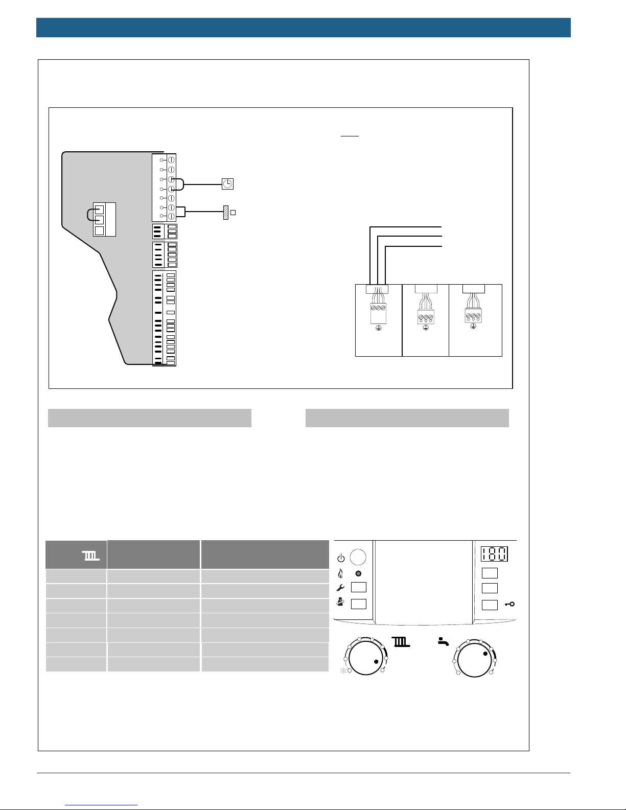
System #5
Heatronic Internal Wiring
Bosch Controls
Dry contacts
9
Outdoor
Sensor
8
LWCO
7
DHW Sensor
Supply Sensor
Wiring:
Low Voltage
Note: For Low Water Cutoff Wiring see
Appendix D of this manual
B
B
4
2
1
A
F
Room Thermostat
Outdoor Sensor
If using FW200 (Optional):
120 Vac Supply
Ground
Neutral
Ź install FW200 on front of
boiler (see manual)
Ź install outdoor air sensor
Ź Follow FW200 Quick
Set-up guide in Appendix C
N
N
L
white
mains
120v/60 hz
L
red
storage
tank pump
N
L
black
ch pump
for unmixed heating
(Not Used)
External Boiler Junction box
Line Voltage
Ź Remove factory jumper from terminal #2 & #4
inside Heatronic control and connect non-power
robbing thermostat (dry contacts only)
Heatronic Settings:
Boiler
Heating
Dial
1
2
3
4
5
6
max Approx. 194 °F (90°C)
Typical supply
temperatures
approx. 95 °F (35 °C)
approx. 109 °F (43 °C)
approx. 122 °F (50 °C)
approx. 140 °F (60 °C)
approx. 153 °F (67 °C)
approx. 167 °F (75 °C)
Application
Frost protection
Radiant floor heating
Panel radiator system
Cast Iron radiator system
Baseboard & convector system
Ź Wire Main power supply (120 v) to White molex
2
1
34
5
6
max
2
1
34
e
max
reset
eco
6
Bosch Thermotechnology Corp.
Data subject to change
|
16
Bosch Greenstar Applications Manual
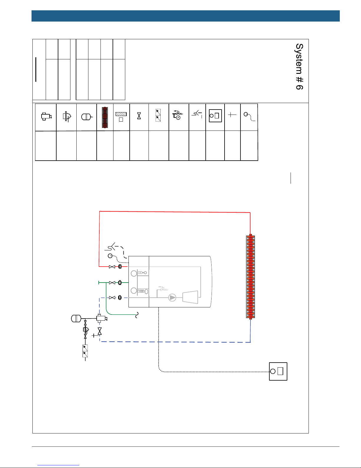
Single Zone
Heat only wall boiler
Baseboard
State
No. .
Bases
Changed
Released
Created
DISCLAIMER: Application drawings
in this manual are conceptual only
and do not purport to address all
design, installation, code, or safety
considerations. The diagrams in
this manual are for reference use by
code officials, designers and
licensed installers. It is expected
that installers have adequate
knowledge of national and local
codes, as well as accepted industry
practices, and are trained on
equipment, procedures, and
applications involved. Drawings are
not to scale. Refer to the boiler,
control and module installer
manuals for additional detailed
information.
NSC Controls
Bosch
Eliminator
Air
Auto-Fill
TK
02/20/15
Bosch
pressure gauge
Expansion
Tank
Outdoor
valve
air sensor
Baseboard
Isolation
preventer
Back-flow
Relief valve &
drain
Condensate
Control
Comfort
Room
Purge
Drain
Relief piping
PRV
manual for pump capacities at
alternate flow rates.
can support a single zone loop
not to exceed 4 gpm at 12 feet of
head. See pump curves in
Note:Greenstar Internal circulator
Supply
Gas
CRC200
Bosch Thermotechnology Corp.Data subject to change
Bosch
CRC100 or
Applications Manual Bosch Greenstar | 17
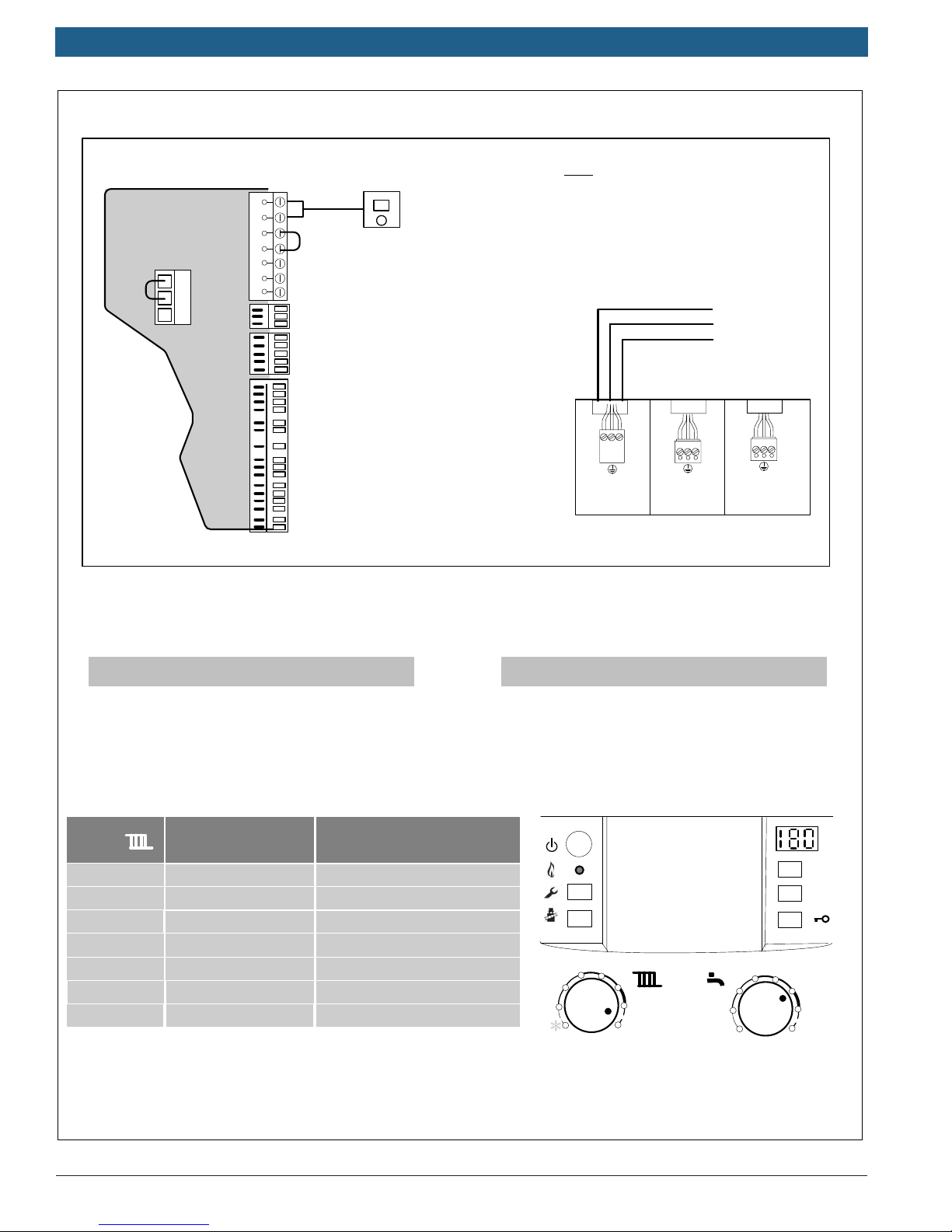
System #6
Heatronic Internal Wiring
Outdoor
Sensor
B
B
4
2
1
A
F
9
8
7
Bosch Controls
Dry contacts
LWCO
DHW Sensor
Supply Sensor
CRC100 or CRC200
Bosch
Note: For Low Water Cutoff Wiring see
Appendix D of this manual
120 Vac Supply
Ground
Neutral
N
N
L
white
mains
120v/60 hz
L
red
storage
tank pump
N
L
black
ch pump
for unmixed heating
(Not Used)
External Boiler Junction box
Wiring:
Low Voltage
Ź Wire Comfort Room Controller (CRC100 or
CRC200) to Terminals B B of Heatronic control
Ź See Appendix A for Room Controller Settings
Heatronic Settings:
Boiler
Heating
Dial
1
2
3
4
5
6
max Approx. 194 °F (90°C)
Typical supply
temperatures
approx. 95 °F (35 °C)
approx. 109 °F (43 °C)
approx. 122 °F (50 °C)
approx. 140 °F (60 °C)
approx. 153 °F (67 °C)
approx. 167 °F (75 °C)
Application
Frost protection
Radiant floor heating
Panel radiator system
Cast Iron radiator system
Baseboard & convector system
Line Voltage
Ź Wire Main power supply (120 v) to White molex
2
1
34
5
6
max
34
2
1
reset
eco
e
6
max
Bosch Thermotechnology Corp.
Data subject to change

|
18
Bosch Greenstar Applications Manual
State
Bosch
Eliminator
Air
No. .
Auto-Fill
Bases
Expansion
Tank
Changed
Baseboard
Released
air sensor
Created
Outdoor
information.
manuals for additional detailed
valve
DISCLAIMER: Application drawings
in this manual are conceptual only
and do not purport to address all
design, installation, code, or safety
considerations. The diagrams in
this manual are for reference use by
code officials, designers and
licensed installers. It is expected
that installers have adequate
knowledge of national and local
codes, as well as accepted industry
practices, and are trained on
equipment, procedures, and
applications involved. Drawings are
not to scale. Refer to the boiler,
control and module installer
pressure gauge
Isolation
Back-flow
preventer
Relief valve &
drain
Thermostat
Condensate
Room
alternate flow rates.
manual for pump capacities at
Drain
head. See pump curves in
Purge
can support a single zone loop
not to exceed 4 gpm at 12 feet of
On/Off Thermostat
Relief piping
PRV
Note:Greenstar Internal circulator
Single Zone
Heat only floor boiler
Baseboard
Header in closed position
Note: Internal Low Loss
Supply
Gas
Bosch Thermotechnology Corp.Data subject to change
Applications Manual Bosch Greenstar | 19
System #7
Low Voltage Wiring Line Voltage Wiring
BUS
out sen
TT
3 4
2
1
LWCO
DHW sen
5 6
Room
Thermostat
Wiring:
Low Voltage
Ź Remove factory jumper from terminal #2 and
connect non-power robbing thermostat (dry contacts
only) to terminal #2
120 V Line
Ground
Neutral
N
N
L
white
mains
120v/60 hz
N
L
red
storage
tank pump
L
black
ch pump
for unmixed heating
(Not Used)
Note: For Low Water Cutoff Wiring see
Appendix E of this manual
Line Voltage
Ź Wire Main power supply (120 v) to White molex
Heatronic Settings:
Boiler
Heating
Dial
1
2
3
4
5
6
max Approx. 194 °F (90°C)
Bosch Thermotechnology Corp.
Typical supply
temperatures
approx. 95 °F (35 °C)
approx. 109 °F (43 °C)
approx. 122 °F (50 °C)
approx. 140 °F (60 °C)
approx. 153 °F (67 °C)
approx. 167 °F (75 °C)
Application
Frost protection
Radiant floor heating
Panel radiator system
Cast Iron radiator system
Baseboard & convector system
2
1
34
reset
eco
5
6
max
2
1
34
e
6
max
Data subject to change
|
20
Bosch Greenstar Applications Manual
State
Bosch
Eliminator
Air
No. .
Auto-Fill
Bases
Expansion
Tank
Changed
Baseboard
Released
air sensor
Created
Outdoor
information.
manuals for additional detailed
valve
DISCLAIMER: Application drawings
in this manual are conceptual only
and do not purport to address all
design, installation, code, or safety
considerations. The diagrams in
this manual are for reference use by
code officials, designers and
licensed installers. It is expected
that installers have adequate
knowledge of national and local
codes, as well as accepted industry
practices, and are trained on
equipment, procedures, and
applications involved. Drawings are
not to scale. Refer to the boiler,
control and module installer
pressure gauge
Back-flow
preventer
Isolation
Relief valve &
Thermostat
Condensate
drain
Room
manual for pump capacities at
alternate flow rates.
Purge
Drain
can support a single zone loop
not to exceed 4 gpm at 12 feet of
head. See pump curves in
Note:Greenstar Internal circulator
NSC Controls
Relief piping
PRV
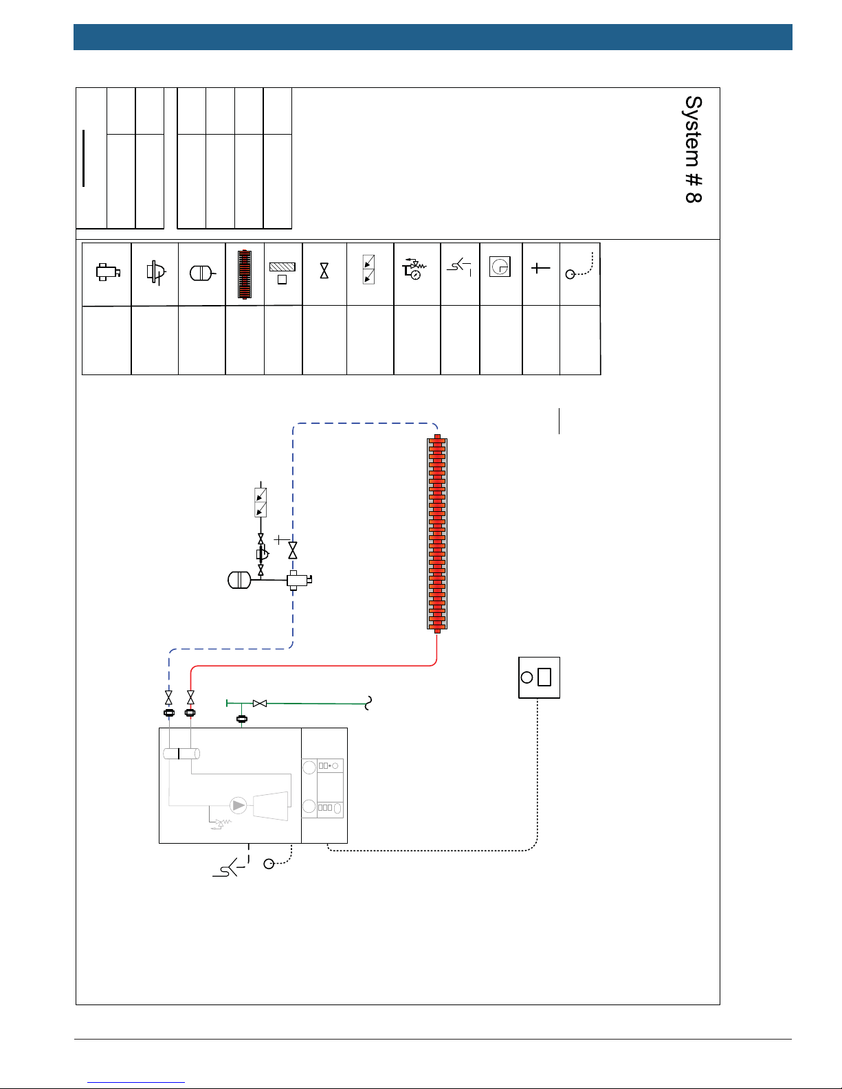
Single Zone
Heat only floor boiler
Baseboard
Header in closed position
Note: Internal Low Loss
Supply
Gas
CRC100 or CRC200
Bosch
Bosch Thermotechnology Corp.Data subject to change
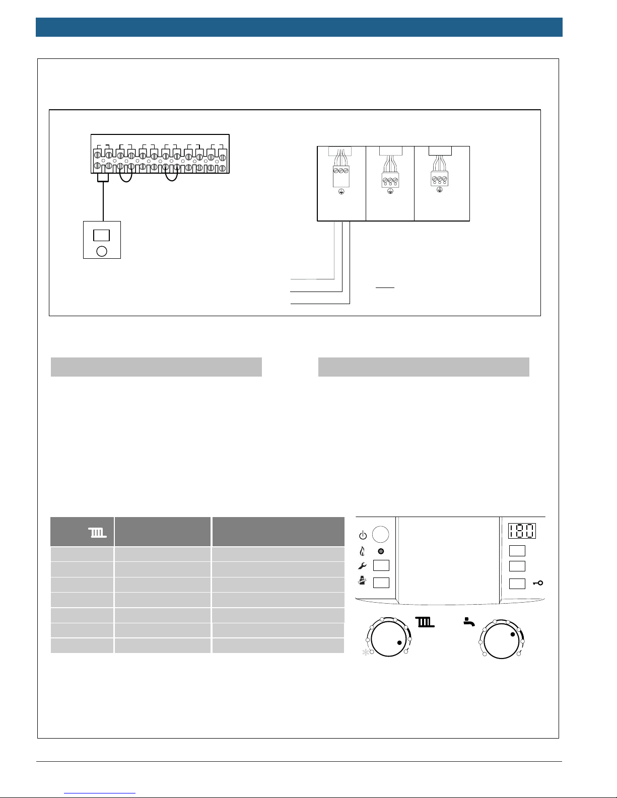
Applications Manual Bosch Greenstar | 21
System #8
Low Voltage Wiring Line Voltage Wiring
BUS
1
Bosch
CRC100 or CRC200
out sen
TT
3 4
2
LWCO
DHW sen
5 6
Wiring:
Low Voltage
Ź Wire Comfort Room Controller (CRC100 or
CRC200) to Terminal # 1 on back of Greenstar FS
Boiler
120 V Line
Ground
Neutral
N
N
L
white
mains
120v/60 hz
N
L
red
storage
tank pump
L
black
ch pump
for unmixed heating
(Not Used)
Note: For Low Water Cutoff Wiring see
Appendix E of this manual
Line Voltage
Ź Wire Main power supply (120 v) to White molex
Ź See Appendix A for Room Controller Settings
Heatronic Settings:
Boiler
Heating
Dial
1
2
3
4
5
6
max Approx. 194 °F (90°C)
Typical supply
temperatures
approx. 95 °F (35 °C)
approx. 109 °F (43 °C)
approx. 122 °F (50 °C)
approx. 140 °F (60 °C)
approx. 153 °F (67 °C)
approx. 167 °F (75 °C)
Application
Frost protection
Radiant floor heating
Panel radiator system
Cast Iron radiator system
Baseboard & convector system
2
1
34
reset
eco
5
6
max
2
1
34
e
6
max
Bosch Thermotechnology Corp.
Data subject to change
|
22
Bosch Greenstar Applications Manual
Date
Bosch
Outdoor
Sensor
...
No.
Sensor
Bases
Changed
Released
Created
Circulator
Supply
Shut-off
preventer
valve
control and module installer
manuals for additional detailed
information.
PRV Relief
Back-flow
Piping
not to scale. Refer to the boiler,
applications involved. Drawings are
equipment, procedures, and
Expansion Tank
codes, as well as accepted industry
practices, and are trained on
this manual are for reference use by
code officials, designers and
licensed installers. It is expected
that installers have adequate
knowledge of national and local
Thermostat
Room
DISCLAIMER: Application drawings
in this manual are conceptual only
and do not purport to address all
design, installation, code, or safety
considerations. The diagrams in
Condensate
drain
Flow Check
T
T
T
T
...
Air Eliminator
Auto-Fill
Zone Relay
Purge Drain
Heating
zone
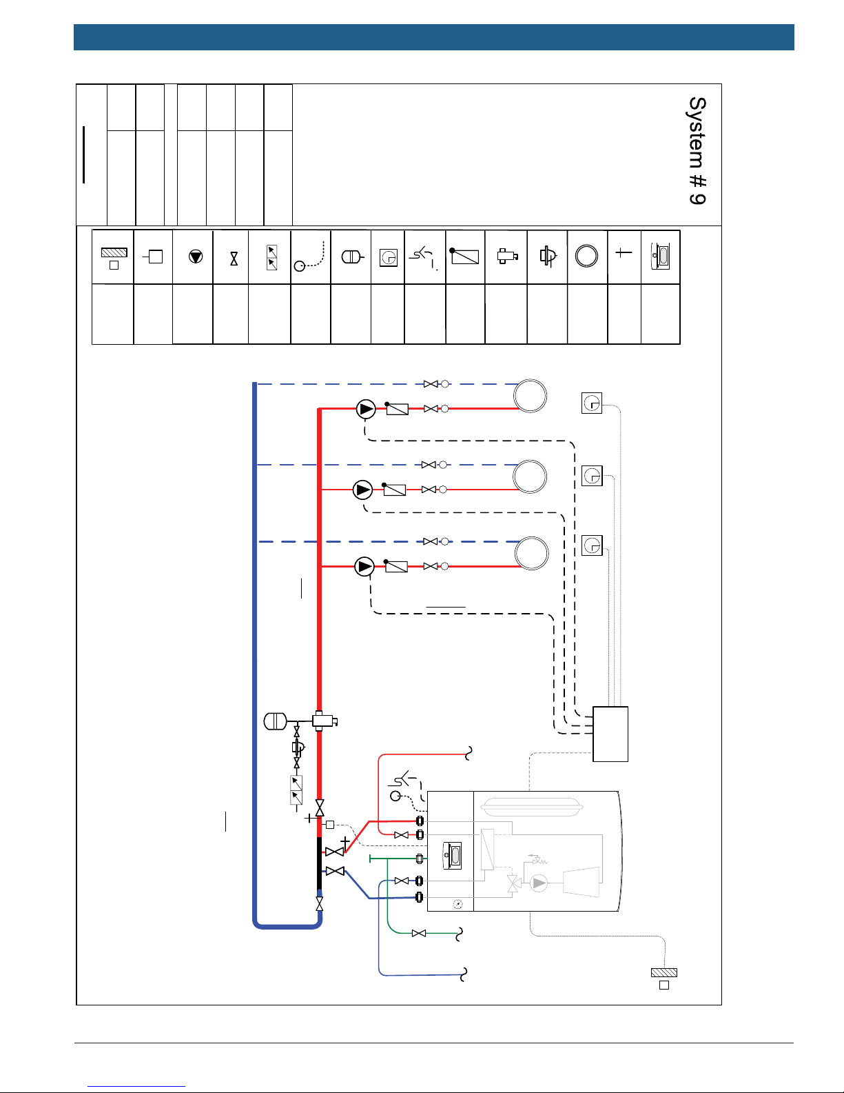
Multi Zone
Combi wall boiler
Circulators
FW200
Primary/Secondary piping
Note: See Appendix B for
requirements
boiler – see manual for details.
expansion tank external to the
may require an additional
Note: Larger heating systems
T
T
Zone relay
Hot Water
Domestic
X X
outdoor air sensor is
(Use of FW200 and
optional)
Supply
Gas
Cold Water
Domestic
Bosch Thermotechnology Corp.Data subject to change
Applications Manual Bosch Greenstar | 23
System # 9
Heatronic Internal Wiring
X
X
( end switch )
120 Vac
Power
Zone 1
Zone 1
Zone 2
Zone 2
Zone 3
Zone 3
TTTTTT
9
8
7
Bosch Controls
Dry contacts
Outdoor
Sensor
LWCO
DHW Sensor
B
B
4
2
1
A
F
Outdoor Sensor
If using FW200 (Optional):
Ź install FW200 on front of
boiler (see manual)
Ź install outdoor air sensor
Ź Follow FW200 Quick
Set-up guide in Appendix C
Supply Sensor
Supply Sensor
Note: For Low Water Cutoff Wiring see
Appendix D of this manual
Wiring:
Low Voltage
Ź Remove factory jumper from terminal #2 & #4
and connect to End Switch of Mult-Zone relay (dry
contacts only)
Heatronic Settings:
Boiler
Heating
Dial
1
2
3
4
5
6
max Approx. 194 °F (90°C)
Typical supply
temperatures
approx. 95 °F (35 °C)
approx. 109 °F (43 °C)
approx. 122 °F (50 °C)
approx. 140 °F (60 °C)
approx. 153 °F (67 °C)
approx. 167 °F (75 °C)
Application
Frost protection
Radiant floor heating
Panel radiator system
Cast Iron radiator system
Baseboard & convector system
External Boiler Junction box
N
N
L
white
mains
120v/60 hz
L
NG
120 Vac Supply
L
black
ch pump
for unmixed heating
(Not Used)
Line Voltage
Ź Wire Main power supply (120 v) to White molex
of Boiler external junction box
Ź Wire 120 Vac power supply to zone relay
2
1
34
5
6
max
34
2
1
reset
eco
e
6
max
DHW thermostat
min
e
max
Typical DHW temperatures
approx. 59 °F (15 °C)
approx. 131 °F (55 °C)
approx. 158 °F (70 °C)
Bosch Thermotechnology Corp.
Data subject to change
 Loading...