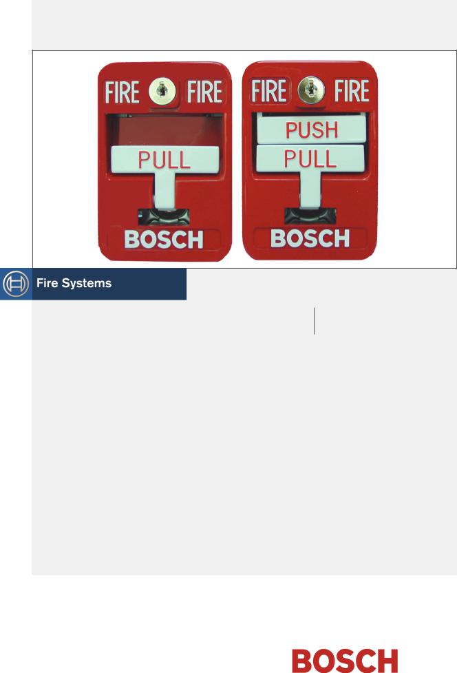
Bosch FMM-462-D, FMM-462 User Manual

FMM-462, FMM-462-D
Installation Instructions
EN Addressable Manual Fire
Alarm Boxes

FMM-462, FMM-462-D | Installation Instructions | 1.0 Description
1.0Description
These instructions cover the installation of Bosch FMM462 (Single Action) and FMM-462-D (Dual Action) Addressable Manual Fire Alarm Box in a fire system supervised by a Bosch Fire Alarm Control Panel (FACP).
Install, test and maintain the FMM-462/FMM-462-D Addressable Manual Fire Alarm Box according to these instructions, NFPA 72, Local Codes and the Authority Having Jurisdiction (AHJ). Failure to follow these instructions can result in failure of the device to operate properly. Bosch is not responsible for improperly installed, tested or maintained devices.
Before installing the FMM-462/FMM-462-D, read through the D9124 Operation and Installation Guide
(P/N: 39352). The FMM-462/FMM-462-D uses Bosch’s Addressable Expansion System for interfacing with a control panel. You should be familiar with this system and the associated equipment prior to installing any devices. You should also be familiar with all applicable local and state codes, ADA requirements and the requirements of the AHJ.
These instructions contain procedures to follow in order to avoid personal injury and damage to equipment.
NFPA 72 requires a complete system-wide functional test be performed following any modifications, repair, upgrades or adjustments made to the system’s components, hardware, wiring, programming and software/firmware.
The Bosch FMM-462/FMM-462-D Addressable Manual Fire Alarm Box is a UL Listed fire alarm initiating device. It can be installed along with other addressable initiating devices on a D9124 data expansion loop.
Attached to the manual fire alarm box is a factoryinstalled POPIT (P/N: 37519). The POPIT module is addressed using on-board slide switches and is then connected to a D9124 data expansion loop. The POPIT is polled every 150 to 300 ms and reports any opens, shorts, or ground faults on the manual fire alarm box wiring.
The FMM-462/FMM-462-D is generally installed at building exits such as stairways or lobbies. Persons evacuating the building during an emergency are able to initiate an alarm by pulling down a lever. The latching pull-down lever on the FMM-462/FMM-462-D requires a key to reset. This allows the origin of the alarm to be determined easily.
The FMM-462/FMM-462-D is a high quality, die cast device constructed entirely of nontoxic materials. It has a low profile and rounded edges to fit most design requirements. All components are pre-painted or have plated surfaces to inhibit corrosion.
The FMM-462/FMM-462-D is compatible with the following Bosch Control Panels: D7212G, D7412G, D9412G, D7112, D7412, D8112, D9412, D7212B, and D9112B.
The FMM-462/FMM-462-D is also compatible with the following Bosch accessories: FMM-BB-R Deep Surface Mount Back Box and FMM-100GR Replacement Glass Rod.
2.0Installation
2.1Wiring
The FMM-462/FMM-462-D Addressable Manual Fire Alarm Box is a single action device with a white pulldown lever in its center. The lever is easily accessible to persons either initiating an alarm or testing the fire alarm system. It also has a built-in break glass rod carrier that holds a standard glass rod. Pulling down the lever latches it in place, breaks the glass rod, and causes a short across the POPIT sensor loop. The alarm is then detected by the D9124 Fire Alarm Control Panel (FACP). The pull-down lever cannot be reset until the correct key is inserted into the lock and the unit is opened. The lever can then be restored to its normal position.
Use the following instructions to install the FMM-462/ FMM-462-D Manual Fire Alarm Box correctly (refer to Figure 1 on page 3).
1)Open the POPIT Module (P/N: 37519) using a small slotted screwdriver.
2)Set the POPIT address using the on-board slide switches. Refer to the D9124 Operation and Installation Guide (P/N: 39352) and the D9124 Program Record Sheet (P/N: 50098) for POPIT addressing information.
3)Strip off approximately 1/4 in. (6.4 mm) of insulation from each data expansion loop wire and insert under the appropriate data terminal.
There are four screw terminals on the circuit board. One is marked positive and another is marked negative. The wires from the data expansion loop connect to these two terminals. The other two terminals are marked sensor loop. Do not remove the wires connecting the manual fire alarm box to the POPIT sensor loop.
2 |
Bosch | 11/04 | F01U001401B |
 Loading...