


 Loading...
Modular Fire Panel
FPA-5000
en Networking Guide

Modular Fire Panel Table of contents | en 3
Table of contents
1 |
Safety instructions |
5 |
2 |
Introduction |
6 |
3 |
Connecting FPA-5000 |
7 |
3.1 |
Networking layers |
7 |
3.2 |
Topologies |
7 |
3.2.1 |
Key |
10 |
3.2.2 |
Ethernet loop |
12 |
3.2.3 |
Ethernet loop with OPC server |
13 |
3.2.4 |
Ethernet loop with OPC server to redundant panel controller |
14 |
3.2.5 |
Ethernet/CAN double loop |
15 |
3.2.6 |
Ethernet backbone with sub-loops (Ethernet/CAN) |
16 |
3.2.7 |
Connecting Ethernet loops |
18 |
3.3 |
Ethernet network |
20 |
3.3.1 |
Protocols |
20 |
3.3.2 |
Network diameter |
20 |
3.3.3 |
Cables used |
22 |
3.3.4 |
Creating an Ethernet network |
23 |
3.3.5 |
Extension of existing networks |
24 |
3.4 |
CAN network |
24 |
3.4.1 |
Creating a CAN network |
26 |
3.4.2 |
Extension of existing networks |
26 |
3.5 |
Remote Services |
27 |
3.5.1 |
Remote Connect |
27 |
3.5.2 |
Remote Alert |
29 |
3.5.3 |
Remote Maintenance |
29 |
3.6 |
Voice alarm systems |
31 |
3.7 |
UGM-2040 networks |
33 |
4 |
Installation |
34 |
4.1 |
Installing media converters in the mounting frame |
34 |
4.2 |
Installing media converters in PSS 0002 A/USF 0000 A |
35 |
4.3 |
Settings on media converter |
36 |
4.4 |
Installing switches in PSS 0002 A/USF 0000 A |
37 |
4.5 |
Settings on switch |
38 |
4.5.1 |
Assign IP address |
39 |
4.5.2 |
Program redundancy settings |
39 |
4.5.3 |
Programming the fault relay |
40 |
4.5.4 |
Programming connection monitoring |
41 |
4.5.5 |
QoS priority, only for UGM 2040 |
41 |
4.5.6 |
Activating IGMP snooping |
41 |
4.6 |
CAN network |
42 |
5 |
|
|
Cabling |
52 |
|
5.1 |
Media converter |
52 |
5.2 |
Ethernet switch |
53 |
5.3 |
Remote keypad |
56 |
6 |
RPS settings |
58 |
6.1 |
Network nodes |
58 |
6.2 |
Line numbers |
58 |
6.3 |
Switches |
59 |
Bosch Sicherheitssysteme GmbH |
Networking Guide |
2017.12 | 5.7 | F.01U.247.450 |

4 en | Table of contents Modular Fire Panel
6.4 |
OPC servers |
59 |
6.5 |
UGM-2040 servers |
60 |
7 |
Remote Portal |
61 |
8 |
Appendix |
64 |
8.1 |
Ethernet error messages |
64 |
|
|
|
|
Index |
66 |
2017.12 | 5.7 | F.01U.247.450 |
Networking Guide |
Bosch Sicherheitssysteme GmbH |
Modular Fire Panel |
Safety instructions | en |
5 |
|
|
|
1
!
Safety instructions
Notice!
An exclusive Ethernet network is required in order to set up a central fire alarm network. The use of a fire alarm system in any other Ethernet network is at the own risk of the user. Bosch disclaims any and all warranties and liabilities for this misapplication.
In case of non-exclusive Ethernet network reliable alarm transmission and IT-security cannot be ensured.
Notice!
To ensure that the network is set up in compliance with EN 54, use only components that have been approved for use in central fire alarm networks.
Caution!
For access via the internet use only BOSCH Remote Services.
Caution!
Remote Maintenance for Private Secure Network requires a secure IP connection. For this
!which is based on DSL with an optional wireless access on the panel side. Remote Maintenance for Private Secure Network is only available in Germany with a service agreement with Bosch ST-IE.
Notice!
For standard applications, use only standard network settings.
Changes to standard network settings are permitted only for experienced users with appropriate networking knowledge.
Danger!
Laser light.
Do not look directly into the beam with the naked eye or with visual instruments of any kind (e.g. magnifying glass, microscope). Failure to observe this notice poses a danger to the eyes at a distance of less than 100 mm. The light emerges at the visual terminals or at the end of
the fiber optic cables connected to these. CLASS 2M light-emitting diode, wavelength 650 nm, output < 2 mW, in accordance with DIN EN 60825 1:2003 10.reason with Remote Maintenance for Private Secure Network an IP network is provided,
Bosch Sicherheitssysteme GmbH |
Networking Guide |
2017.12 | 5.7 | F.01U.247.450 |

6 |
en | Introduction |
Modular Fire Panel |
|
|
|
2 Introduction
This document is aimed at readers with experience in planning and installing EN 54 compliant fire alarm systems. In addition, you need networking knowledge.
This networking guide provides an overview of the framework conditions, limit values, and general procedures for panel network planning and installation.
Detailed descriptions of the installation of the individual components can be found in the respective installation guides.
You find a description of the user interface of the MPC-xxxx-C in the user guide included with the device.
The user interface of the FSP-5000-RPS programming software is described in the online help.
Notice!
Dear Customer,
We work tirelessly to keep our documentation up to scratch. Should you have any suggestions, however, or if you have discovered an error, please e-mail us at ST.TechComFire@de.bosch.com.
2017.12 | 5.7 | F.01U.247.450 |
Networking Guide |
Bosch Sicherheitssysteme GmbH |

Modular Fire Panel |
Connecting FPA-5000 | en 7 |
|
|
3 |
Connecting FPA-5000 |
3.1Networking layers
Networking over IP |
|
OPC-Server |
|
Praesideo/PAVIRO |
|
Services |
|
Networking over CAN |
|
|
|
|
|
|
|
|
|
IP Stack
IP Protocols
CAN
Ethernet
In the network, the Ethernet interface and IP protocols are used for different services. The Ethernet interface can be disabled completely or its use disabled only for networking over TCP/IP. Disabling may be necessary for networking over CAN.
Enabling services
–networking over TCP/IP
In FSP-5000-RPS, enable panel-to-panel communication in the Ethernet network
–OPC servers
Add an OPC server to the FSP-5000-RPS configuration
–Praesideo/PAVIRO connection
Add a Voice Alarm System to the FSP-5000-RPS configuration and configure virtual triggers.
–Remote Services (Remote Connect, Remote Maintenance, Remote Alert) Activate the relevant check box in FSP-5000-RPS
–Remote Connect and Remote Maintenance for Private Secure Network
Add remote access to the FSP-5000-RPS configuration and set up the remote access in FSP-5000-RPS.
Notice!
Unintentionally data transfer
If the Ethernet interface of the panel controller is used only for communicating with an OPC server or for Remote Services disable the panel communication over TCP/IP, in FSP-5000- RPS. Otherwise fire data could be transferred over the Ethernet unintentionally.
To operate Ethernet or TCP/IP-based services, the Ethernet interfaces must be enabled and the correct TCP/IP settings configured.
3.2Topologies
The following topologies are possible:
Bosch Sicherheitssysteme GmbH |
Networking Guide |
2017.12 | 5.7 | F.01U.247.450 |

8 |
en | Connecting FPA-5000 |
Modular Fire Panel |
|
|
|
|
OPC-SERVER |
CAN |
|
|
|
FPA/FMR |
FX |
FPA/FMR |
|
|
|
|
|
FX |
FPA/FMR |
FPA-5000 |
|
|
|
FPA/FMR |
|
|
FPA-5000 |
Ethernet loop, page 12
Ethernet loop with OPC server, page 13 Ethernet/CAN double loop, page 15 Ethernet loop with OPC server to redundant
panel controller, page 14
|
FX |
|
FX |
|
|
|
|
|
|
|
|
|
FX |
FX |
|
FPA/FMR |
FPA/FMR |
FPA/FMR |
FPA/FMR |
|
FX |
|
FPA/FMR |
|
FPA/FMR |
|
|
|
|
|
|
|
A |
B |
|
|
|
|
|
|
FPA/FMR |
FPA/FMR |
|
FPA/FMR |
|
|
|
FPA/FMR |
|
|
|
|
|
FPA-5000 |
|
|
|
|
OPC-SERVER |
|
|
FPA/FMR |
Connecting Ethernet loops, page 18 |
|
FPA/FMR |
FPA-5000 |
|
||
OPC-SERVER
FPA/FMR
Ethernet backbone with sub-loops (Ethernet/
CAN), page 16
The following settings, notes and restrictions apply to all topologies:
Notice!
For each panel, a maximum of 512 detection points may be connected according to EN 54 2. If this number is exceeded, the panel must be designed redundantly. For technical reasons, a maximum of 2048 detection points can then be connected.
Notice!
If the panel acts as an interface with a CAN sub-loop, this panel must then also be designed redundantly according to EN 54 2 if more than 512 detection points are connected in the subloop.
This restriction does not apply in an Ethernet sub-loop, as the switches to connect the 2 loops perform the redundancy.
Notice!
The network used must meet the following minimum requirements:
Minimum throughput: 1 Mbps
Maximum latency: 250 ms
2017.12 | 5.7 | F.01U.247.450 |
Networking Guide |
Bosch Sicherheitssysteme GmbH |
Modular Fire Panel |
Connecting FPA-5000 | en |
9 |
|
|
|
|
|
|
Notice!
The requirements of EN 54 13 for data transmission paths can only be met with fiber optic cable connections for Ethernet.
Connections within a housing may be established with Ethernet cables.
Notice!
Switches and media converters in Ethernet networks must be installed in panel housings. Installation outside of a panel housing is not compliant with EN 54.
Notice!
To ensure that the network is set up in compliance with EN 54, use only components that have been approved for use in central fire alarm networks.
Notice!
Networks with more than 20 RSTP switches or a diameter greater than 20 require special settings.
The standard setting for the IP configuration is only designed for networks with a maximum of 20 RSTP switches or a maximum network diameter of 20.
Make sure that the RSN assigned to the panel matches that in the programming software. The latter is responsible for setting the last number of the IP address in the standard settings. Activate "RSTP" as the redundancy protocol and adopt the default standard values.
Standard Ethernet settings of FPA
In the standard settings of the FPA, both the FSP 5000 RPS programming software and the control unit adopt the set RSN as the last number of the IP address.
Notice!
Correct setting of the RSN on the panel controllers and in the FSP 5000 RPS programming software is a requirement for a run-capable network.
Notice!
Use of the Ethernet redundancy must be activated separately in the panel controller.
–IP settings
–IP address 192.168.1.x
The last digit of the IP address in the standard settings is always identical to the RSN set on the panel controller.
–Network screen 255.255.255.0
–Gateway 192.168.1.254
–Multicast address 239.192.0.1
–Port number 25001 - 25008 (only the first port can be set, 8 consecutive ports are always used)
–RSTP parameters (redundancy settings)
–Bridge Priority 32768
–Hello Time 2
–Max. Age 20
Bosch Sicherheitssysteme GmbH |
Networking Guide |
2017.12 | 5.7 | F.01U.247.450 |

10 en | Connecting FPA-5000 |
Modular Fire Panel |
|
|
–Forward Delay 15
Notice!
You can use the standard settings of the IP configuration with networks of up to 20 RSTP switches.
In the case of networks with more than 20 RSTP switches, additional settings are required according to the topology. In-depth knowledge of networks is required for this.
Settings for loops with more than 20 RSTP switches
If there are more than 20 RSTP switches in the network, then you must adjust the RSTP settings on the panel controller and in the programming software. In-depth knowledge of networks is required for this. The panel controllers and RSTP switches are regarded as RSTP switches. Redundant panel controllers are not regarded as RSTP switches, as the switch contained within these is not operated as an RSTP switch.
Parameters
–A maximum of 32 nodes can be used in a loop.
–The diameter of the network must not be greater than 32, see Network diameter, page 20.
–The Ethernet transmission sections outside of the panel housing must be designed as fiber optic cable connections.
–Switches must not be used outside of panel housings.
–Media converters must not be used outside of panel housings.
–A maximum of one panel only and 3 FMR-5000 can be used in a network, in the case of the FPA-1200.
Features
–The network is EN 54-compliant.
–The network uses RSTP.
Additional information when using the OPC server
OPC servers in your network must be added to the RPS programming software.
You must perform the following settings in both the RPS software and on the OPC server:
–Network nodes
–Network group
–RSN
–IP Address
–Port
The OPC server uses port 25000 as standard.
Notice!
FSP-5000-RPS programming software:
Note that you must assign the OPC server to each network node from which statuses should be transmitted.
3.2.1Key
Icon |
Description |
TX Ethernet cable (copper)
FX Ethernet cable (fiber optic cable)
TX or FX Ethernet cable
2017.12 | 5.7 | F.01U.247.450 |
Networking Guide |
Bosch Sicherheitssysteme GmbH |
Modular Fire Panel Connecting FPA-5000 | en 11
Icon |
Description |
CAN bus
Housing
Panel/Remote Keypad
FPA/FMR
Redundant panel
FPA-5000
Ethernet Switch (in general Ethernet
Switch MM)
Media converter
Secure Network Gateway for Remote
Services
Bosch Sicherheitssysteme GmbH |
Networking Guide |
2017.12 | 5.7 | F.01U.247.450 |
12 en | Connecting FPA-5000 |
Modular Fire Panel |
|
|
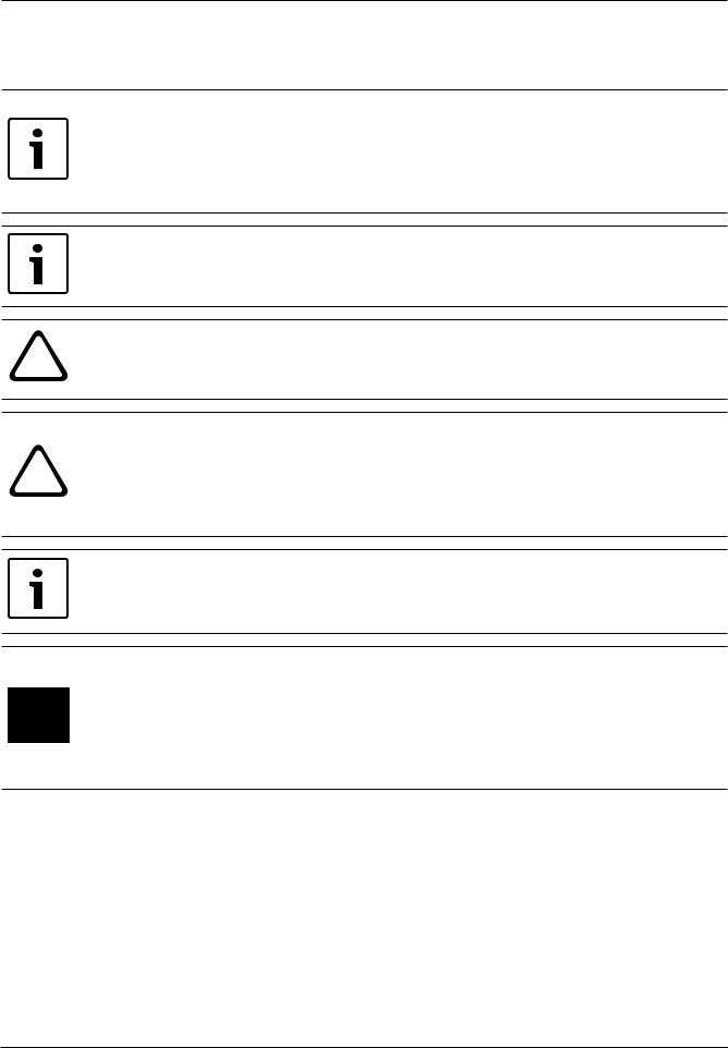
3.2.2Ethernet loop
For this configuration, the notes, settings, parameters and features specified in Topologies, page 7 apply.
FPA/FMR
FX
FPA/FMR |
FPA-5000 |
TX |
TX |
TX |
|
|
|
|
TX |
TX |
|
|
|
|
|
|
|
|||||
|
|
|
|
|
|
|
|
||
|
|
|
|
|
|
|
|
|
|
|
|
|
|
|
|
|
|
|
|
FX |
FX |
FX |
FX |
|
|
|
Figure 3.1: Ethernet loop
Key, see Key, page 10
2017.12 | 5.7 | F.01U.247.450 |
Networking Guide |
Bosch Sicherheitssysteme GmbH |
Modular Fire Panel |
Connecting FPA-5000 | en 13 |
|
|
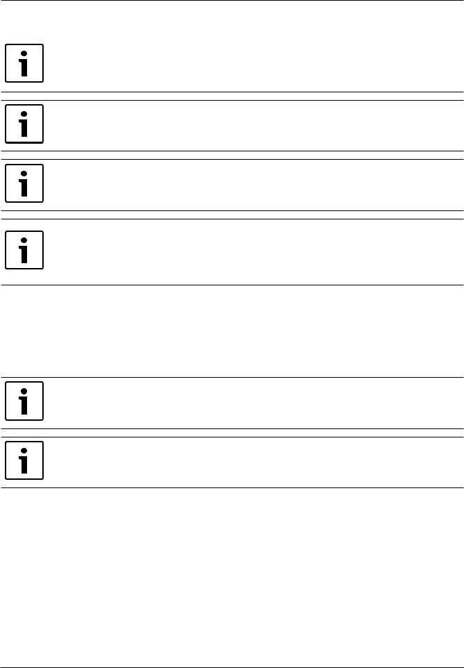
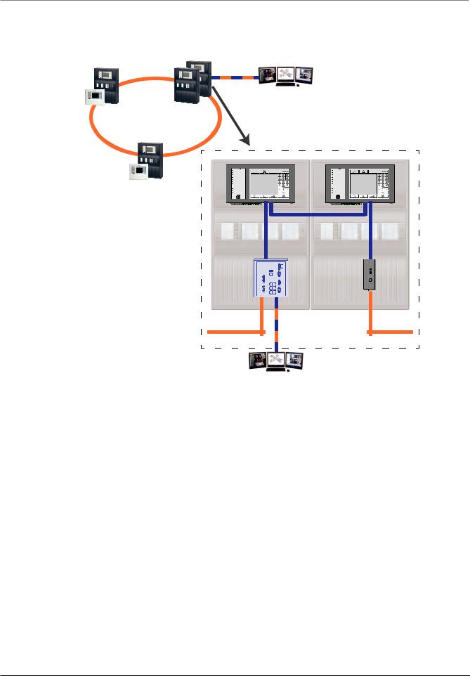
3.2.3Ethernet loop with OPC server
For this configuration, the notes, settings, parameters and features specified in Topologies, page 7 apply.
The information given here expands on Topologies, page 7.
Switch for connecting the OPC server must be programmed separately
Program the IP address and redundancy settings of the switch, see Settings on switch, page 38. As the switch is installed in the immediate vicinity (without intermediate space), the power supply does not have to be designed redundantly and the fault outputs are therefore not used.
Make sure that the RSTP settings in the panel controllers, RPS programming software and switch are identical.
OPC server must be programmed separately
Program the IP address, network nodes, network group and RSN, see OPC servers, page 59. The OPC server uses port 25000 as standard.
Make sure that the settings in the RPS programming software and OPC server are identical.
Parameters
–The OPC server may be connected via an Ethernet cable (copper) or fiber optic cable.
OPC-SERVER
FPA/FMR |
|
FX |
TX |
|
FPA/FMR |
FPA-5000 |
|
FX |
TX
FX |
OPC-SERVER
Figure 3.2: Ethernet loop with OPC server
Key, see Key, page 10
Bosch Sicherheitssysteme GmbH |
Networking Guide |
2017.12 | 5.7 | F.01U.247.450 |
14 en | Connecting FPA-5000 |
Modular Fire Panel |
|
|
3.2.4Ethernet loop with OPC server to redundant panel controller
FX
OPC-SERVER
FPA/FMR |
FPA-5000 |
|
|
|
||
|
|
|
|
|
|
|
|
|
|
|
|
|
|
|
|
|
|
|
|
|
|
|
|
|
|
|
|
FPA/FMR
TX |
TX |
FX |
FX |
OPC-SERVER
Figure 3.3: Ethernet loop with OPC server to redundant panel
Key, see Key, page 10
2017.12 | 5.7 | F.01U.247.450 |
Networking Guide |
Bosch Sicherheitssysteme GmbH |
Modular Fire Panel |
Connecting FPA-5000 | en 15 |
|
|
3.2.5Ethernet/CAN double loop
For this configuration, the notes, settings, parameters and features specified in Topologies, page 7 apply.
CAN
FPA/FMR
FPA/FMR
FPA-5000
CAN
TX
FX |
CAN
TX
FX |
|
TX |
TX |
TX |
CAN |
FX |
CAN |
FX |
Figure 3.4: Double loop of Ethernet and CAN
Key, see Key, page 10
Bosch Sicherheitssysteme GmbH |
Networking Guide |
2017.12 | 5.7 | F.01U.247.450 |

16 en | Connecting FPA-5000 |
Modular Fire Panel |
|
|
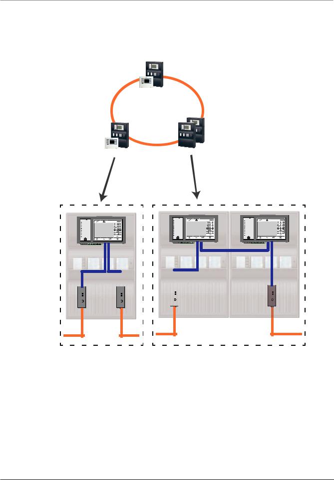
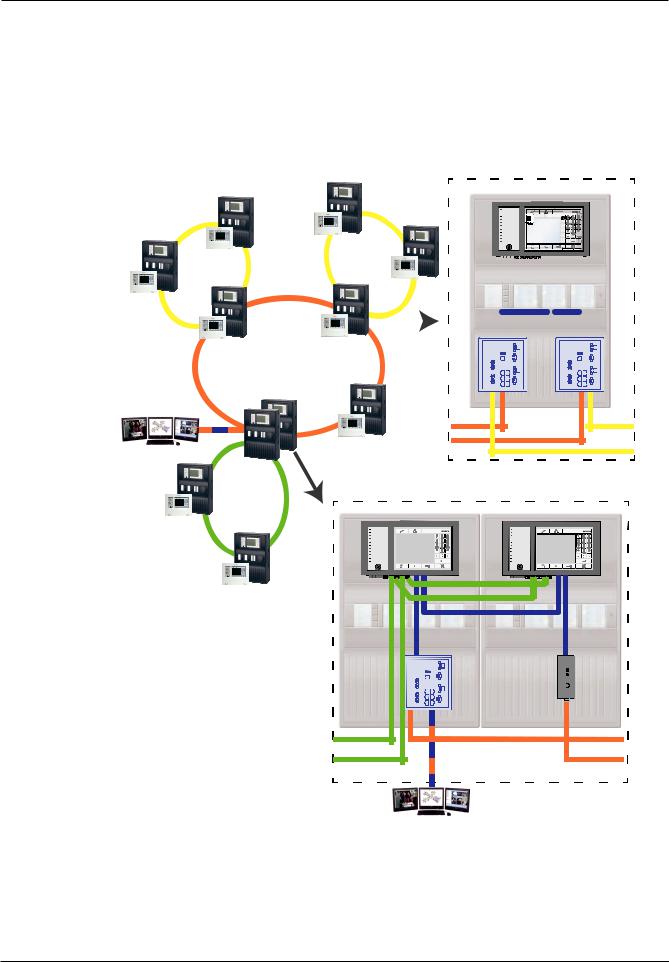
3.2.6Ethernet backbone with sub-loops (Ethernet/CAN)
For this configuration, the notes, settings, parameters and features specified in Topologies, page 7 apply.
The information given here expands on Topologies, page 7.
Notice!
This topology requires additional settings for all RSTP nodes in the backbone. More in-depth knowledge of networks is therefore required.
Please note that with this topology you are required to determine the network diameter, see Network diameter, page 20. Only RSTP devices are included in the network diameter, CANnetworked panels are disregarded.
Notice!
If the panel acts as an interface with a CAN sub-loop, this panel must then also be designed redundantly according to EN 54 2 if more than 512 detection points are connected in the subloop.
This restriction does not apply in an Ethernet sub-loop, as the switches to connect the 2 loops perform the redundancy.
Additional settings
You must operate the central loop as the backbone. This must be networked via the Ethernet.
Notice!
For all panels and switches in the backbone, set a higher RSTP priority than in the sub-loops. This ensures that the RSTP root bridge will always remain in the backbone, even in the event of a fault.
The switches to connect the loops are part of the backbone! Use a RSTP priority of 16384 in the backbone.
Notice!
The lower the set value, the higher the RSTP priority.
Settings for loops with more than 20 RSTP devices
Panel controllers connected via CAN are not regarded as RSTP switches when determining the network diameter.
Switches for connecting the OPC server and the sub-loops must be programmed separately
Program the IP address and redundancy settings of the switches, see Settings on switch, page 38. For this topology, the fault outputs of the switch only have to be used if you have designed the power supply for the switch redundantly or there is a switch-to-switch connection, see Switch with power supply and fault relay.
Make sure that the RSTP settings in the panel controllers, RPS programming software and switch are identical.
Notice!
Change the RSTP priority for the switches for connecting the loops, as they belong to the backbone.
2017.12 | 5.7 | F.01U.247.450 |
Networking Guide |
Bosch Sicherheitssysteme GmbH |
Modular Fire Panel |
Connecting FPA-5000 | en 17 |
|
|
OPC server must be programmed separately
Program the IP address, network nodes, network group and RSN, see OPC servers, page 59. The OPC server uses port 25000 as standard.
Make sure that the settings in the RPS programming software and OPC server are identical.
Parameters
–The OPC server may be connected via an Ethernet cable or fiber optic cable
FX |
|
FX |
|
|
|
|
|
|
|
|
|
|
|
|
|
|
|
FPA/FMR |
FPA/FMR |
|
|
|
|
|
|
|
|
|
|
|
|
|
|
||
|
|
|
|
|
|
|
|
|
|
|
|
|
|
||||
|
|
|
|
|
|
|
|
|
|
|
|
|
|
||||
|
|
|
|
|
|
|
|
|
|
|
|
|
|
|
|
|
|
|
|
|
|
|
|
|
|
|
|
|
|
|
|
|
|
|
|
|
|
|
|
|
|
|
|
|
|
|
|
|
|
|
|
|
|
FX |
|
FPA/FMR |
|
|
|
|
|
|
|
|
|
|
|
|
|
||
FPA/FMR |
|
|
|
|
|
|
|
|
|
|
|
|
|
|
|
|
|
|
|
|
|
|
TX |
|
|
|
|
|
|
|
TX |
|
|
||
|
|
|
|
|
|
|
|
|
|
|
|
|
|
||||
FPA/FMR |
FPA/FMR |
|
|
|
|
|
|
|
|
|
|
||||||
|
|
|
|
|
|
|
|
|
|
|
|
|
|||||
|
|
|
|
|
|
|
|
|
|
|
|
||||||
|
|
|
|
|
|
|
|
|
|
|
|
|
|
|
|
|
|
OPC-SERVER
FPA-5000
FX |
FX |
FPA/FMR |
FX |
FX
FPA/FMR
FPA/FMR |
|
|
TX |
TX |
TX |
CAN |
FX |
CAN |
FX |
OPC-SERVER
Figure 3.5: Ethernet backbone with sub-loops
Key, see Key, page 10
Bosch Sicherheitssysteme GmbH |
Networking Guide |
2017.12 | 5.7 | F.01U.247.450 |

18 en | Connecting FPA-5000 |
Modular Fire Panel |
|
|
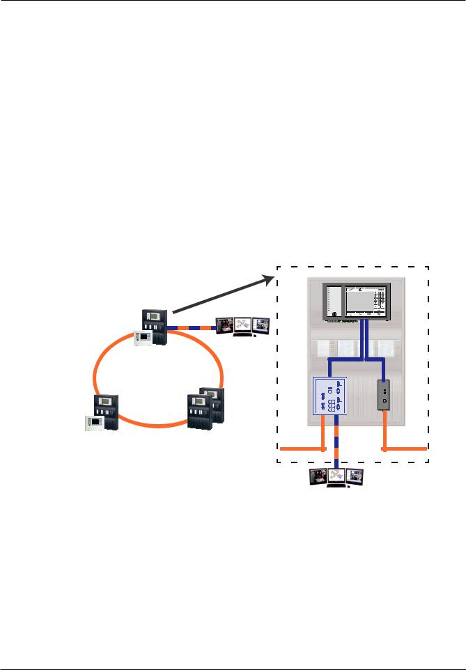
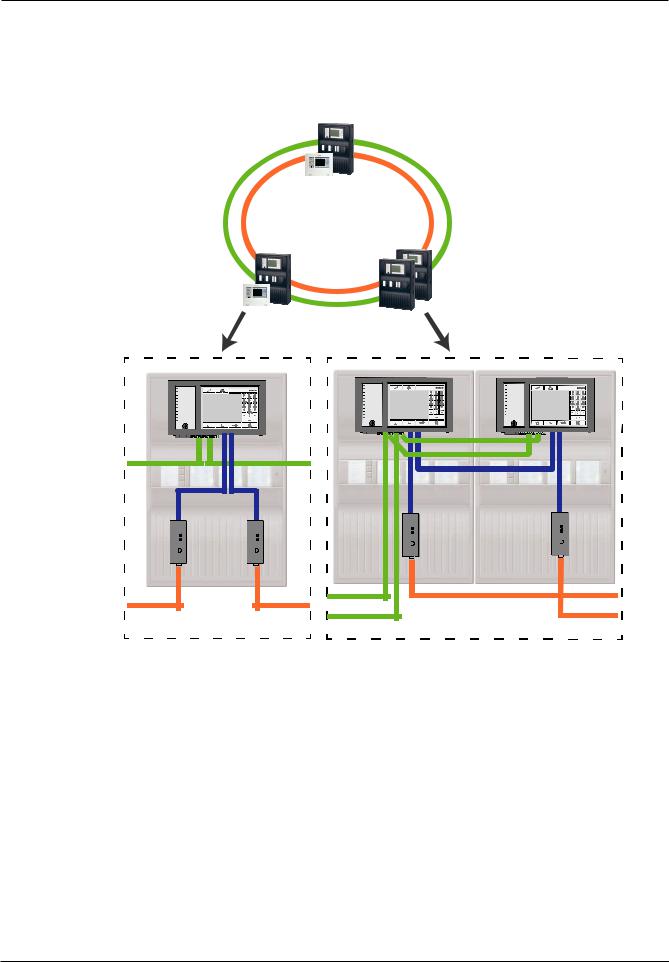
3.2.7Connecting Ethernet loops
For this configuration, the notes, settings, parameters and features specified in Topologies, page 7 apply.
The information given here expands on Topologies, page 7.
Notice!
This topology requires additional settings for all RSTP nodes in the backbone. More in-depth knowledge of networks is therefore required.
Additional settings
This topology is a special instance of the Ethernet backbone with sub-loops, see Ethernet backbone with sub-loops (Ethernet/CAN), page 16. You must operate one of the two loops as the backbone.
Notice!
For all panels and switches in the backbone, set a higher RSTP priority than in the sub-loops. This will ensure that the RSTP root bridge will always remain in the backbone, even in the event of a fault.
The switches to connect the two loops are part of the backbone! Use a RSTP priority of 16384 in the backbone.
Notice!
The lower the set value, the higher the RSTP priority.
Switches for connecting the OPC server and the second loop must be programmed separately
Program the IP address and redundancy settings of the switch, see Settings on switch, page 38. For this topology, the fault outputs of the switch only have to be used if you have designed the power supply for the switch redundantly, for connections see Switch with power supply and fault relay.
Make sure that the RSTP settings in the panel controllers, RPS programming software and switch are identical.
Change the RSTP priority for the switches for connecting the two loops, as they belong to the backbone.
OPC server must be programmed separately
Program the IP address, network nodes, network group and RSN, see OPC servers, page 59. The OPC server uses port 25000 as standard.
Make sure that the settings in the RPS programming software and OPC server are identical.
Parameters
– The OPC server may be connected via an Ethernet cable (copper) or fiber optic cable In these examples, loop a is the backbone. Loop b is the sub-loop.
2017.12 | 5.7 | F.01U.247.450 |
Networking Guide |
Bosch Sicherheitssysteme GmbH |

Modular Fire Panel |
Connecting FPA-5000 | en 19 |
|
|
FX
|
|
|
|
|
|
|
|
|
|
|
|
|
|
|
|
|
|
|
|
|
|
|
|
|
|
|
|
|
|
|
|
|
|
|
|
|
|
|
|
|
|
|
|
|
|
|
|
|
|
|
|
|
|
|
|
|
|
|
|
|
|
|
|
|
|
|
|
|
|
|
|
|
|
|
|
|
|
|
|
|
|
|
|
|
|
|
|
|
|
|
|
|
|
|
|
|
|
|
|
|
|
|
|
|
FPA/FMR |
A |
|
|
|
|
|
|
|
|
|
|
|
|
|
FPA/FMR
TX |
TX |
|
OPC-SERVER |
|
|
FPA/FMR |
|
|
|
B |
|
A |
FX B |
FX |
FX |
||
|
|
FX |
FX |
|
|
|
FPA-5000
FPA/FMR
OPC-SERVER
Figure 3.6: Connecting Ethernet loop via a non-redundant panel
FX FX
A B
FPA/FMR
FPA/FMR
FPA-5000
FPA/FMR
FPA/FMR
OPC-SERVER
TX |
TX |
OPC-SERVER
A |
FX |
|
|
|
|
FX |
|
|
|
|
|
|
|
|
|
|
|
|
|
|
|
FX |
B |
|
|
|
|
|
|
||
|
FX |
|
|
|
|
||
|
|
|
|
|
|
|
Figure 3.7: Connecting Ethernet loop via a redundant panel
Key, see Key, page 10
Bosch Sicherheitssysteme GmbH |
Networking Guide |
2017.12 | 5.7 | F.01U.247.450 |

20 en | Connecting FPA-5000 |
Modular Fire Panel |
|
|
3.3Ethernet network
In the network, the Ethernet network connections are monitored continuously. If a connection has been severed, then the interruption is detected. Repaired connections are also detected.
MAC addresses
Each panel controller has 3 MAC addresses.
–MAC address for the host
–MAC address for network connection 1 (Eth 1)
–MAC address for network connection 2 (Eth 2)
The network diagnosis of the panel always shows you the MAC address of the hosts connected via the network.
3.3.1Protocols
SNMP
SNMP is used to monitor and control network components. To this end, parameters of network nodes can be read out or modified. For this you require the appropriate network management software (e.g. Hirschmann HiVision).
Notice!
The network uses the following SNMP password: PUBLIC
LLDP
LLDP is a basic protocol standardized by the IEEE. It is used to share network information between neighboring devices. This information is
–provided as part of the SNMP data
–displayed via the panel controller as part of the network diagnostic data
RSTP
RSTP is a network protocol standardized by the IEEE. RSTP ensures that there are no loops in networks. Redundant paths are detected in the network, deactivated and activated when necessary (failure of a connection).
The protocol is used for exactly this purpose in the network.
A change to the bus topology following the failure of a connection is automatically canceled once it has been repaired.
3.3.2Network diameter
The network diameter of FPA-RSTP Ethernet networks must not be greater than 32.
Definition
The diameter of a network corresponds to the number of RSTP switches on the longest possible section without loops between any 2 end points in the network.
The following must be taken into account in relation to a FPA-RSTP Ethernet network:
–Each MPC contains an end point and an internal RSTP switch.
–A combination of MPC and redundant MPC counts as just one RSTP switch.
–Media converters are not regarded as RSTP switches.
–CAN connections may not be included in the longest possible section.
–OPC servers are not taken into account with respect to the diameter.
Key |
|
CPU |
Central processor in the panel controller or in the remote |
|
|
|
keypad. |
2017.12 | 5.7 | F.01U.247.450 |
Networking Guide |
Bosch Sicherheitssysteme GmbH |
Modular Fire Panel |
Connecting FPA-5000 | en 21 |
|
|
S |
Internal RSTP switch in the panel controller or in the remote |
|
keypad. |
||
|
|
Panel controller or remote keypad with central processor and |
CPU |
internal RSTP switch. |
|
S |
Redundant panel controller with central processor and internal
RSTP switch.
Panel controller/remote keypad
Starting point/end point for determining the diameter in the examples.
Ethernet Switch (in general Ethernet Switch MM) as external
RSTP switch
2 connected panels form the smallest possible loop. The diameter of this network is equal to 2, as the internal switches are located between the end points.
MPC |
|
MPC |
|
||||||||||||||
|
|
|
|
|
|
|
|
|
|
|
|
|
|
|
|
|
|
CPU |
|
|
|
|
|
|
|
|
CPU |
|
|
|
|
|
|
|
Ø = 2 = # |
|
|
|
|
S |
|
|
|
|
|
S |
|||||||
|
|
|
|
|
|
|
|
|
|||||||||
|
|
|
|
|
|
|
|
|
|
||||||||
|
|
|
|
|
|
|
|
|
|
|
|
|
|
|
|
|
|
|
|
|
|
|
|
|
|
|
|
|
|
|
|
|
|
|
|
|
|
|
|
|
|
|
|
|
|
|
|
|
|
|
|
|
|
Figure 3.8: Network diameter of a loop with 2 panels
In a panel loop without external switches, the diameter of the network corresponds to the number of installed panels.
|
MPC |
MPC |
|
|
|
|
|
|
CPU |
CPU |
|
|
|
|
|
|
2 |
1 |
MPC |
|
|
||
|
|
|
|
MPC |
|
|
CPU |
|
|
|
6 |
CPU |
|
|
Ø = 6 = # |
3 |
|
|
|
|
|
MPC |
|
|
MPC |
|
|
|
|
CPU |
|
|
CPU |
|
5 |
|
|
|
|
|
4 |
|
|
Figure 3.9: Network diameter of a loop with 6 panels
If a backbone and sub-loops are connected to each other via RSTP switches not integrated into the panel controller, then the RSTP switches must also be taken into account.
Bosch Sicherheitssysteme GmbH |
Networking Guide |
2017.12 | 5.7 | F.01U.247.450 |
Loading...