


FMM-325A
FMM-325A, FMM-325A-D Installation Guide Analog Addressable Manual Pull Stations
1.0 Description
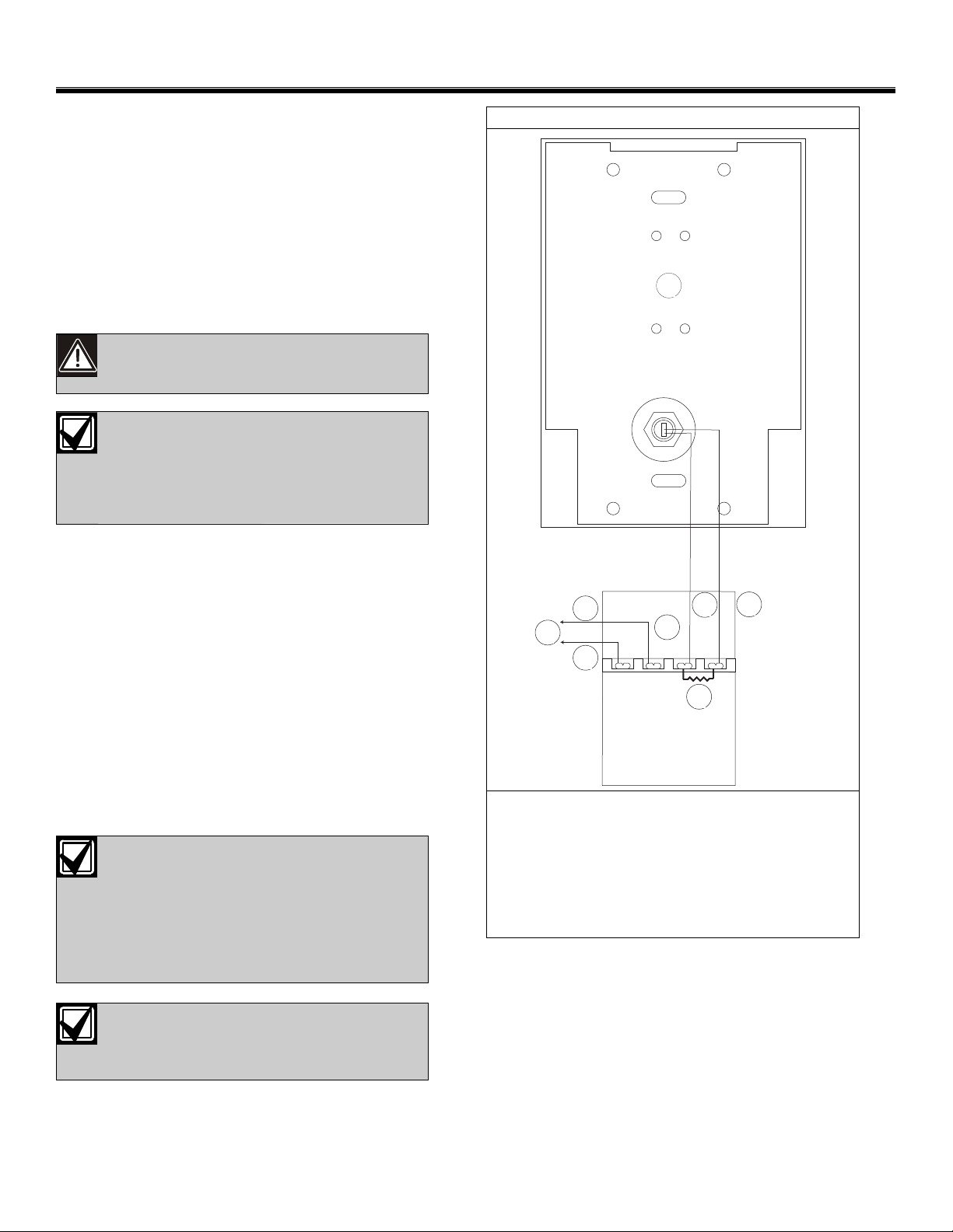
Figure 1: FACP Wiring
These instructions cover the installation of the FMM-325A (Single
Action) and FMM-325A-D (Dual Action) Analog Addressable
Manual Pull Station kits in an analog system controlled by Bosch
FPA-1000 Analog Addressable Fire Alarm Control Panels
(FACPs). The kits contain an FLM-325-IM Contact Module with
either an FMM-100-S or FMM-100-D Manual Pull Station.
Install, test and maintain the pull stations according to these
instructions, NFPA 72, Local Codes and the Authority Having
Jurisdiction (AHJ). Failure to follow these instructions may result
in failure of the device to operate properly. Bosch is not
1
responsible for improperly installed, tested or maintained devices.
These instructions contain procedures to
follow in order to avoid personal injury and
damage to equipment.
NFPA 72 requires a complete system wide
functional test be performed following any
modifications, repair, upgrades, or
adjustments made to the system's
components, hardware, wiring,
programming, and software/firmware.
The FMM-100-S and FMM-100-D Manual Pull Stations are UL
Listed manual alarm-initiating devices. They communicate with
the FACP polling circuit through an FLM-325-IM Analog
Addressable Point Contact Module. The die cast housing flush
mounts to a single gang switch box, having a minimum depth of
2-1/8 in. (5.4 cm) or surface mounts using an FMM-100BB-R
Surface-mount Back Box. The alarm lever cam actuator latches
when pulled and the reset is keyed. A scored acrylic break rod
(P/N: FMM-100GR) is optional.
2.0 Installation
4
6
SC-
S+
5
IN +
FLM-325-IM
2
3
IN -
7
2.1 Wiring the Alarm Box to the FACP
For details on address programming and wiring, refer to the
FLM-325-IM Installation Instructions (DWG# HA-06-269, Part#
1700-11730) and the D5070 Programmer Operating Instructions
(DWG# HA-06-242, Part#1700-11460).
1. Set the device address on the FLM-325-IM.
Set the FMM-325A/FMM-325A-D address
on the FLM-325-IM before wiring the
module and installing it in the back box.
Once the pull station and point contact
module are installed in the back box,
setting or changing the address involves
removing the device and opening the
module case.
2. Connect the FLM-325-IM to the FACP as shown in Figure 1.
Since the FLM-325-IM will be installed
inside the back box, run the wires from
the module to the FACP through an
appropriate knockout on the back box.
1 - Back of FMM-100-S/FMM-100-D
2 - FLM-325-IM
3 - Wiring from pull station alarm contacts
4 - Data/power SLC common out (SC-)
5 - Data/power SLC positive out (S+)
6 - To next device or FACP
7 - 10 k
2.2 Installing the Pull Station in a Back Box
When the device address has been set and the wire connections
from the FLM-325-IM to the FACP have been made, proceed with
installing the manual pull station in the back box.
2.2.1 Flush Mounting in a Single-gang Back Bo x
1.
2. Use the screw provided with the back box to hold the back
Ω
EOL resistor (Hochiki P/N: 0400-01046)
Position the point contact module so that the hole in its
mounting plate aligns with the upper attachment slot in the
back plate of the manual pull station.
plate of the manual pull station and the point contact module
to the upper mounting hole of the back box.
 Loading...