


FPP-RNAC-8A-4C
Operation and Installation Guide
EN Remote NAC Power
Supply

FPP-RNAC-8A-4C | Operation and Installation Guide |
Notice to Users, Installers, Authorities Having Jurisdiction, and other involved parties:
This product incorporates fieldprogrammable software. In order for the product to comply with the requirements in the Standard for Control Units and Accessories for Fire Alarm Systems, UL864, certain programming features or options must be limited to specific values or not used at all as indicated below.
Program Feature or Option |
Permitted in UL864? |
|
Possible Settings |
|
Settings Permitted in |
|
(Y/N) |
|
|
|
UL864 |
Ground Fault Detection |
N |
Jumper in place (enabled) |
|
Jumper in place (enabled), |
|
disable |
|
|
Jumper removed (disabled) |
|
only |
|
|
|
|
|
|
|
|
|
|
|
|
2 |
Bosch Security Systems, Inc. | 8/09 | F01U025431-02 |

FPP-RNAC-8A-4C | Operation and Installation Guide |
Contents |
|
|
1.0 |
Overview ........................................................... |
4 |
1.1 |
Module Control................................................... |
4 |
1.1.1 |
Option Bus Control ........................................... |
4 |
1.1.2 |
Conventional NAC Input Control ................... |
4 |
1.2 |
Output Bell Operation ....................................... |
4 |
1.3 |
Power Management.......................................... |
4 |
1.4 |
Low AC Line Detection ..................................... |
4 |
1.5 |
Ground Fault Monitoring................................... |
4 |
1.6 |
Circuit Supervision ............................................ |
4 |
1.7 |
Overvoltage Supervision .................................. |
4 |
1.8 |
Expander Supervision....................................... |
5 |
1.9 |
Auxiliary Power Supply..................................... |
5 |
2.0 |
Installing the FPP-RNAC-8A-4C................... |
5 |
2.1 |
FPP-RNAC-8A-4C Board Installation............. |
6 |
2.2 |
Enclosure Installation........................................ |
6 |
3.0 |
Wiring the FPP-RNAC-8A-4C........................ |
8 |
3.1 |
AC Power Connections .................................... |
8 |
3.2 |
Battery Connections (24 VDC Only)............. |
10 |
3.3 |
Option Bus Connections................................. |
14 |
3.4 |
NAC Input Connections.................................. |
14 |
3.5 |
Trouble Relay Connections ........................... |
15 |
3.6 |
Auxiliary Output Connections ........................ |
15 |
3.7 |
NAC Output Connections............................... |
15 |
3.7.1 |
NAC Circuits .................................................... |
15 |
3.7.2 |
Auxiliary Circuits ............................................. |
16 |
3.7.3 |
EOL Reference Programming ........................ |
16 |
4.0 |
DIP Switch and Option Bus Settings........ |
17 |
4.1 |
Switch S1........................................................... |
17 |
4.2 |
Switch S2........................................................... |
18 |
4.3Conventional (Polarity Reversal) Inputs 1
|
and 2.................................................................. |
19 |
4.4 |
Option Bus Address ........................................ |
20 |
4.5 |
NAC Input Variable ......................................... |
20 |
4.6 |
AC Fail Time Delay ......................................... |
20 |
5.0FPP-RNAC-8A-4C Local Status Display ..21
6.0 |
Specifications................................................. |
23 |
Figures |
|
|
Figure 1: |
FPP-RNAC-8A-4C Remote NAC |
|
|
Power Supply Board.................................. |
5 |
Figure 2: |
FPP-RNAC-8A-4C Enclosure and |
|
|
Board Installation ....................................... |
7 |
Figure 3: |
AC Power Connections............................. |
9 |
Figure 4: |
Install Ferrite Core ..................................... |
9 |
Figure 5: |
Battery Connections Inside |
|
|
FPP-RNAC-8A-4C Enclosure ................ |
10 |
Figure 6: |
Battery Connections Using an External |
|
|
Battery Case............................................. |
11 |
Figure 7: |
Wiring the Option Bus ............................. |
14 |
Figure 8: |
Wiring the NAC Inputs............................. |
14 |
Figure 9: |
Wiring the Trouble Relay ........................ |
15 |
Figure 10: |
Wiring the Auxiliary Outputs................... |
15 |
Figure 11: |
Wiring the NAC outputs and EOL.......... |
16 |
Figure 12: |
Auxiliary Power Configuration................ |
16 |
Figure 13: |
FPP-RNAC-8A-4C LEDs ........................ |
22 |
Tables |
|
|
Table 1: Wire Gauge Calculations................................ |
8 |
|
Table 2: Wire Gauge Table (based on solid wire) ...... |
8 |
|
Table 3: Standby Time Calculation............................. |
12 |
|
Table 4: Calculating the Required Battery Size........ |
12 |
|
Table 5: Standby Load Battery Capacity (in ampere- |
||
|
hours [Ah]) ................................................ |
13 |
Table 6: Alarm Load Battery Capacity (in ampere- |
|
|
|
hours [Ah])) ............................................... |
13 |
Table 7: DIP Switch S1 Settings ................................. |
17 |
|
Table 8: DIP Switch S2 Settings ................................. |
18 |
|
Table 9: Using Conventional Inputs 1 and 2 to |
|
|
|
Operate Outputs (Switch 2, |
|
|
Position 0) ................................................. |
19 |
Table 10: Local Status Display LED Functions......... |
21 |
|
Table 11: Specifications ............................................... |
23 |
|
Bosch Security Systems, Inc. | 8/09 | F01U025431-02 |
3 |

FPP-RNAC-8A-4C | Operation and Installation Guide | |
1.0 |
Overview |
|
|
|
1.0 Overview
The FPP-RNAC-8A-4C is a Remote Notification Appliance Circuit (NAC) Power Supply designed to add four additional NACs (NFPA 72 Class B, Style Y or Class A, Style Z) to a Fire Alarm Control Panel (FACP).
The FPP-RNAC-8A-4C is supervised by the control panel. It consists of the controller board, backup batteries, and enclosure.
The FPP-RNAC-8A-4C is also compatible with any UL Listed control unit utilizing:
•reverse polarity supervised notification appliance circuit (NAC) outputs, and
•12 or 24 VDC regulated outputs.
Each output can be configured individually as a NAC or constant 24 V auxiliary power supply.
1.1Module Control
1.1.1Option Bus Control
The FPP-RNAC-8A-4C can connect to the Option Bus of the FPA-1000 or FPD-7024 Fire Alarm Control/Communicator.
Refer to Section 3.3 Option Bus Connections on page 14 for information on wiring.
1.1.2Conventional NAC Input Control
For conventional panels, the FPP-RNAC-8A-4C connects using the FACP’s NAC outputs that conform to NFPA 72 Class A or B. Please refer to the control panel’s NAC compatibility information.
1.2Output Bell Operation
The FPP-RNAC-8A-4C can generate three pulsed bell patterns on command in addition to steady activation of the output:
•Pulsed: 60 PPM (0.5 sec On, 0.5 sec Off)
•NFPA Temporal: In compliance with ANSI standard S3.41: 0.5 sec On, 0.5 sec Off, 0.5 sec On, 0.5 sec Off, 0.5 sec On, 1.5 sec Off, and so on.
•California March: 120 ppm (0.25 sec on, 0.25 sec off).
You can also implement SYNC protocols:
•Wheelock SYNC Protocol
•Gentex SYNC Protocol
•System Sensor SYNC Protocol
All outputs are synchronized if the conventional inputs are activating the FPP-RNAC-8A-4C.
For option bus synchronization information, refer to the control panel documentation.
1.3Power Management
The controlling section of the board has uninterruptible power. If AC line voltage is lost, the power supply switches to battery backup.
1.4Low AC Line Detection
Sensing circuitry detects a line input voltage below 85 VAC, then switches from the primary AC Line voltage to battery backup.
1.5Ground Fault Monitoring
The option bus and polarity reversal inputs are electrically isolated from the local power supply and indicating circuits. The FPP-RNAC-8A-4C supervises itself for grounded field connections and indicates a fault condition if one is found. This feature can be disabled by opening Switch S4.
For UL864 installations, do not disable ground fault monitoring.
1.6Circuit Supervision
Each NAC is supervised for short-circuit and open conditions using an end-of-line (EOL) resistor on the loop. Devices on these loops must have a blocking diode on their input so that the EOL supervision resistor can be read when the polarity of the output is reversed in the standby state. The devices activate when the polarity is switched back to normal in an alarm state. The EOL is programmable from 1 kΩ to 20 kΩ. This allows existing systems to be retrofitted.
1.7Overvoltage Supervision
The power supply output is monitored for overvoltage conditions. If an overvoltage condition exists (30 V or more on battery leads without the battery connected), the trouble relay and EOL relays open. In addition, the trouble LED lights. On the option bus, AC fail, ground fault, and NAC troubles are initiated.
4 |
Bosch Security Systems, Inc. | 8/09 | F01U025431-02 |
FPP-RNAC-8A-4C | Operation and Installation Guide |
1.8Expander Supervision
A watchdog supervises the operation of the FPP-RNAC-8A-4C processor and attempts to restart it if it fails. If the processor does not restart, or the power fails entirely, the installer-supplied EOL device disconnects from the input to report the trouble condition. If power is available, the System Trouble LED lights if the system encounters an error.
1.9Auxiliary Power Supply
The FPP-RNAC-8A-4C can be wired to supply unsupervised constant auxiliary power through its NAC outputs. Refer to Section 3.7.2 Auxiliary Circuits on page 16 for additional information.
2.0 Installing the FPP-RNAC-8A-4C
The FPP-RNAC-8A-4C board and the enclosure are shipped together. The board, however, needs to be mounted into the enclosure. Hardware for mounting the board in the enclosure is supplied in the hardware pack.
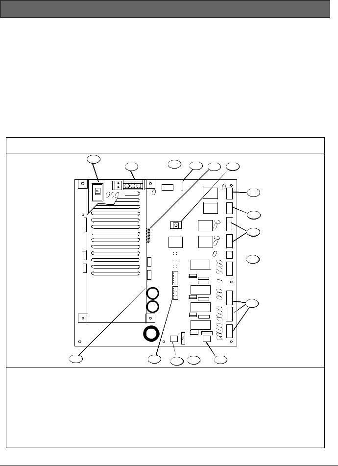
Figure 1: FPP-RNAC-8A-4C Remote NAC Power Supply Board
1 |
|
3 |
4 |
|
|
6 |
|
2 |
|
|
5 |
|
|||
OPTION BUS |
|
|
|
|
|
||
R |
Y |
G B |
GROUND FAULT |
BOSCH |
4998149856 |
|
|
|
|
|
OPEN = DISABLE |
|
|
||
|
|
|
CLOSE = ENABLE |
|
|
AC |
|
|
|
|
|
|
|
T |
7 |
|
|
|
|
|
|
R |
|
|
|
|
|
|
|
O |
|
|
|
|
|
|
|
U |
|
|
|
|
|
|
|
B |
|
|
|
|
|
|
|
L |
|
|
|
|
|
|
|
E |
|
|
|
|
|
|
|
T |
|
|
|
|
|
|
|
R |
|
|
|
|
|
|
|
O |
|
|
|
|
|
|
|
U |
|
|
|
|
|
|
|
B |
|
|
|
|
|
|
|
L |
8 |
|
|
|
|
|
|
E |
|
|
|
TROUBLE |
|
|
I |
||
|
|
RESET |
|
|
|
||
FLASH |
|
|
|
|
|
N |
|
|
|
|
|
|
P |
|
|
PROGRAMMING |
|
|
|
|
|
U |
|
PORT |
|
|
|
|
|
T |
|
|
|
|
|
|
|
2 |
9 |
|
|
|
|
|
|
I |
|
|
|
|
|
|
|
N |
|
|
|
|
|
|
|
P |
|
|
|
|
|
|
|
U |
|
|
|
|
|
|
|
T |
|
|
|
|
|
|
|
1 |
|
|
|
|
INPUT ACTIVE |
|
|
|
|
|
|
|
AC OK |
|
|
EOL |
|
|
|
|
SYSTEM TROUBLE |
|
|
REF |
10 |
|
|
|
GROUND FAULT |
|
|
|
|
|
|
|
TROUBLE 4 |
|
|
|
|
|
|
|
TROUBLE 3 |
|
|
O |
|
|
|
|
TROUBLE 2 |
|
|
|
|
|
|
|
TROUBLE 1 |
|
|
U |
|
|
|
|
|
|
T |
|
|
|
|
|
|
|
|
P |
|
|
|
|
|
|
|
U |
|
|
|
|
|
|
|
T |
|
|
|
|
|
|
|
4 |
|
|
|
|
|
|
|
O |
|
|
|
|
|
|
|
U |
|
|
|
|
|
|
|
T |
|
|
|
|
|
|
|
P |
|
|
|
|
|
|
|
U |
|
|
|
|
|
|
|
T |
11 |
|
|
|
|
|
|
3 |
|
|
|
|
|
|
|
|
|
|
|
|
|
|
|
O |
|
|
|
|
|
|
|
U |
|
|
|
|
|
|
|
T |
|
|
|
|
|
|
|
P |
|
|
|
|
|
|
|
U |
|
|
|
|
|
|
|
T |
|
|
|
|
|
|
|
2 |
|
|
|
|
|
|
|
O |
|
|
|
|
|
|
|
U |
|
|
|
|
|
|
|
T |
|
|
|
REPLACE WITH 15A |
|
|
P |
|
|
|
|
BLADE TYPE FUSE |
|
|
U |
|
|
|
|
|
|
|
|
T |
|
|
|
|
|
|
|
1 |
|
|
|
- BATTERY + |
- AUX POWER + |
|
|
||
|
16 |
15 |
14 |
13 |
12 |
1 |
AC Input Select Switch 120/240 VAC |
|
9 |
NAC inputs |
|
2 |
AC Power Input 120/240 VAC |
|
10 |
EOL reference resistor (1kΩ to 20kΩ) |
|
3 |
Option bus |
|
11 |
NAC outputs |
|
4 |
Ground fault switch |
|
12 |
Auxiliary 24V filtered and regulated output |
|
5 |
Flash programming port |
|
|
power |
|
6 |
TROUBLE RESET button |
|
13 |
Replaceable 15A fuse |
|
7 |
AC trouble relay output |
|
14 |
Battery input |
|
8 |
Trouble relay output |
|
15 |
Configuration DIP switches |
|
|
|
|
16 |
Status LEDs |
|
Bosch Security Systems, Inc. | 8/09 | F01U025431-02 |
5 |

FPP-RNAC-8A-4C | Operation and Installation Guide | 2.0 Installing the FPP-RNAC-8A-4C
2.1FPP-RNAC-8A-4C Board Installation
The FPP-RNAC-8A-4C board is staticsensitive. Touch ground before handling the board. Doing so discharges any static electricity in your body.
1.Connect the ground wire.
2.Insert the two support posts into the control retainer holes as shown in Figure 2 on page 7.
3.Slide the top of the board into the retainer tabs (the slots under the top of the frame). When it is in the retainner tabs, the board rests on the two support posts.
4.To secure the bottom of the board, screw the two bottom corners through the support posts and through to the enclosure.
2.2Enclosure Installation
1.Use the enclosure as a template and mark the top mounting holes on the mounting surface. Ensure that enough clearance exists to open the door for maintenance.
2.Pre-start the mounting screws for the two holes. Slide the enclosure onto the mounting screws so that the screws move up into the thinner section of the holes. Tighten the screws.
3.Screw the remaining two screws into the bottom mounting holes.
4.Knock out the desired wire entrances on the enclosure.
Refer to Figure 2 on page 7 for details.
6 |
Bosch Security Systems, Inc. | 8/09 | F01U025431-02 |

FPP-RNAC-8A-4C | Operation and Installation Guide | 2.0 Installing the FPP-RNAC-8A-4C
Figure 2: FPP-RNAC-8A-4C Enclosure and Board Installation
|
1 |
|
|
|
|
|
|
|
4 |
2 |
|
|
|
|
|
5 |
3 |
|
|
|
|
1 |
5 |
|
|
|
|
|
|
||
|
OPTION BUS |
|
|
|
6 |
||
|
OPEN = DISABLE |
BOSCH |
4998149856 |
|
|||
|
R |
Y |
G B |
GROUND FAULT |
|
|
|
|
|
|
|
CLOSE = ENABLE |
|
AC |
|
|
|
|
|
|
|
T |
|
|
|
|
|
|
|
R |
|
|
|
|
|
|
|
O |
|
|
|
|
|
|
|
U |
|
|
|
|
|
|
|
B |
|
|
|
|
|
|
|
L |
|
|
|
|
|
|
|
E |
|
|
|
|
|
|
|
T |
|
|
|
|
|
|
|
R |
|
|
|
|
|
|
|
O |
|
6 |
|
|
|
|
|
U |
|
|
|
|
|
|
B |
|
|
|
|
|
|
|
|
L |
|
|
|
|
|
|
|
E |
|
|
|
|
TROUBLE |
|
I |
|
|
|
|
|
|
RESET |
|
|
|
|
FLASH |
|
|
|
|
N |
|
|
|
|
|
|
P |
|
|
|
PROGRAMMING |
|
|
|
|
U |
|
|
PORT |
|
|
|
|
T |
|
|
|
|
|
|
|
2 |
|
|
|
|
|
|
|
I |
|
|
|
|
|
|
|
N |
|
|
|
|
|
|
|
P |
|
|
|
|
|
|
|
U |
|
|
|
|
|
|
|
T |
|
|
|
|
|
|
|
1 |
|
|
|
|
|
INPUT ACTIVE |
|
|
|
|
|
|
|
AC OK |
|
EOL |
|
|
|
|
|
SYSTEM TROUBLE |
|
REF |
|
|
|
|
|
GROUND FAULT |
|
|
|
|
|
|
|
TROUBLE 4 |
|
|
|
|
|
|
|
TROUBLE 3 |
|
O |
|
|
|
|
|
TROUBLE 2 |
|
|
|
|
|
|
|
TROUBLE 1 |
|
U |
|
|
|
|
|
|
T |
|
|
|
|
|
|
|
|
P |
|
|
|
|
|
|
|
U |
|
|
|
|
|
|
|
T |
|
|
|
|
|
|
|
4 |
|
|
|
|
|
|
|
O |
|
|
|
|
|
|
|
U |
|
|
|
|
|
|
|
T |
|
|
|
|
|
|
|
P |
|
|
|
|
|
|
|
U |
|
|
|
|
|
|
|
T |
|
|
|
|
|
|
|
3 |
|
|
|
|
|
|
|
O |
|
|
|
|
|
|
|
U |
|
|
|
|
|
|
|
T |
|
|
|
|
|
|
|
P |
|
|
|
|
|
|
|
U |
|
|
|
|
|
|
|
T |
|
|
|
|
|
|
|
2 |
|
|
|
|
|
|
|
O |
|
|
|
|
|
|
|
U |
|
|
|
|
|
|
|
T |
|
|
|
|
REPLACE WITH 15A |
|
P |
|
|
|
|
|
BLADE TYPE FUSE |
|
U |
|
|
|
|
|
|
|
|
T |
|
|
|
|
|
|
|
1 |
|
|
|
|
- BATTERY + |
- AUX POWER + |
|
|
|
|
|
5 |
|
5 |
|
|
|
7 |
|
|
|
|
|
|
|
|
|
|
|
|
|
|
|
|
1 |
FPP-RNAC-8A-4C Printed circuit board |
5 |
Mounting screw holes |
|
|
2 |
Retainer hole in enclosure |
6 |
Wire entrance knockouts |
|
|
3 |
Support post |
7 |
Enclosure |
|
|
4 |
Mounting Screw |
|
|
|
|
|
|
|
||
|
Bosch Security Systems, Inc. | 8/09 | F01U025431-02 |
|
7 |
||
FPP-RNAC-8A-4C | Operation and Installation Guide | 3.0 Wiring the FPP-RNAC-8A-4C
3.0 Wiring the FPP-RNAC-8A-4C
All terminals are fully protected against electrostatic discharge (ESD) and transients.
Use wire gauge based on Table 1 and Table 2. The terminals can accommodate up to 12 AWG (2.0 mm) wire.
Table 1: Wire Gauge Calculations
|
|
|
Line No. |
Description |
Calculation |
|
|
|
1 |
Guaranteed minimum NAC voltage at full load. |
|
2 |
Minimum operating voltages (largest value of appliance on |
|
circuit) |
|
|
|
|
|
3 |
Maximum wiring voltage drop |
Subtract line 2 from line 1. |
4 |
Total load for a given NAC |
|
5 |
Maximum allowable line resistance |
Divide line 3 by line 4. |
6 |
Total wiring run length (feet) |
|
7 |
Total wire needed |
Multiply line 6 by line 2. |
8 |
Maximum wire resistance per foot |
Divide line 5 by line 7. |
9 |
Choose a wire size with a resistance per foot less than Line 7. |
|
|
|
|
Value
27.4 V
Table 2: Wire Gauge Table (based on solid wire)
|
|
AWG B&S Gauge |
Ohms per Foot |
|
|
12 (2.0 mm) |
0.00162 |
14 (1.6 mm) |
0.00258 |
|
|
16 (1.3 mm) |
0.00409 |
18 (1.0 mm) |
0.00651 |
|
|
NFPA 72 requires the use of 18 AWG (1.0 mm) or larger diameter wire in fire applications.
3.1AC Power Connections
Disconnect all power (AC and battery) before servicing the FPP-RNAC-8A-4C. Wait 60 sec before handling any connections.
AC Power runs to the L (Hot VAC), G (Ground), and N (Neutral) terminals.
120 VAC or 240 VAC with 8 A capacities should feed the local power supply. The output voltage is a filtered 27.6 VDC (500 mV ripple maximum) under all conditions.
A trouble condition is registered, but not indicated, if AC power fails. A programmable time delay (refer to
Section 4.6 AC Fail Time Delay on page 20) allows the indication of AC Failure to be delayed by 0, 6, 12, or 24 hrs. The default is 0 hrs.
Refer to Figure 3 on page 9 for wiring details.
Remember to select the appropriate voltage range for the AC input before applying any power to the product.
8 |
Bosch Security Systems, Inc. | 8/09 | F01U025431-02 |
 Loading...