


 Loading...
Fire Alarm Systems | FLM I 420 S Short Circuit Isolator
FLM I 420 S Short Circuit Isolator
Rotary switch for automatic and manual address setting
Preservation of LSN loop functions in the event of a short-circuit by two integrated isolators
Power supply via LSN
Three free screw terminals
The Short Circuit Isolator isolates alarm zones in which a short circuit has occurred. This means the functionality of the remainder of the network remains preserved.
Functions
Features of improved LSN
The interface modules in the 420 series offer all the features of improved LSN technology:
System Overview
CL 0 |
1 |
9 |
0 |
1 |
9 0 |
1 |
|
2 |
8 |
|
2 |
8 |
2 |
|
|
76 |
5 |
4 3 |
76 5 |
4 3 |
|
LSN |
|
|
|
|
|
b1+ |
a- |
b2+ |
N/A |
N/A |
N/A |
|
Description |
Connector |
b1+ / a- / b2+ |
LSN |
N/A (3 x) |
free terminals, e.g. for looping through ext. auxiliary volt- |
|
age and for shielding |
•Flexible network structures including T tapping without additional elements
•Up to 254 LSN-improved elements per loop or stub line
•Unshielded cable can be used
Address switch (rotary switch)
The address of the Short Circuit Isolator is set using the rotary switches.
The following settings are possible:
0 0 0 |
Loop/stub in LSN mode improved version with automatic |
|
addressing (T-tap system not possible) |
0 0 1 - 254 Loop/stub/T-tap system in LSN mode improved version
|
with manual addressing |
CL 0 0 |
Loop/stub in classic LSN mode |
Configuration
The Short Circuit Isolator isolates alarm zones in which a short circuit has occurred. The following illustrations show typical configurations of the isolator module.
www.boschsecurity.com
2 | FLM I 420 S Short Circuit Isolator |
|
|
|
|
|
||||
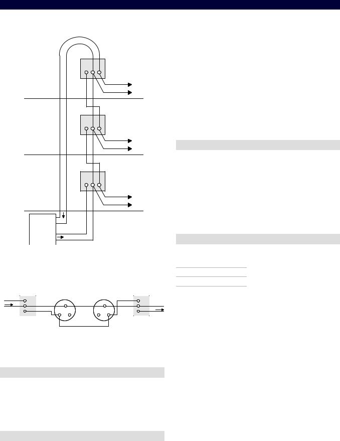
Wiring example: Isolation of separate floors |
|
• |
The surface-mounted housing has two cable ducts on |
||||||
|
|
|
|
|
|
|
opposite sides: |
|
|
|
|
|
|
|
|
|
- |
2 x 2 pre-punched for diameter up to 21 mm/to |
|
|
|
|
|
|
|
|
- |
34 mm (for conduits) |
|
|
|
|
|
FLM-I 420-S |
|
|
2 x 4 rubber bushes for inserting cables with |
||
|
|
b1+ |
a- |
b2+ |
|
• |
|
diameters of up to 8 mm. |
|
|
|
|
In addition, there are cable ducts on the base of the |
||||||
|
|
|
|
|
|
||||
|
|
|
|
|
|
|
surface-mounted housing: |
||
|
|
|
|
|
III |
|
- |
1 x pre-punched cable ducts for diameter up to |
|
|
|
|
|
|
|
|
- |
21 mm (for conduits) |
|
|
|
|
|
|
|
|
2 x 4 rubber bushes for inserting cables with |
||
|
|
|
|
|
|
• |
|
diameters of up to 8 mm. |
|
|
|
|
|
FLM-I 420-S |
|
Connectable to the fire panels FPA 5000 Modular and |
|||
|
|
|
|
|
|
FPA 1200 with LSN technology improved version. |
|||
|
|
b1+ |
a- |
b2+ |
|
|
|||
|
|
|
|
|
|
|
|||
|
|
|
|
|
II |
Parts Included |
|
||
|
|
|
|
|
|
Qty. |
|
Components |
|
|
|
|
|
FLM-I 420-S |
|
1 |
|
Short Circuit Isolator with surface-mounted housing. |
|
|
|
|
|
|
1 |
|
DIN rail adapter |
|
|
|
|
b1+ |
a- |
b2+ |
|
|
|
||
|
|
|
|
|
|
|
|||
|
|
|
|
|
|
Note |
Alternatively to the use of the surface- |
||
|
|
|
|
|
I |
|
|
mounted housing, the Isolator can be |
|
|
|
LSN |
|
|
|
|
mounted on a DIN rail with the included |
||
|
|
|
|
|
|
|
|||
|
1 |
b+ |
|
|
|
|
|
adapter. |
|
|
|
|
|
|
|
|
|
||
|
LSN2 |
|
|
|
|
|
|
|
|
|
|
a- |
|
|
|
|
|
|
|
|
|
b+ |
|
|
|
Technical Specifications |
|||
|
|
a- |
|
|
|
||||
|
LSN1 |
LSN |
|
|
|
|
|
|
|
Pos. |
Description |
|
|
|
Electrical |
|
|||
|
|
|
|
|
|
|
|||
1 |
Fire panel |
|
|
|
|
Input voltage |
15 V DC to 33 V DC |
||
|
|
|
|
|
|
|
|
||
I, II, III |
Floors |
|
|
|
|
Max. current consumption |
|
||
|
|
|
|
|
|
|
|
||
Typical wiring in a T Tap |
|
|
|
• |
During initialization |
< 0.4 mA |
||
|
|
|
• |
Following the initializa- |
< 0.25 mA |
|||
|
FLM-I 420-S |
|
|
FLM-I 420-S |
|
|||
LSN |
b1+ |
|
1 |
b1+ |
|
|
tion |
|
a- |
a- |
a- |
a- |
|
|
|
|
|
|
|
Mechanics |
|
|||||
|
b1+ |
b2+ |
b1+ b2+ |
|
LSN |
|
||
|
b2+ |
|
|
b2+ |
|
|
|
|
|
|
|
|
|
|
LSN/Address setting |
3 rotary switches for |
|
Pos. Description
1Alarm zone / device group with LSN elements
Certifications and Approvals
Complies with EN54-17:2005
Region |
Certification |
|
Germany |
VdS |
G 207045 FLM-I 420-S; FLM-I 420-D |
Installation/Configuration Notes
•National standards and guidelines must be taken into account during the planning stage.
• |
Mode LSN classic or LSN improved |
|
version |
• |
Automatic or manual addressing |
Connections |
6 threaded clamps |
|
Housing material |
|
|
• |
Isolator module |
PPO (Noryl) |
• |
Surface-mount hous- |
ABS/PC-Blend |
|
ing |
|
Housing color |
|
|
• |
Isolator module |
Off-white, similar to RAL 9002 |
• |
Surface-mount hous- |
Signal white, RAL 9003 |
|
ing |
|
Dimensions |
Approx. 126 x 126 x 71 mm |
|
|
|
(4.96 x 4.96 x 2.8 in.) |
Weight |
Approx. 150 g (5.3 ounces) |
|
Loading...