


FPD-7024
Power |
Trouble |
BOSCH |
Alarm |
Silenced |
|
FIRE CONTROL/COMMUNICATOR
Operation and Installation Guide
EN Fire Alarm Control Panel

FPD-7024 | Operation and Installation Guide | FCC Compliance Notice
FCC Compliance Notice
This equipment was tested and found to comply with the limits for a Class A digital device, pursuant to Part 15 of the FCC Rules. These limits are designed to provide reasonable protection against harmful interference in a residential installation. This equipment generates, uses, and can radiate radio frequency energy, and if not installed and used in accordance with the instructions, might cause harmful interference to radio communications. There is no guarantee that interference will not occur in a particular installation. If this equipment does cause harmful interference to radio or television reception, that can be determined by turning the equipment off and on, the user is encouraged to try to correct the interference by one or more of the following measures:
Re-orient or relocate the receiving antenna. Increase the separation between the equipment and the receiver.
Connect the equipment into an outlet on a circuit different from that to which the receiver is connected.
Consult the dealer or an experienced radio or TV technician for help.
FCC Phone Connection to Users
This control panel complies with Part 68 of the FCC rules.
On the inside of the enclosure is a label that contains, among other information, the ringer equivalence number (REN) for this equipment. You must, upon request, provide this information to your local telephone company.
The REN is useful to determine the quantity of devices that can be connected to your telephone line and still have all of those devices ring when your telephone number is called. In most, but not all areas, the sum of the RENs of all devices connected to one line should not exceed five. To ascertain the number of devices that you can connect to your line, contact your local telephone company to determine the maximum REN for your local calling area.
This equipment can not be used on coin service provided by the telephone company. Do not connect this control panel to party lines. If this equipment causes harm to the telephone network, the telephone company might discontinue your service temporarily. If possible, they will notify you in advance. But if advance notice isn’t practical, you will be notified as soon as possible.
You will be informed of your right to file a complaint with the FCC. The telephone company might make changes in its facilities, equipment, operations, or procedures that could affect the proper functioning of your equipment. If they do, you will be notified in advance to give you an opportunity to maintain uninterrupted telephone service.
If you experience trouble with this equipment, contact the manufacturer for information on obtaining service or repairs.
The telephone company might ask that you disconnect this equipment from the network until the problem is corrected or until you are sure that the equipment is not malfunctioning. The manufacturer, not the user, must make the repairs to this equipment.
To guard against accidental disconnection, there is ample room to mount the telco jack inside of the control panel cabinet.
The operation of this control panel might also be affected if events such as accidents or acts of God cause an interruption in telephone service.
Industry Canada Notice
The Industry Canada label identifies certified equipment. This certification means that the equipment meets certain telecommunications network protective, operational, and safety requirements. Industry Canada does not guarantee the equipment will operate to the user’s satisfaction.
Before installing this equipment, users should ensure that it is permissible to be connected to the facilities of the local telecommunications company. The equipment must also be installed using an acceptable method of connection. The customer should be aware that compliance with the above conditions might not prevent degradation of service in some situations.
Repairs to certified equipment should be made by an authorized Canadian maintenance facility designated by the supplier. Any repairs or alterations made by the user to this equipment, or equipment malfunctions, might give the telecommunications company cause to request the user to disconnect the equipment.
Users should ensure for their own protection that the electrical ground connections of the power utility, telephone lines, and internal metallic water pipe system, if present, are connected together. Users should not attempt to make such connections
Bosch Security Systems, Inc. | 9/08 | F01U008458-01
2

FPD-7024 | Operation and Installation Guide | Trademarks
themselves, but should contact the appropriate electric inspection authority, or electrician.
Trademarks
Microsoft®, Windows®, Windows NT® are either registered trademarks or trademarks of Microsoft Corporation in the United States and/or other countries.
CYCOLOY® is a registered trademark of General Electric Company.
POLYLAC® is a registered trademark of CHI MEI Industrial Corporation, LTD.
Chamber Check® is a registered trademark of Bosch Security Systems, Inc. in the United States.
CleanMe™ is a trademark of GE Interlogix, Inc. in the United States and/or other countries.
Bosch Security Systems, Inc. | 9/08 | F01U008458-01 |
3 |

FPD-7024 | Operation and Installation Guide | Contents
Contents |
|
|
1.0 |
Overview ........................................................... |
7 |
1.1 |
System Overview ............................................... |
7 |
1.2 |
Components........................................................ |
8 |
1.2.1 |
On-board Conventional Points......................... |
8 |
1.2.2Off-board Addressable Points (with D7039
|
Multiplex Expansion Module).......................... |
8 |
1.2.3 |
Enclosure Housing ............................................. |
8 |
1.2.4 |
Remote LCD Keypads ...................................... |
8 |
1.2.5 |
Remote LED Annunciators............................... |
8 |
1.2.6 |
D7032 with the D7030X Use............................ |
8 |
1.2.7 |
Communicator.................................................... |
9 |
1.2.8 |
Users .................................................................. |
10 |
1.2.9 |
Lightning Protection ........................................ |
10 |
1.2.10 |
Backup Battery Calculation............................. |
11 |
1.2.11 |
Standby Existing Load..................................... |
12 |
1.2.12 |
Compatible Devices......................................... |
14 |
1.3 |
Parts List............................................................ |
16 |
1.4 |
Installing the Enclosure ................................... |
16 |
1.5 |
Installing the FPD-7024 ................................... |
16 |
1.6 |
Installing Optional Equipment ....................... |
17 |
2.0 |
Control Panel Terminal Connections ....... |
18 |
2.1 |
Power Supply Connections ............................. |
19 |
2.2 |
Option Bus Wiring Requirements.................. |
19 |
3.0 |
System Operation .......................................... |
22 |
3.1 |
Modes of Operation......................................... |
22 |
3.1.1 |
Alarm................................................................. |
22 |
3.1.2 |
Supervisory ....................................................... |
22 |
3.1.3 |
Trouble.............................................................. |
22 |
3.1.4 |
Acknowledge .................................................... |
22 |
3.1.5 |
Fire Silence/Reset ............................................ |
22 |
3.1.6 |
Off-Normal Displays........................................ |
22 |
3.1.7 |
Normal .............................................................. |
22 |
3.2 |
Basic System Use.............................................. |
22 |
3.2.1 |
Function Keys................................................... |
22 |
3.2.2 |
Selecting Menu Items ...................................... |
22 |
3.2.3 |
After a Main Menu Item is Selected .............. |
23 |
3.2.4 |
Returning to an Earlier Screen ....................... |
23 |
3.2.5 |
Entering Data.................................................... |
23 |
3.2.6 |
Drill.................................................................... |
23 |
3.2.7 |
Disable............................................................... |
23 |
3.2.8 |
History............................................................... |
23 |
3.3 |
Keypads............................................................. |
25 |
3.3.1 |
Built-in Keypad ................................................ |
25 |
3.3.2 |
FMR-7033 Keypad........................................... |
26 |
3.4 |
Testing ............................................................... |
26 |
3.4.1 |
Walk Test .......................................................... |
26 |
3.4.2 |
Communicator Test ......................................... |
26 |
3.4.3 |
Call for Remote Programming ....................... |
27 |
3.4.4 |
Test Battery/NAC Circuits.............................. |
27 |
3.4.5 |
Answer for Remote Programming ................. |
27 |
3.4.6 |
Manually Activate Outputs ............................. |
27 |
3.4.7 |
Read Zone Input Levels .................................. |
27 |
3.4.8 |
Addressable Point Test (MUX Test) .............. |
27 |
3.4.9 |
Sensitivity Test.................................................. |
28 |
3.5 |
Point/Zone Mapping........................................ |
28 |
3.6 |
Personal Identification Numbers .................... |
30 |
3.7 |
Communicator Operation ............................... |
31 |
4.0 |
Programming .................................................. |
31 |
4.1 |
Programming Features..................................... |
32 |
4.2 |
Point Programming .......................................... |
33 |
4.3 |
Alpha Programming......................................... |
34 |
4.4 |
Format Programming....................................... |
35 |
4.4.1 |
4/2...................................................................... |
35 |
4.4.2 |
BFSK.................................................................. |
35 |
4.4.3 |
SIA ..................................................................... |
35 |
4.4.4 |
Contact ID ........................................................ |
35 |
4.4.5 |
3/1...................................................................... |
35 |
4.4.6 |
Modem IIIa2...................................................... |
35 |
4.5 |
Program Menu Tree ........................................ |
36 |
4.6 |
Shortcuts............................................................ |
38 |
4.7 |
Remote Programming...................................... |
39 |
5.0 |
Control Panel Programming ....................... |
40 |
5.1 |
PROG TIME .................................................... |
40 |
5.1.1 |
Program Time................................................... |
40 |
5.1.2 |
Automatic Test ................................................. |
40 |
5.1.3 |
Daylight Saving Time ...................................... |
41 |
5.2 |
SECURITY....................................................... |
41 |
5.2.1 |
Personal Identification Numbers (PIN).......... |
41 |
5.2.2 |
Authority ........................................................... |
42 |
5.3 |
PROG SYSTEM .............................................. |
43 |
5.3.1 |
Program Timers................................................ |
43 |
5.3.2 |
AC Line Synch ................................................. |
45 |
5.3.3 |
Option Bus ........................................................ |
45 |
5.3.4 |
PIN REQUIRED ............................................. |
46 |
5.3.5 |
Remote Programming...................................... |
47 |
5.4 |
PROG INPUTS................................................ |
47 |
5.4.1 |
Point Number ................................................... |
47 |
5.4.2 |
Point Function .................................................. |
50 |
Bosch Security Systems, Inc. | 9/08 | F01U008458-01
4
FPD-7024 | Operation and Installation Guide | |
1.0 |
Overview |
|
|
|
5.4.3 |
Point Copy ........................................................ |
52 |
Index 100 |
5.5 |
PROG OUTPUTS ........................................... |
53 |
|
5.5.1 |
Programming NACs ........................................ |
53 |
|
5.5.2 |
Programming Relays ....................................... |
55 |
|
5.6 |
PROG ACCOUNTS ....................................... |
58 |
|
5.6.1 |
Phone Numbers/IP Addresses........................ |
58 |
|
5.6.2 |
Phone Control .................................................. |
64 |
|
5.6.3 |
Report Steering................................................. |
65 |
|
5.6.4 |
Ring Count ....................................................... |
66 |
|
5.6.5 |
Communication Tries ...................................... |
66 |
|
5.6.6 |
Machine Bypass................................................ |
66 |
|
5.6.7 |
ALT. Comm ..................................................... |
66 |
|
5.7 |
PROG FORMATS .......................................... |
67 |
|
5.7.1 |
4/2 Zone Report............................................... |
67 |
|
5.7.2 |
4/2 Report Codes............................................. |
68 |
|
5.7.3 |
BFSK Report Codes......................................... |
69 |
|
5.8 |
HISTORY DEFAULTS .................................. |
70 |
|
5.8.1 |
Clear History .................................................... |
70 |
|
5.8.2 |
Default EE......................................................... |
70 |
|
5.8.3 |
Alternate 4/2 Codes......................................... |
71 |
|
5.9 |
Program MUX.................................................. |
71 |
|
5.9.1 |
MUX Edit ......................................................... |
71 |
|
5.9.2 |
MUX Program.................................................. |
72 |
|
5.9.3 |
MUX Bus Type ................................................ |
73 |
|
5.9.4 |
Auto Program ................................................... |
74 |
|
5.9.5 |
Removing MUX Devices ................................ |
77 |
|
6.0Installation Guide for UL Listed Systems.79
6.1 |
FPD-7024 UL Listings ..................................... |
79 |
6.2 |
Installation Considerations.............................. |
79 |
6.3 |
Programming the FPD-7024 ........................... |
79 |
6.3.1Commercial Fire Alarm (Central Station
|
[DACT] and Local) .......................................... |
79 |
|
6.3.2 |
UL Listed Accessory Devices ......................... |
79 |
|
7.0 |
Fire Safety........................................................ |
83 |
|
7.1 |
Smoke Detector Layout................................... |
83 |
|
7.1.1 |
General Considerations ................................... |
83 |
|
7.1.2 |
Installing Family Residences........................... |
83 |
|
7.2 |
Having and Practicing an Escape Plan .......... |
84 |
|
Appendix A: Abbreviations on Control Panel |
|
|
|
|
Display ............................................................. |
85 |
|
Appendix B: Control Panel Display Descriptions 86 |
|
||
Appendix C: Reporting Summary for Fire |
|
|
|
|
Communicator................................................ |
87 |
|
Appendix D: Programming Defaults List............... |
94 |
|
|
Appendix E: Phone Monitor Troubleshooting...... |
98 |
|
|
Specifications ................................................................ |
99 |
|
|
|
|
||
Bosch Security Systems, Inc. | 9/08 | F01U008458-01 |
5 |
||

FPD-7024 | Operation and Installation Guide | Contents
Figures |
|
|
Figure 1: |
FPD-7024 Control Board ........................... |
7 |
Figure 2: |
Supplemental Reporting........................... |
10 |
Figure 3: |
Enclosure Installation ............................... |
16 |
Figure 4: |
Standoff and Support Post Installation ... |
17 |
Figure 5: |
FPD-7024 Control Panel Terminal |
|
|
Connections............................................... |
18 |
Figure 6: |
Connecting the Transformer to the |
|
|
FPD-7024 Circuit Board........................... |
19 |
Figure 7: |
Option Bus Cable Length vs Existing |
|
|
Draw ........................................................... |
21 |
Figure 8: |
Built in Keypad ......................................... |
25 |
Figure 9: |
page width figure....................................... |
26 |
Figure 10: |
Mapping, Inputs, Zones, and Outputs .... |
29 |
Figure 11: |
Essential Keys for Alpha Programming..35 |
|
Figure 12: |
Example of a Programming Shortcut ..... |
38 |
Figure 13: |
D7039 Mounting Location....................... |
74 |
Figure 14: |
Wiring the D132B-Smoke Power |
|
|
Reversing Module..................................... |
81 |
Figure 15: |
Wiring the D185 ....................................... |
82 |
Figure 16: |
Smoke Detector locations in Residential |
|
|
Setting......................................................... |
83 |
Table 19: PIN Authority Levels................................ |
42 |
|
Table 20: Pre-Assigned Zone Quick Reference ...... |
54 |
|
Table 21: Pre-Assigned Zone Quick Reference ...... |
56 |
|
Table 22: Pre-Assigned Zone Quick Reference ...... |
57 |
|
Table 23: Phone Number Control Characters ........ |
59 |
|
Table 24: Phone Number Assistance Keys.............. |
59 |
|
Table 25: IP Address Digit or Bit Location ............. |
60 |
|
Table 26: |
Phone Reporting ....................................... |
61 |
Table 27: Auto Programming Error Messages........ |
76 |
|
Table 28: Abbreviations on Control Panel Display85 |
||
Table 29: Control Panel Display Descriptions ........ |
86 |
|
Table 30: Reporting Summary for Fire |
|
|
|
Communicator........................................... |
87 |
Table 31: Modem IIIa2 reporting ............................. |
89 |
|
Table 32: |
History Log ................................................ |
92 |
Table 33: |
Specifications. ............................................ |
99 |
Tables |
|
|
Table 1: |
Two-Wire Circuits....................................... |
8 |
Table 2: |
LED Assignments for LED |
|
|
Annunciators 4 and 8 ................................. |
9 |
Table 3: |
LED Display for Zone 49 to 64 ................. |
9 |
Table 4: |
Standby Battery Capacity Calculations .. |
11 |
Table 5: |
Required Battery Size Calculation .......... |
12 |
Table 6: |
Standby Load Battery Size (Ah) .............. |
12 |
Table 7: |
Alarm Load Battery Size (Ah) ................. |
13 |
Table 8: |
Compatible Devices for the D7042, |
|
|
D7052 and D7053 Modules..................... |
14 |
Table 9: |
Address Restrictions for the D7042, |
|
|
D7052, and D7053.................................... |
15 |
Table 10: |
Option Bus Wiring Guidelines ................ |
20 |
Table 11: |
Off-Normal Displays................................. |
22 |
Table 12: |
History Event Abbreviations ................... |
24 |
Table 13: |
Pre-Assigned Zones................................... |
29 |
Table 14: |
PIN Authority Levels................................ |
30 |
Table 15: Programming Features for UL864 ........... |
32 |
|
Table 16: |
Point Function Characteristics ................. |
33 |
Table 17: |
Mapping Input Points to Functions......... |
33 |
Table 18: |
Programming the Points Using the |
|
|
Alphanumeric............................................ |
34 |
Bosch Security Systems, Inc. | 9/08 | F01U008458-01
6

FPD-7024 | Operation and Installation Guide | |
1.0 |
Overview |
|
|
|
1.0Overview
1.1System Overview
This guide applies to control panels equipped with version V1.00 or later software.
The FPD-7024 Fire Alarm Control Panel is a fully integrated hard-wire fire alarm system. It can support four input points (expandable to 255 using D7039 Multiplex Expansion Module and the FPC7034 Four-Point Expander) and 16 individual users (expandable to 100 with the D7039). The control panel has a built-in LCD keypad. Up to four additional keypads can be used to provide user interface with the system and programming access for the installer. The FPD-7024 also includes the following features:
•Built-in dual-line communicator
•Menu driven keypad programming
•Freely programmable alphanumeric/alphabetical display
•99 event history buffer
•16 user codes
•UL Listed, CSFM, MEA Approved
When the D7039 Multiplex Expansion Module is installed, these additional features are available:
•247 additional addressable input points
(255 total points)
•499 Non-volatile event history buffer
•100 user codes
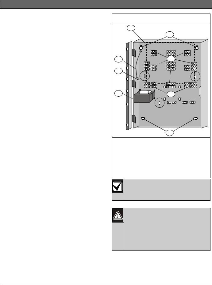
Refer to Figure 1 for the location of the major items on the FPD-7024 Control Board.
Figure 1: FPD-7024 Control Board
|
|
|
|
|
|
|
|
|
R2 |
|
|
|
|
|
|
|
|
|
|
HR2 |
|
11 |
|
|
|
|
|
|
|
|
HT2 |
1 |
AUX- |
|
|
|
|
|
|
T2 |
|||
|
|
|
|
|
|
R1 |
||||
AUX+ |
|
|
|
|
|
|
||||
|
|
|
|
|
|
|
|
|
RH1 |
|
|
N |
A+ |
|
|
|
|
|
|
TH1 |
|
|
CA B+ |
|
|
|
|
|
|
T1 |
|
|
10 |
1 |
B- |
|
|
|
|
|
|
NC3 |
|
|
A- |
|
|
|
|
|
|
COM3 |
|
|
|
|
|
|
|
|
|
|
|
||
N A+ |
|
|
|
|
|
|
NO3 |
|
||
|
A |
B+ |
|
|
|
|
|
|
NC2 |
|
|
C |
B- |
|
|
|
|
|
|
2 |
|
|
2 |
|
|
|
|
|
|
COM2 |
||
|
|
A- |
|
|
|
|
|
|
NO2 |
|
|
|
|
|
|
|
|
|
|
||
|
BAT- |
|
|
|
|
|
|
NC1 |
|
|
|
|
|
|
|
|
|
COM1 |
|
||
|
24V |
Power |
|
Trouble |
|
|
|
|||
9 |
BAT+ |
|
|
|
NO1 |
|
||||
|
|
Alarm |
|
Silenced |
|
|
SMK+ |
3 |
||
|
|
Supervisory |
Gnd Flt |
|
|
SMK- |
||||
|
|
|
|
|
|
|
|
|
|
|
|
|
|
|
|
|
|
|
|
4A+ |
|
|
|
|
|
|
|
|
|
|
4B+ |
|
|
|
|
|
|
|
|
|
|
4B- |
|
|
|
|
|
|
|
|
|
|
4A- |
|
|
|
|
|
|
|
|
|
|
3A+ |
|
|
|
|
|
|
|
|
|
|
3B+ |
|
|
|
|
|
|
|
|
|
|
3B- |
4 |
|
|
|
|
|
|
|
|
|
3A- |
|
|
|
1 |
2 |
3 |
Drill |
|
|
|
2A+ |
|
|
|
Acknowledge |
|
|
2B+ |
|||||
|
|
|
|
|
|
|
|
|
||
8 |
|
4 |
5 |
6 |
|
|
|
|
2B- |
|
|
Disable |
|
|
|
2A- |
|
||||
|
7 |
8 |
9 |
|
Silence |
|
|
1A+ |
|
|
|
|
Test |
|
|
|
1B+ |
|
|||
|
|
|
|
# |
|
|
|
|
1B- |
|
|
|
|
0 |
History |
Reset |
|
|
1A- |
|
|
|
|
|
|
|
|
|
||||
|
|
Back |
Prog |
Enter |
|
|
|
|
|
|
|
|
* |
|
|
|
|
|
|
|
|
|
|
|
|
|
|
R |
B G |
Y |
OPTION BUS |
|
|
7 |
|
6 |
5 |
|
|
|
|
|
1. |
Telco Terminal Strip |
7 - |
Keypad |
|
2 - |
Relay Terminal Strip |
8 - |
D7039 MUX Expansion Module Connector Pins |
|
3 - Smoke Power Terminal Strip |
9 - |
LCD Display |
|
|
4 - Zone Input Terminal Strip |
10 - NAC Terminal Strip |
|||
5 - Option Bus Terminal Strip |
11. |
Auxiliary Power Terminal Strip |
||
6 - FPC-7034 Point Expander Connector Pins |
|
|
|
|
Bosch Security Systems, Inc. | 9/08 | F01U008458-01 |
7 |
FPD-7024 | Operation and Installation Guide | |
1.0 |
Overview |
|
|
|
1.2Components
1.2.1On-board Conventional Points
All on-board points and points implemented with the FPC-7034 work with twoor four-wire detectors. The system has an optional alarm verification feature.
Table 1: Two-Wire Circuits
|
|
Number of two-wire circuits |
Four circuits, expandable to |
|
eight using an FPC-7034 |
|
Expander |
Type of Circuit |
Class B, Style 4 and Class |
|
A, Style 6 as needed) |
EOL Resistor |
2.21 kΩ (P/N: 25899 or |
|
F01U034504), |
|
UL listed |
Supervisory Existing |
8 to 20 mA |
Required Existing for Alarm |
25 mA |
|
|
Maximum Short Circuit |
45 mA |
Existing |
|
Maximum Line Resistance |
150Ω |
|
|
Circuit Voltage Range |
20.4 to 28.2 VDC |
Maximum Detectors per |
20 detectors (two-wire) |
Point |
|
|
|
Total Detector Standby |
3 mA maximum |
Existing |
|
Response Time* |
Either fast (500 ms) or |
|
programmable (from 1 to 89 |
|
seconds) |
|
|
Dirty Detector Monitoring |
Implements Bosch Security |
|
Systems, Inc. Chamber |
|
Check® and GE Interlogix, |
|
Inc. CleanMe™ protocol to |
|
monitor conventional loops |
|
for dirty detectors. |
|
|
* Refer to Section 6.4 on page 82.
All on-board points, and points activated with the FPC-7034 Four Point Expander, are continuously monitored for detectors signaling a dirty condition using the Bosch Security Systems, Inc. Chamber Check and GE Interlogix, Inc. CleanMe protocols. To prevent nuisance reports, a two-minute delay occurs before a dirty detector is annunciated. A sixminute delay occurs after the detector restores from the dirty condition before the control panel restores the condition.
1.2.2Off-board Addressable Points (with D7039 Multiplex Expansion Module)
The D7039 Multiplex Expansion Module adds:
•Two Class B, Style 4 or one Class A, Style 6 Signaling Line Circuits (SLCs)
•Each point is individually supervised for proper connection to the common bus (when over ten points are troubled, up to ten troubles are shown per bus and the balance of the troubles is indicated by a common bus failure message).
•Response time can be set to fast, or programmed from 1 to 89 seconds.
•Input points on the SLCs are implemented with a D7042 Eight Input Remote Module.
1.2.3Enclosure Housing
The standard enclosure is 18 ga., cold-rolled steel, and measures 20.75 in. x 15 in. x 4.25 in. (52.7 cm x 38.1 cm x 10.8 cm). A keyed lock is included, and the LEDs and LCD display are visible through the door.
1.2.4Remote LCD Keypads
Maximum number of keypads: Four FMR-7033 LCD Fire Keypads.
Wiring Requirements: Refer to Section 2.2 Option Bus Wiring Requirements on page 19.
1.2.5Remote LED Annunciators
Maximum number of annunciators: Eight D7030 eight-zone LED Annunciators.
Wiring Requirements: Refer to Section 2.2 Option Bus Wiring Requirements on page 19.
1.2.6D7032 with the D7030X Use
When a D7032 Eight-Zone LED Annunciator Expander is connected to the D7030X, eight additional LED zones appear. This allows the D7030X/D7032 combination to show 16 LED zones. Up to eight D7030X/D7032 combinations can be connected to the FPD-7024 Fire Alarm Control Panel. Refer to Table 2 on page 9 for zones shown by each D7030X/D7032 combination.
Each D7030X processes 16 zones of information. If no D7032 is attached, only the lower eight zones are shown.
The column labeled Shown on D7030X” In Table 2 on page 9 applies regardless if an attachment of a D7032 to any D7030X is made.
Bosch Security Systems, Inc. | 9/08 | F01U008458-01
8
FPD-7024 | Operation and Installation Guide | |
1.0 |
Overview |
|
|
|
Table 2: |
LED Assignments for LED Annunciators 4 and 8 |
|||
|
|
|
|
|
|
|
|
|
|
D7030X |
Zones |
Shown on |
Shown on |
COMMENTS |
|
Covered |
7030X |
D7032 (if |
|
|
|
|
attached) |
|
1 |
1 to 16 |
1 to 8 |
9 to 16 |
Combination with lowest option bus address (such as Address 1) |
2 |
17 to 32 |
17 to 24 |
25 to 32 |
Combination with second lowest option bus address (such as |
|
|
|
|
Address 2) |
3 |
33 to 48 |
33 to 40 |
41 to 48 |
Combination with third lowest option bus address (such as |
|
|
|
|
Address 3) |
4 |
49 to 64 |
49 to 56 |
57 to 64 |
Combination with fourth lowest option bus address (such as |
|
|
|
|
Address 4) |
|
|
|
|
|
5 |
1 to 16 |
1 to 8 |
9 to 16 |
Fifth combination repeats first combination |
6 |
17 to 32 |
17 to 24 |
25 to 32 |
Sixth combination repeats second combination |
|
|
|
|
|
7 |
33 to 48 |
33 to 40 |
41 to 48 |
Seventh combination repeats third combination |
8 |
49 to 64 |
49 to 56 |
57 to 64 |
Eighth combination repeats forth combination |
|
|
|
|
|
Refer to Table 3 for the LED display for Zones 49 to 64.
Table 3: LED Display for Zone 49 to 64
LED |
Zone |
Description |
1 |
49 |
User defined |
|
|
|
2 |
50 |
User defined |
3 |
(reserved) |
|
4 |
52 |
General fire alarm monitor waterflow (non-silencable) |
5 |
53 |
General fire alarm monitor (silencable) |
|
|
|
6 |
(reserved) |
|
7 |
55 |
General Supervisory (silencable) |
|
|
|
8 |
56 |
General Waterflow (silencable) |
9 |
(reserved) |
|
10 |
58 |
General supervisory alarm (non-silencable) |
11 |
(reserved) |
|
|
|
|
12 |
(reserved) |
|
13 |
61 |
General waterflow alarm (non-silencable) |
|
|
|
14 |
(reserved) |
|
15 |
63 |
General alarm monitor waterflow (non-silencable) |
16 |
(reserved) |
|
1.2.7Communicator
The communicator can report to two phone numbers or IP addresses with full single, double, and back-up reporting. Communicates in SIA, Modem IIIa2, Contact ID, BFSK, and 3/1 and 4/2 Tone burst formats.
The communicator must be enabled and configured to operate. The communicator and phone line monitors are disabled in the default factory configuration.
Bosch Security Systems, Inc. | 9/08 | F01U008458-01 |
9 |
FPD-7024 | Operation and Installation Guide | |
1.0 |
Overview |
|
|
|
Phone Line and Phone Number/IP Selection: To ensure the delivery of critical reports, the fire panel has two phone lines and two phone numbers or IP addresses that can be used for reporting. Reports can be directed to one or both of two phone numbers or IP addresses using the Report Steering feature (refer to Section 5.6.3 Report Steering on page 65) in the control panel programming. Note that Account Number 1 is used with Phone Number/IP 1, and Account Number 2 is used with Phone Number/IP 2. Except for test reports, the control panel automatically selects the phone line or IP address to use. If the report is not successful after two attempts on Line 1, the control panel automatically switches and uses Phone Line 2. One exception is when test reports (manual or automatic) are sent. Test reports are sent every 4 hours to 28 days. Each time a Test report is sent, the control panel alternates phone lines. This happens even if the monitor says the line is bad. If the user sends two manual test reports both phone lines can be tested. The first report uses one line and the second uses the other line. During normal operation, the automatic test uses a different line each day.
Because the control panel automatically selects which line to use, both phone lines must use the same dialing sequences for sending reports. For example, a line that requires a 9 to be dialed for an outside line cannot be paired with a line that does not require a 9.
PBX lines and ground start phone lines do not comply with NFPA requirements for digital communication.
While the control panel is idle, the FACP monitors the primary and alternate telephone lines by monitoring the line for trouble. The FACP monitors each line every 12 seconds. When a trouble still exists after three samples (36 seconds), the FACP sends a trouble report and activates the yellow trouble LED and trouble relay.
If the central station receives the automatic test report only every other day, this indicates that one phone line at the protected premises is inoperative. Correct this condition immediately, because other critical reports can be delayed when the communicator is trying to send the test signal through the inoperative phone line (once each 48 hours).
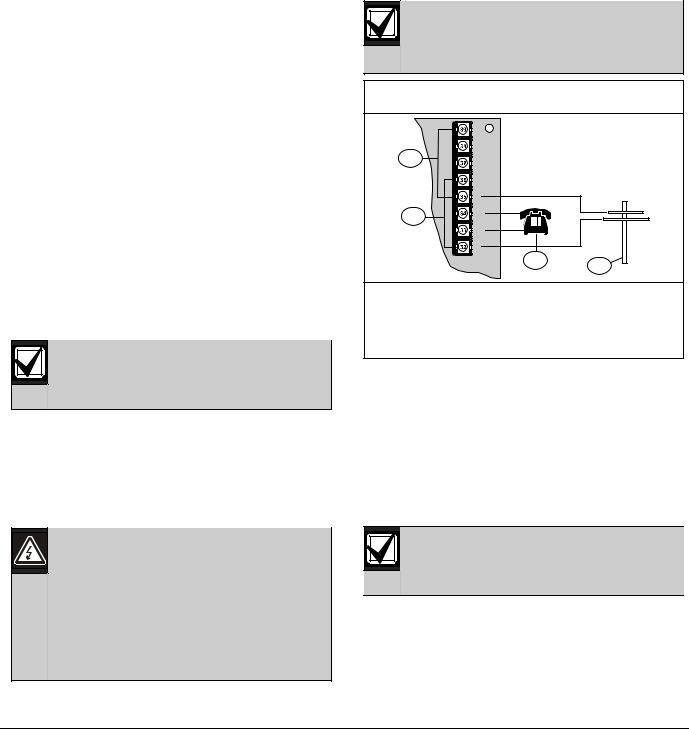
Supplemental Reporting: While two independent phone lines are required for UL864 Central Station service, the FACP can be configured with one phone line if the control panel is used only for supplemental reporting on a local, remote station or auxiliary system.
Connect a jumper from T1 to T2 and R1 to R2 if the control panel is installed with only one phone line. Refer to Figure 2.
Control panel reports can be delayed if the dialer outputs are not connected together on an installation where the control panel has only one phone line
Figure 2: Supplemental Reporting
|
R2 |
|
1 |
HR2 |
|
HT2 |
|
|
|
|
|
|
T2 |
|
|
R1 |
|
2 |
RH1 |
|
|
|
|
|
TH1 |
|
|
T1 |
|
|
3 |
4 |
|
|
1 - Jumper from R1 to R2
2 - Jumper from T1 to T2
3 - House phone
4 - Telco Line
1.2.8Users
The system allows up to 16 individual users, or up to 100 users when the D7039 is installed. A personal identification number (PIN) the four-digit code entered at the keypads, and an authority level to determine which functions can be performed (refer to Section 5.2.1 Personal Identification Numbers on
page 41) can be assigned to each user.
1.2.9 |
Lightning Protection |
|
This system is intended for installation |
|
entirely within one building. |
Metal-oxide varistors (MOV) and spark gaps provide protection from lightning surges and static discharges.
Bosch Security Systems, Inc. | 9/08 | F01U008458-01
10
FPD-7024 | Operation and Installation Guide | |
1.0 |
Overview |
|
|
|
1.2.10 Backup Battery Calculation
Use Table 4 to calculate the standby battery capacity required by NFPA when using the FPD-7024.
Table 4: Standby Battery Capacity Calculations
|
|
|
|
|
|
|
|
|
|
|
Device |
Quantity |
Standby |
Total |
|
Alarm |
Total Alarm |
||
|
|
|
Existing/Device |
Standby |
|
Existing/Device |
|
||
|
FPD-7024 Control panel |
1 |
200 mA |
200 mA |
|
380 mA |
|
380 mA |
|
|
FPC-7034 Four-Point Expander |
|
44 mA |
|
156 mA |
|
|||
|
|
|
|
|
|
|
|
||
|
D7035/B Octal Relay1 |
|
8 Ma + 30 mA2 |
|
|
8 Ma + 30 mA2 |
|
|
|
|
D7048/B Octal Driver Module |
|
10 mA |
|
10 mA |
|
|||
|
|
|
|
|
|
|
|
||
|
FMR-7036 Annunciator Keypad |
|
80 mA |
|
|
100 mA |
|
|
|
|
D7030X Eight-Point LED Annunciator1 |
|
27 mA |
|
|
132 mA |
|
||
|
|
|
|
|
|
|
|
||
|
D7030X-S2 Eight-Point LED Annunciator |
|
35 mA |
|
|
175 mA |
|
|
|
|
D7030X-S8 Eight-Point LED Annunciator |
|
35 mA |
|
175 mA |
|
|||
|
|
|
|
|
|
|
|
||
|
D7032 Eight-Point LED Annunciator |
|
1 mA |
|
|
90 mA |
|
|
|
|
Expander |
|
|
|
|
|
|
|
|
|
FMR-7033 Keypad1 |
|
80 mA |
|
|
100 mA |
|
||
|
|
|
|
|
|
|
|
||
|
D7039 MUX Expansion Module |
|
150 mA |
|
|
150 mA |
|
|
|
|
D7042/B Addressable Eight Point Input |
|
18 mA |
|
18 mA |
|
|||
|
|
|
|
|
|
|
|
||
|
D7050 MUX Photoelectric Smoke |
|
0.50 mA |
|
|
0.56 mA |
|
|
|
|
Detector |
|
|
|
|
|
|
|
|
|
D7050TH MUX Photoelectric Smoke |
|
0.50 mA |
|
|
0.56 mA |
|
||
|
Detector |
|
|
|
|
|
|
|
|
|
FMM-7045 Mux Pull Station |
|
0.55 mA |
|
|
0.55 mA |
|
|
|
|
D7044 Mux Single Input Fire |
|
0.55 mA |
|
0.55 mA |
|
|||
|
|
|
|
|
|
|
|
||
|
D7044M Mux Mini Contact Module |
|
0.55 mA |
|
|
0.55 mA |
|
|
|
|
D7052 Mux Dual Input Fire |
|
0.55 mA |
|
0.55 mA |
|
|||
|
|
|
|
|
|
|
|
||
|
D7053 Mux I/O Module Fire |
|
0.70 mA |
|
|
0.70 mA |
|
|
|
|
Smoke Detectors |
|
|
|
|
|
|
|
|
|
|
|
|
|
|
|
|
|
|
|
Bells, Horns, and so on |
|
|
|
|
|
|
|
|
|
Other Sensors |
|
|
|
|
|
|
|
|
|
|
|
|
|
|
|
|
|
|
|
Other |
|
|
|
|
|
|
|
|
|
|
|
Grand Total |
|
|
Grand Total |
|
||
|
|
|
Standby Existing |
|
|
Alarm Existing |
|
||
1 The 24 VDC existing requirements for the D7030X, FMR-7033 and D7035 are shown at 75% of the 12 VDC level shown on the specification sheets for these models. The FPD-7024 regulates 24 VDC power from the battery to 12 VDC for these accessories.
2Add 30 mA for each relay activated
Bosch Security Systems, Inc. | 9/08 | F01U008458-01 |
11 |
FPD-7024 | Operation and Installation Guide | |
1.0 |
Overview |
|
|
|
The units shown in Table 5 are Amp hours (Ah), and the figures include a 20% derating factor.
Table 5: Required Battery Size Calculation
|
|
|
|
|
|
|
|
Grand Total Standby Existing (in amps) |
CS |
|
|||
|
|
|
|
|
|
|
|
Total Hours of Standby Required (usually 24 or 60): |
|
HS |
|
|
|
|
Total Standby Capacity (multiply CS X HS) |
TS= CS X HS |
|
|||
|
|
|
|
|
|
|
|
Grand Total Alarm Existing (in amps) |
CA |
|
|||
|
|
|
|
|
||
|
Total Hours of Alarm Time Required (usually 0.083 or 0.25): |
|
HA |
|
|
|
|
Total Standby Capacity (multiply CA X HA) |
TA= CA X HA |
|
|||
|
|
|
|
|
|
|
|
Total Capacity Required (add TA + TS): |
|
TC = TA + TS |
|
|
|
|
|
|
|
|
|
|
|
Required Capacity with 20% Derating (TC X 1.2) |
|
C = TC X 1.2 |
|
|
|
|
|
|
|
|
|
|
|
|
|
|
|
|
|
|
|
|
|
|
|
|
The required battery size to support the system can be calculated using Table 6 and Table 7 on page 13.
1.2.11 Standby Existing Load
Use Table 6 to estimate the size of the battery required to support the standby load, then use Table 7 on page 13 to estimate the size of the battery required to support the alarm load. Add the results together for the total battery size. Select the next larger standard battery for the system. If the results show a requirement for a battery over 40 Ah, reduce the existing or add an external regulated fire protective signaling power supply.
Table 6: |
Standby Load Battery Size (Ah) |
|
|
|
|
|
|
|
|
|
|
|
|
|
|
|
|
Standby Load Battery Size Chart |
|
Capacity Required for |
Capacity Required for |
Capacity Required for |
|
|
|
|
24 Hours |
48 Hours |
60 Hours |
|
|
|
|
|
|
Grand Total Standby Existing |
|
|
|
|
|
100 to 200 mA |
|
5.8 |
11.5 |
14.4 |
|
|
|
|
|
|
|
201 to 300 mA |
|
8.6 |
17.3 |
21.6 |
|
301 to 400 mA |
|
11.5 |
23.0 |
28.8 |
|
|
|
|
|
|
|
401 to 500 mA |
|
14.4 |
28.8 |
36.0 |
|
501 to 600 mA |
|
17.3 |
34.6 |
X |
|
|
|
|
|
|
|
601 to 700 mA |
|
20.2 |
X |
X |
|
701 to 800 mA |
|
23.0 |
X |
X |
|
|
|
|
|
|
|
801 to 900 mA |
|
25.9 |
X |
X |
|
901 to 1000 mA |
|
28.8 |
X |
X |
|
|
|
|
|
|
|
1001 to 1100 mA |
|
31.7 |
X |
X |
|
|
|
|
|
|
|
Bosch Security Systems, Inc. | 9/08 | F01U008458-01
12

FPD-7024 | Operation and Installation Guide | |
1.0 |
Overview |
|
|
|
Table 7: |
Alarm Load Battery Size (Ah) |
|
|
|
|
|
|
|
|
|
|
|
|
|
|
|
|
Alarm Load Battery Size Chart |
Capacity |
Capacity |
Capacity |
|
Capacity |
|
Capacity |
|
|
|
Required for 5 |
Required for 10 |
Required for 15 |
|
Required for 30 |
|
Required for 45 |
|
|
Minutes |
Minutes |
Minutes |
|
Minutes |
|
Minutes |
Grand Total Standby Existing |
|
|
|
|
|
|
|
|
|
|
|
|
|
|
|
||
250 to 500 mA |
0.1 |
0.1 |
0.2 |
|
0.3 |
|
0.5 |
|
501 to 999 mA |
0.1 |
0.2 |
0.3 |
0.6 |
|
0.9 |
||
|
|
|
|
|
|
|
|
|
1.0 to 1.5 A |
|
0.2 |
0.3 |
0.5 |
|
0.9 |
|
1.4 |
1.6 to 2.0 A |
|
0.2 |
0.4 |
0.6 |
1.2 |
|
1.8 |
|
|
|
|
|
|
|
|
|
|
2.1 to 2.5 A |
|
0.3 |
0.5 |
0.8 |
|
1.5 |
|
2.3 |
2.6 to 3.0 A |
|
0.3 |
0.6 |
0.9 |
1.8 |
|
2.7 |
|
|
|
|
|
|
|
|
|
|
3.1 to 3.5 A |
|
0.4 |
0.7 |
1.1 |
|
2.1 |
|
3.2 |
3.6 to 4.0 A |
|
0.4 |
0.8 |
1.2 |
2.4 |
|
3.6 |
|
|
|
|
|
|
|
|
|
|
Bosch Security Systems, Inc. | 9/08 | F01U008458-01 |
13 |

FPD-7024 | Operation and Installation Guide | |
1.0 |
Overview |
|
|
|
1.2.12 Compatible Devices
Table 8: Compatible Devices
Device
D7030 Eight Point LED
Annunciator
D7030X Eight Point LED
Annunciator
D7030X-S2 Eight Point
LED Annunciator
D7030X-S8 Eight Point
LED Annunciator
D7032 Eight Point LED
Annunciator Expander
FMR-7033 Alphanumeric
LCD Keypad
FPC-7034 Four Point
Expander
D7035/B Octal Relay
Module
FMR-7036 Fire
Annunciator Keypad
FPP-RNAC-8A-4C Remote
NAC Power Supply
D7039 Multiplex
Expansion Module
D7042/B Eight-Input
Remote Module
D7048/B Octal Driver
Module
FMM-7045 Mux Pull
Station
D7044 Mux Single Input
Fire
D7044M Mux Mini Contact
Module
Function
Identifies the location of a fire alarm for up to eight zones allowed per system.
Identifies the location of a fire alarm for up to eight zones allowed per system.
An eight-zone LED annunciator, of which two zones are reserved for supervisory functions. It has Power and Trouble LEDs plus eight-zone LEDs that can be labeled individually.
An eight-zone LED annunciator, of which all eight zones are reserved for supervisory functions. It has Power and Trouble LEDs plus eight-zone LEDs that can be labeled individually.
Attaches to a D7030X and identifies the location of a fire alarm for eight additional zones.
Connects up to four-keypads per system.
Allows the FPD-7024 Control Panel to support four additional points. The FPC-7034 plugs into the control panel and provides four Class B, Style 4 loops that are identical in characteristics to the loops on the control panel. One FPC-7034 is allowed per system.
Provides eight Form C relay outputs for addition to the system. The outputs are programmable and can be activated by system events. Each output operates independently of the other seven outputs for complete flexibility. The D7035 connects to the option bus; up to two are allowed per system. Refer to the D7035 Installation Guide (P/N: 37280) for required enclosure modification. The D7035B comes installed on a mounting skirt.
Establishes the location of a fire alarm.
Adds four NFPA 72 Class B, Style Y Notification Appliance Circuits through the option bus and is supervised by the control panel. The FPP-RNAC-8A-4C connects to the option bus of the FPD-7024 control panel and up to four are allowed per system.
Provides either 2 two-wire (Class B, Style 4) multiplex buses or 1 four-wire (Class A, Style 6) multiplex bus. In Class A mode, up to 120 addressable points can be added. In Class B Mode, up to 247 addressable points can be added. The D7039 connects directly to the control panel. One is allowed per system.
Provides eight Class B, Style 4 input points. Connect up to 15 modules to MUX Bus A, and 15 on MUX Bus B. The D7042 is powered by 12 VDC supplied by the option bus power terminals, in addition to the two-wire data connection. The D7042 can not be used on a signal line circuit (SLC) configured for Class A, Style 6 operation.
Provides eight open collector transistor outputs for addition to the FPD-7024 Fire Alarm Control panels. It connects to the control panels through the option bus.
UL Listed fire alarm initiating device.
Connects a contact device to the multiplex bus of the FPD-7024 with a supervised local loop. The D7044 draws operating power from the FPD-7024.
Connects a contact device to the multiplex bus of the FPD-7024 with a supervised input loop. The D7044 draws operating power from the FPD-7024.
Bosch Security Systems, Inc. | 9/08 | F01U008458-01
14

FPD-7024 | Operation and Installation Guide | |
1.0 |
Overview |
|
|
|
Table 8: Compatible Devices (continued)
D7052 Mux Dual Input Fire
D7053 Mux I&O Module
Fire
D7050/TH Mux Smoke
Detector
Connects to the multiplex bus of the FPD-7024 and provides two supervised input zones for connecting conventional normally-open inputs. The D7052 draws operating power from the FPD-7024.
Connects to the multiplex bus of the FPD-7024 and implements a supervised local loop, and a Form C relay output. Up to 20 modules can be connected to each MUX bus. The D7053 draws operating power from the FPD-7024.
The D7050/TH is a photo-electric smoke detector with a heat option. It connects to the multiplex bus of the FPD-7024. The D7050 draws operating power from the FPD-7024.
Table 9: |
Address Restrictions for the D7042, D7052, and D7053 |
|
|
|
|||||
|
|
|
|
|
|
|
|
|
|
|
|
|
|
|
|
|
|
|
|
Install D7042 modules only at addresses: |
|
|
|
|
|
|
|||
9 |
|
17 |
25 |
33 |
|
41 |
49 |
57 |
65 |
|
|
|
|
|
|
|
|
|
|
73 |
|
81 |
89 |
97 |
|
105 |
113 |
121 |
129 |
|
|
|
|
|
|
|
|
|
|
137 |
|
145 |
153 |
161 |
|
169 |
177 |
185 |
193 |
|
|
|
|
|
|
|
|
|
|
201 |
|
209 |
217 |
225 |
|
233 |
241 |
|
|
|
|
|
|
|
|
|
|
|
|
Do not install D7052 and D7053 modules at these addresses |
|
|
|
|
|||||
|
|
|
|
|
|
|
|
|
|
16 |
|
24 |
32 |
40 |
|
48 |
56 |
64 |
72 |
|
|
|
|
|
|
|
|
|
|
80 |
|
88 |
96 |
104 |
|
112 |
120 |
128 |
136 |
|
|
|
|
|
|
|
|
|
|
144 |
|
152 |
160 |
168 |
|
176 |
184 |
192 |
200 |
|
|
|
|
|
|
|
|
|
|
208 |
|
216 |
224 |
232 |
|
240 |
248 |
255 |
|
|
|
|
|
|
|
|
|
|
|
Bosch Security Systems, Inc. | 9/08 | F01U008458-01 |
15 |
FPD-7024 | Operation and Installation Guide | 1.0 |
Overview |
|
|||
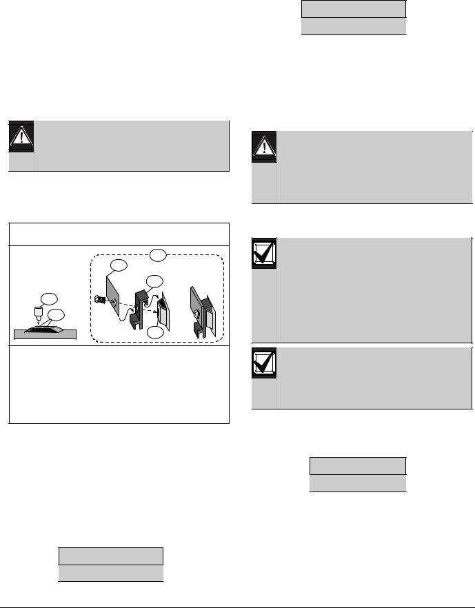
1.3 |
Parts List |
Figure 3: |
Enclosure Installation |
||
• |
One FPD-7024 Control/Communicator in static- |
|
1 |
|
|
|
resistant bag |
|
|
||
|
|
|
2 |
||
• |
One enclosure with transformer |
|
|
||
|
|
|
|||
• |
One hardware pack |
|
|
|
|
• |
One enclosure lock, washer, and keys |
|
|
|
|
• |
Six end-of-line (EOL) resistors |
7 |
|
3 |
|
The hardware necessary for installing the control |
|
|
|
||
panel in the enclosure is located in the hardware |
6 |
|
|
||
pack. |
|
|
|
||
1.4 |
Installing the Enclosure |
|
|
|
|
1. |
Using the enclosure as a template, mark the top |
|
|
|
|
|
mounting holes on the mounting surface |
5 |
|
4 |
|
|
(Figure 3). |
|
|
|
|
2. |
Start the mounting screws (not supplied) for |
|
|
|
|
|
these two holes. |
|
|
|
|
3. |
Slide the enclosure onto these screws so that the |
|
|
|
|
|
screws rest on the thinner section of the holes. |
|
|
|
|
4. |
Tighten the screws. |
|
|
|
|
5. |
Install and tighten the remaining two screws in |
|
|
2 |
|
|
the bottom mounting holes. |
1 - Control panel location |
|||
6. |
Knock out the desired wire entrances on the |
||||
2 - |
Mounting holes |
||||
|
enclosure. |
3 - Retainer holes for standoffs |
|||
|
|
||||
|
|
4 - Retainer holes for support posts |
|||
|
|
5 - |
Transformer |
||
|
|
6 - |
Stud |
|
|
|
|
7 - |
Ground wire |
||
|
|
|
If using the knockouts located at the |
||
|
|
|
bottom of the enclosure install batteries in |
||
|
|
|
a separate enclosure. |
||
|
|
1.5 |
Installing the FPD-7024 |
||
|
|
|
The control circuit board in the FPD-7024 |
||
|
|
|
is static sensitive. Touch ground before |
||
|
|
|
handling the control board. This discharges |
||
|
|
|
any static electricity in your body. For |
||
|
|
|
example, run the ground wire to the |
||
|
|
|
enclosure before handling the control |
||
|
|
|
circuit board. Continue touching the |
||
|
|
|
enclosure while installing the control board. |
||
|
|
1. |
Insert the three support posts in the enclosure’s |
||
|
|
|
retainer holes. Refer to Figure 3 above and |
||
|
|
|
Figure 4 on page 17. |
||
Bosch Security Systems, Inc. | 9/08 | F01U008458-01
16
FPD-7024 | Operation and Installation Guide | |
1.0 |
Overview |
|
|
|
2.Press the 1/8 in. nylon standoffs
(P/N: F01U034705) into the retainer holes.
3.Slide the top of the control panel onto the retainer tabs (the slots under the top of the frame). When the control panel is in the retainer tabs, it rests on the posts.
4.Secure the bottom of the circuit board by inserting and tightening the screws at the two bottom corners through the support posts and the retainer holes Figure 4.
Connect the supplied ground wire between the door and the enclosure using the supplied nuts before the circuit board is installed.
A second ground wire is provided for connecting the AC power ground. Both grounds connect to the stud in the enclosure to the left of the circuit board. Refer to Figure 3 on page 16.
Figure 4: |
Standoff and Support Post Installation |
||
|
|
|
3 |
|
|
4 |
|
|
|
|
5 |
|
1 |
|
|
|
|
2 |
= |
|
|
|
|
|
|
|
6 |
1 - 1/8 in. nylon standoff |
|
||
2 - |
Retainer holes |
|
|
3 - Support post assembly |
|
||
4 - Corner of circuit board |
|
||
5 - |
Support post |
|
|
6 - Retainer hole in enclosure |
|
||
1.6Installing Optional Equipment
Two expansion options connect directly to the control panel, and are automatically detected and supervised when the control panel is powered:
•FPD-7034 Four Point Expander
•D7039 Multiplex Expansion Module
When the control panel is powered after installing one of these options, the control panel displays one of the following windows:
4Z EXP DETECTED
PRESS ENTER KEY
MUX DETECTED
PRESS ENTER KEY
Press the [#/Enter] key to confirm the installation of the device and automatically set it up for supervision.
If the [#/Enter] key is not pressed during the powerup time-out period, the control panel resumes operation using the last confirmed status of the affected expander and displays an installation error condition.
Expansion devices such as point expanders and multiplex expanders are disabled if they are removed from the control panel configuration after installation. You cannot disable supervision of these devices when they are installed.
Refer to the installation instructions for these expanders for additional information.
When the D7039 Multiplex Expansion Module is first installed, the system displays an EEPROM fault. Execute the default procedure to synchronize the EEPROM on the expansion module to the EEPROM in the control panel. Remove power to the control panel, then reapply power and reinstall option bus devices after the default procedure.
Replacing a D7039 Multiplex Expansion Module causes the loss of programming of expansion points and PINs. Reprogram all multiplex point and PINs if you replace the D7039.
When the D7039 is first installed, or anytime the control panel is powered with a D7039 that has no points programmed, the system automatically starts the multiplex auto-programming process:
AUTO PROGRAM?
:YES(1)/NO(0)
Pressing the [1] key starts auto-programming, and pressing [0/Prog] allows the control panel to continue normal startup. The menu automatically closes with NO selected if no key is pressed after several minutes. Refer to Section 5.9.4 Auto Program on page 74 for detailed instructions on the autoprogramming mode.
Bosch Security Systems, Inc. | 9/08 | F01U008458-01 |
17 |

FPD-7024 | Operation and Installation Guide | |
2.0 |
Control Panel Terminal Connections |
|
|
|
2.0 Control Panel Terminal Connections
Figure 5: FPD-7024 Control Panel Terminal Connections
Incorrect connections may result
in damage to the unit and personal injury.
Before servicing this equipment, remove all
-power including the transformer, battery
and phone lines.
Shared cable is not recommended for |
option bus, telephone or NAC wiring. |
Typical Fire Wiring
Typical 2-wire smoke detector wiring (supervised)
1A+ |
|
|
|
|
|
|
|
|||||
1B+ |
|
|
|
|
|
|
|
|
CLASS A |
|||
|
|
|
|
|
|
|
|
|||||
1B- |
|
|
|
|
|
|
|
|
|
STYLE D |
||
1A- |
|
|
|
|
|
|
|
|||||
|
|
|
|
EOL |
||||||||
1A+ |
|
|
|
|||||||||
|
Resistor |
|||||||||||
1B+ |
|
|
|
|
|
|
|
|
|
|
|
CLASS B |
1B- |
|
|
|
|
|
|
|
|
|
|
|
STYLE B |
|
|
|
|
|
|
|
|
|
|
|
|
|
1A- |
|
|
|
|
|
|
||||||
Typical 4-wire smoke detector wiring.
SMK+

 CLASS A SMK- STYLE D
1A+
1B+
1B-
1A-
SMK+ |
|
SMK- |
|
1A+ |
|
1B+ |
|
1B- |
|
1A- |
CLASS B |
|
STYLE B |
Red |
|
|
|
NC |
||
|
|
|
|
|
|
AC Power 2 |
|
|
|
|
|
|
NC |
Brown |
|
|
|
|||
|
|
|
AC Power 1 |
|||
|
|
|
|
|
|
|
For connection to listed power limited Class 2 or Class 3 sources only.
switched unsupervised
unsupervised |
Relay 3 |
unsupervised |
Contacts |
rated at Relay 2 |
|
|
5.0 A, 24 V |
unsupervised |
Relay 1 |
Smoke Power: 24 V, 1.0 A max. (filtered) Refer to Technogram P/N: F01U010790 for compatible devices.
Earth Ground
Input Points 1-4:
(supervised) Points are intended for connection of normally-open/ normally-closed alarm contacts. They may also be used for compatible two-wire smoke detectors.
All EOL resistors are 2.21 k Ω, P/N: 25899 Bosch,UL listed.
Initiating devices are Class B, Style B or Class A , Style D.
Two-Wire Compatibility Identifier “A”.
NC3 COM3 NO3
NC2
COM2
NO2
NC 1 COM1 NO 1
SMK+ SMK-
4A+
4B+
4B-
4A-
3A+
3B+
3B-
3A-
2A+
2B+
2B-
2A-
1A+
1B+
1B-
1A-
R2 |
HR2 |
HT2 |
T2 |
R1 |
RH1 |
TH1 |
T1 |
Phone Line 2
(Supervised)
Phone Line 1
(Supervised)
 Black
Black
Battery # 1
|
|
|
|
|
|
COM |
|
|
|
|
|
|
|
|
|
+12V |
DATA |
|
|
|
|
|
Silenced |
|
|
BOSCH |
|
|
|
|
|
|
Alarm |
|
|
|
|
|
|
|
|
|
Supervisory |
|
|
|
|
|
|
|
|
|
Trouble |
|
|
|
|
|
|
|
|
|
|
TEST WEEKLY |
|
|
|
|
|
|
|
|
|
|
|
Silence |
|
|
|
|
|
|
1 |
2 |
3 |
ACK |
|
|
|
|
|
|
4 |
5 |
6 |
Reset |
|
|
|
Yellow |
|
DX4020 |
Back* |
Prog |
Enter |
Drill |
|
|
|
|
|
|
7 |
8 |
9 |
|
|
|
|
(supervised) |
|
|
|
0 |
# |
Disable |
|
|
|
White |
|
|
History |
|
Test |
|
|
|
|
|
Black |
|
|
|
|
R |
B G |
Y |
OPTION BUS |
All wiring except battery terminal and |
|
|
|
|
|||||
primary AC power is power-limited. |
|
|
|
|
|
|
|
Supervised, Class B, |
|
Primary AC and battery wires must be |
|
|
|
|
|
|
|
||
separated from other wires by at least |
|
|
|
|
|
|
|
Style 4, 500 mA , Max. |
|
¼ in. (64 mm) and tied to prevent |
|
|
|
|
|
|
|
|
|
movement. |
unswitched |
|
|
|
|
|
|
|
|
|
|
unsupervised |
AUX- |
|
|
|
|
|
|
Aux. Power: 24 V, 1.0 A max. |
AUX+ |
|
(unfiltered) |
||
|
|
|
|
|
|
|
|
NOTIFICATION APPLIANCE CIRCUIT: |
|
|
|
|
|
|
NAC 1+ +24 V while in alarm; ground while in standby. |
|
(-) |
(-) (+) |
|
|
A+ N |
NAC 1- |
Ground while in alarm; supervisory voltage while in standby. |
|
|
|
CLASS B |
EOL |
B+ A |
|
NOTIFICATION APPLIANCE CIRCUIT: |
|
|
Red |
STYLE Y (supervised) |
B- |
C |
|
||
|
1 |
NAC 2+ +24 V while in alarm; ground while in standby. |
|||||
|
|
|
|
||||
|
|
|
|
A- |
|
NAC 2- |
Ground while in alarm; supervisory voltage while in standby. |
|
|
|
|
|
|
||
|
|
|
|
|
|
BAT - |
BATTERIES: |
|
|
|
|
|
|
Requires two 12 V batteries, in series, for a combined voltage of |
|
|
|
|
CLASS A |
A+ |
N |
BAT + |
24 V. Charge current = 1.1 A, max. |
|
Battery # 2 |
|
STYLE Z |
|
|
||
(+) |
|
|
B+ A |
|
|
||
|
|
|
B- |
C |
|
|
|
|
|
|
|
A- |
2 |
Use only indicating devices as listed on Technogram P/N: F01U010791. |
|
|
|
|
Black |
BAT- |
Do not short terminals - explosion and burn hazard. |
||
|
|
|
|
24V |
|
|
|
|
Battery # 1 |
Battery # 2 |
Red |
BAT+ |
|
|
|
|
|
|
|
|
|||
|
Backup Batteries |
|
|
|
|
|
|
Bosch Security Systems, Inc. | 9/08 | F01U008458-01
18
FPD-7024 | Operation and Installation Guide | |
2.0 |
Control Panel Terminal Connections |
|
|
|
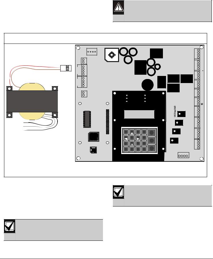
2.1Power Supply Connections
Use wire nuts to connect the primary side of the transformer (black and white wires) to the unswitched 120 V, 60 Hz or (yellow and white wires) to unswitched 240 V, 50 Hz circuit. Connect the earth ground to the threaded ground stud on the left side of the enclosure.
Place a wire nut over the unused black or yellow wire.
Figure 6: Connecting the Transformer to the FPD-7024 Circuit Board
Yellow
Primary White
Black
Connect the primary side of the transformer black and white wires to unswitched 120V, 60Hz or yellow and white wires to 240V, 50 Hz circuit using wire nuts.
AUXAUX+
N A+ AC B+ B- 1 A-
N A+ AC B+ B- 2 A-
BAT24V BAT+
|
|
R2 |
|
|
HR2 |
|
|
HT2 |
|
|
T2 |
|
|
R1 |
|
|
RH1 |
|
|
TH1 |
|
|
T1 |
|
|
NC 3 |
|
|
COM3 |
|
|
NO3 |
|
|
NC2 |
|
|
COM2 |
|
|
NO2 |
|
|
NC1 |
Power |
Trouble |
COM1 |
NO1 |
||
Alarm |
Silenced |
SMK+ |
Supervisory |
Gnd Flt |
SMK- |
|
|
4A+ |
|
|
4B+ |
|
|
4B- |
|
|
4A- |
3A+
3B+
3B-
3A-
1 |
2 |
3 |
Drill |
|
|
|
2A+ |
Acknowledge |
|
|
2B+ |
||||
|
|
|
|
|
|
||
4 |
5 |
6 |
|
|
|
|
2B- |
Disable |
|
|
|
2A- |
|||
7 |
8 |
9 |
|
Silence |
|
|
1A+ |
Test |
|
|
|
1B+ |
|||
* |
|
|
|
|
|
|
1B- |
0 |
# |
History |
Reset |
|
|
1A- |
|
|
|
|
|||||
|
|
|
|
||||
Back |
Prog |
Enter |
|
|
|
|
|
|
|
|
|
R |
B G |
Y |
OPTION BUS |
2.2Option Bus Wiring Requirements
Use 18 AWG (1.2 mm) or larger wire to connect option bus devices to the FACP. The total length of wire connected to the option bus terminals must not exceed 4,000 ft (1,219 m), regardless of the wire gauge wire used.
Shared cable is not recommended for option bus, addressable points bus, telephone, or NAC wiring.
To comply with UL, do not share supplementary devices with primary device on the option bus.
Avoid shielded or twisted pair-wire except for special applications where a reduced length of wiring (approximately 50%) is acceptable for tolerating a harsh electrical environment.
Bosch Security Systems, Inc. | 9/08 | F01U008458-01 |
19 |

FPD-7024 | Operation and Installation Guide | |
2.0 |
Control Panel Terminal Connections |
|
|
|
The length of wire allowed between the control panel and the last device on a wiring run depends on the existing drawn on that wiring run. Reducing the number of devices on a wiring run allows the individual runs to be longer. Use the guidelines in Table 10 on page 20 where devices are all of the same type on a given wire run.
Table 10: Option Bus Wiring Guidelines
|
|
|
|
Device Model Number |
Wiring Run |
Maximum Allowed Cable Length to |
Existing Draw (for reference) |
|
Number |
Last Device (#18 Wire) |
|
D7030 LED Annunciator |
1 |
1000 ft (304 m) |
175 mA |
|
|
|
|
D7030X LED Annunciator |
2 |
500 ft (152 m) |
175 mA x 2 = 350 mA |
|
|
|
|
D7030 LED Annunciator |
4 |
250 ft (76 m) |
175 mA x 4 = 700 mA |
|
|
|
|
FMR-7033 Remote Keypad |
1 |
2000 ft (608 m) |
100 mA |
|
|
|
|
FMR-7033 Remote Keypad |
2 |
1000 ft (304 m) |
100 mA x 2 = 200 mA |
|
|
|
|
FMR-7033 Remote Keypad |
4 |
500 ft (152 m) |
100 mA x 4 = 400 mA |
|
|
|
|
D7048/B Octal Driver |
1 |
500 ft (152 m) |
330 mA |
Module |
|
|
|
|
|
|
|
D7035/B Octal Remote |
2 |
250 ft (76 m) |
330 mA x 2 = 660 mA |
Relay |
|
|
|
|
|
|
|
FPP-RNAC-8A-4C |
2 |
4000 ft (1219 m) |
< 50 mA each |
|
|
|
|
DX4020 Network Interface |
1 |
750 ft (229 m) |
280 mA |
Module |
|
|
|
|
|
|
|
Where more than one type of device is installed on a given wiring run, add together the alarm existing drawn by all the devices on the wiring run to determine the maximum allowed distance between the option bus terminals on the control panel and the last device on the wire run (the device farthest from the control panel).
Add up the total alarm load for option bus devices on the wire run, and use Figure 7 to determine the maximum allowed length for the run. For example, if the total load of option bus devices on a particular run is 400 mA, the maximum length of the run can be up to 500 ft (152 m). No more than 4,000 ft (1,219 m) of wire can be connected to the option bus terminals, even if the individual lengths of the runs are all within limit.
Figure 7 shows allowed lengths for18 AWG (1.2 mm). For16 AWG (1.5 mm) wire, cable lengths can be 1.5 times longer. For14 AWG (1.8 mm) wire, cable lengths can be 2.5 times longer. The 4,000 ft (1,219 m) maximum length of connected wire still applies.
Bosch Security Systems, Inc. | 9/08 | F01U008458-01
20
FPD-7024 | Operation and Installation Guide | |
3.0 |
System Operation |
|
|
|
Figure 7: Option Bus Cable Length vs Existing Draw
2500 |
|
|
2000 |
|
|
1500 |
|
|
1000 |
|
|
500 |
|
|
0 |
300 |
500 |
100 |
||
0 |
200 |
400 |
Current Draw (mA)
3.1.2 Supervisory
3.0System Operation
3.1Modes of Operation
There are four modes of system operation for the FPD-7024: Alarm, Supervisory, Trouble, and Normal.
3.1.1Alarm
When an alarm occurs, the top line of the display shows ALARM (XXX), where XXX indicates the number of alarms. This display overrides any other system display. The second line of the display gives more instructions. When the group is entered by pushing the [6/►] key, more details of the event appear. The top line shows the number of alarms and the point that is in alarm. The bottom line alternates between the instructions and the programmed description for the affected point. The built-in sounder turns on with a steady tone, and outputs programmed to activate with the existing alarm condition(s) activate.
When the control panel is not scanning the inputs, as during smoke power reset, alarm verification delay, or on-site programming, the trouble LED flashes to indicate this condition.
When a Supervisory condition occurs, Supervisory (XXX), XXX indicates the number of supervisory conditions. The second line of the display gives more instructions. When the group is entered by pushing the [6/►] key, more details of the event appear. The bottom line alternates between the instructions and the programmed description for the affected point. The built-in sounder beeps. Outputs programmed to activate with the existing condition(s) then activate.
3.1.3Trouble
When a trouble condition occurs (such as cut wiring for a point or AC power fails), the sounder beeps every 10 seconds. The Trouble LED lights and the LCD shows TROUBLE (XXX). When the [6/►] key is pressed the group is entered and more detail appears. The system can diagnose and show a variety of trouble conditions, including those affecting the input points, NAC circuits, power, battery, system grounding, and internal operations of the fire control panel. Notify your installing company immediately if the system trouble message appears.
Press the [Silence] key to silence the system trouble beep.
3.1.4Acknowledge
When the control panel is off-normal, the control panel’s piezo (buzzer) can be silenced without silencing the NACs or resetting the control panel. Press the [ACK] button on the local or remote keypad to silence only the piezo.
Bosch Security Systems, Inc. | 9/08 | F01U008458-01 |
21 |
FPD-7024 | Operation and Installation Guide | |
3.0 |
System Operation |
|
|
|
3.1.5Fire Silence/Reset
During a fire alarm, exit from the premises immediately. Do not enter the premises unless accompanied by the appropriate emergency services' personnel, or until they have given the OK to enter.
When it is determined that there is no fire, you can silence the horns or bells to allow more investigation of the devices that initiated the alarm, or you can reset the system to return it to normal operation.
Before using the [Reset] key, determine which smoke detector sounded the alarm so that the monitoring company can check that the system is operating correctly. If the control panel is being used as an addressable control panel, use the [History] key to determine which address is in alarm.
If the system is configured to allow alarm silencing, the [Silence] key turns off the horns or bells, but does not reset the alarm status and does not return the activated input to normal service. Detectors that were activated stay in alarm and can be checked (usually by observing an LED on the device) to see which detector caused the alarm. When the detectors causing the alarm are identified, reset the system to return it to normal service.
The [Reset] key clears the system alarm status, and briefly turns off power to the detectors to reset them. This command is required after any fire alarm affecting a point programmed for latching operation (which is the normal configuration). This operation is also required to reset a Class A, Style 6 multiplex (SLC) wiring fault troubles.
The software uses a system supervisor function that automatically supervises the system software for proper operation. If the system fails, a CPU FAULT message appears, and the nature of the failure can be optionally recorded in the history buffer. To enable history buffer recording for CPU faults, program Output Zone D of onboard Relay 2 to Zone 51 (unused). The history buffer message, if enabled, shows CPUFLTxxx, where xxx is an error code. If the display shows CPU FAULT, contact Bosch Security Systems, Inc. Technical Support and report the history buffer code along with a description of the operations that caused the fault. Unusual conditions during programming and debugging operations can result in a CPUFLT message in the history buffer. If, this occurs when the control panel is in service, report it to Technical Service.
3.1.6Off-Normal Displays
Control panel alarms and problems are indicated by one of the messages shown in Table 11 on the top line of the display. Contact your installing company if problems persist.
Table 11: Off-Normal Displays
|
|
Off-Normal Display |
Description |
|
|
FIRE ALARM (XXX) |
One or more fire or waterflow points are in alarm. |
|
|
SUPERVISORY (XXX) |
One or more supervisory conditions exist. |
|
|
TROUBLE (XXX) |
A trouble condition exists (AC power failure, phone line trouble, and so on.). |
|
|
3.1.7Normal
When the system operates normally, it shows SYSTEM NORMAL on the top line of the display, the Power LED lights steadily, and no other LEDs are lit. The bottom line indicates the existing date MM/DD/YY and time HH:MM. If the system is programmed to require a PIN, the second line of the LCD screen shows ENTER PIN.
3.2Basic System Use
3.2.1Function Keys
A keypad that does not require a PIN number shows (under normal conditions) SYSTEM NORMAL on the top line, and existing date and time on the bottom line. On a keypad that does require a PIN number, enter the PIN number first. This enables the function keys.
3.2.2Selecting Menu Items
Depending on which level in the system, (menu, sub-menu, sub-sub-menu), you can select an item three different ways:
Bosch Security Systems, Inc. | 9/08 | F01U008458-01
22

FPD-7024 | Operation and Installation Guide | |
3.0 |
System Operation |
|
|
|
1.In the main menu, TEST, HISTORY, DISABLE, and DRILL each have an exclusive key on the keypad. To select one of these menu items, press the corresponding key. For example, to select TEST, press the [TEST] button.
2.The [PROG] and [ENTER] keys are not exclusive, but shared with other characters. The character sharing the corresponding key appears in the second line following a forward slash (\). To select one of these items, press the corresponding key. For example, the [PROG] key is also 0.
3.The key corresponding to a sub-menu item might appear in the second line preceding a dash. Press the corresponding key to select that item. For example, press [1] to select PROG TIMES.
While a menu is active, you do not need to wait for the desired menu item to appear before making your selection. You can select any item on the existing menu rotation at any time.
3.2.3After a Main Menu Item is Selected
When a main menu item is selected, the keypad might prompt you to enter your PIN. If so, enter the number (factory default is 9876) and press the [#/Enter] key (or press the key labeled with the desired command directly). The display automatically retrieves the sub-menu display.
3.2.4Returning to an Earlier Screen
To return to a previous screen at any time, press the [*/Back] key. To return to the SYSTEM NORMAL display, press the [*/Back] repeatedly until you reach
SYSTEM NORMAL. When you reach SYSTEM NORMAL, you cannot go any farther.
3.2.5Entering Data
When a sub-menu item asks you to enter data, enter the data and press the [#/Enter] key. If data already exists at a particular location, you can either accept that data or enter new data.
When you press the [#/Enter] key to enter the data, the display returns you to the previous sub-menu display.
3.2.6Drill
The drill command activates all NACs and no relays. It creates a history log entry and as an option can be reported to the central station.
3.2.7Disable
Use the disable command to disable input points, outputs, or the dialer. When any device is disabled, the system shows this condition on the LCD and on the system trouble LED. The Disable All Inputs operation takes several seconds to perform, during which time the system display remains fixed.
3.2.8 |
History |
|
If a system without a D7039 Multiplex |
|
Expansion Module loses all power (AC and |
|
standby battery), all history events are |
|
cleared. |
The HISTORY option is a chronological list of system events that occurred. Press the [History] key to HISTORY select from the Main Menu (SYSTEM NORMAL display).
On an FPD-7024 FACP with a D7039 Multiplex Expansion Module, up to 499 History events are supported.
On an FPD-7024 FACP without a D7039 Multiplex Expansion Module, up to 99 History events are supported.
After you press the [History] key, the most recent system event appears on the top line of the LCD with the time and date below it.
Example: (Assume you pressed the [History] key at the Main Menu):
While the first event shows, the bottom line toggles every four seconds between the time and date that the event occurred.
To return to a previous screen in the history buffer, press [2/▲].To scroll to the next event record, press [8/▼]. The abbreviations shown in Table 12 on page 8 are used in history events.
Bosch Security Systems, Inc. | 9/08 | F01U008458-01 |
23 |

|
FPD-7024 | Operation and Installation Guide | |
3.0 |
System Operation |
|
|
||
|
|
|
|
|
|
|
|
|
|
|
|
|
|
|
|
|
Table 12: |
History Event Abbreviations |
|
|
|
||
|
|
|
|
|
|
|
|
|
|
|
|
|
|
|
|
|
Abbreviation |
|
Meaning |
Abbreviation |
Meaning |
|
|
|
|
|
|
|
|
|
|
|
ALRM |
|
Alarm |
OFFNORM |
Off Normal at Test |
|
|
|
|
|
|
|
|
|
|
|
ARST |
|
Alarm Restore |
PH1 |
Phone Line 1 |
|
|
|
|
|
|
|
|
|
|
|
AUTOTST |
|
Auto Test |
PH2 |
Phone Line 2 |
|
|
|
|
|
|
|
|
|
|
|
BATT:LOW |
|
Battery Low |
RSTR |
Restore |
|
|
|
|
|
|
|
|
|
|
|
BAT:RSTR |
|
Battery Restore |
S |
Supervisory |
|
|
|
|
|
|
|
|
|
|
|
CPUFLT |
|
Internal Error |
SMK:FLT |
Smoke Power Fault |
|
|
|
|
|
|
|
|
|
|
|
DRILL:BEG |
|
Drill Begin |
SYSRESET |
System Reset |
|
|
|
|
|
|
|
|
|
|
|
DRILL:OVR |
|
Drill Over |
SYSRST |
System Restore |
|
|
|
|
|
|
|
|
|
|
|
DRST |
|
Dirty Restore |
SYSTRB |
System Trouble |
|
|
|
|
|
|
|
|
|
|
|
DRTY |
|
Dirty |
SYS:WDOG |
Automatic CPU Reset |
|
|
|
|
|
|
|
|
(Watchdog) |
|
|
|
|
|
|
|
|
|
|
DSBL |
|
Disable |
TRBL |
Trouble |
|
|
|
|
|
|
|
|
|
|
|
EE2 |
|
EEPROM |
TRST |
Trouble Restore |
|
|
|
|
|
|
|
|
|
|
|
ENBL |
|
Enable |
TST:BEG |
Test Begin |
|
|
|
|
|
|
|
|
|
|
|
F |
|
Fire |
TST:OVR |
Test Over |
|
|
|
|
|
|
|
|
|
|
|
MANULTST |
|
Manual Test |
W |
Waterflow |
|
|
|
|
|
|
|
|
|
|
Refer to Appendix C on page 87 for additional history log ID information.
Bosch Security Systems, Inc. | 9/08 | F01U008458-01
24

FPD-7024 | Operation and Installation Guide | |
3.0 |
System Operation |
|
|
|
3.3Keypads
3.3.1Built-in Keypad
The keypad built into the control/communicator is an alphanumeric LCD keypad. It has a two-line by 16character display to provide information on various control panel functions. Usually, the first line shows the offnormal condition, while the second line describes specific details that might be relevant to the existing system status. A built-in sounder annunciates keystroke entries and acts as a warning device.
Figure 8: Built in Keypad
|
1 |
|
|
3 |
Power |
Trouble |
4 |
Alarm |
Silenced |
||
|
Supervisory |
Gnd Flt |
|
14
|
|
|
FF01U002311 |
|
13 |
|
|
|
|
|
|
|
|
|
1 |
2 |
3 |
Drill |
Acknowledge |
16 |
|
|
|
|
|
||
|
4 |
5 |
6 |
|
|
|
|
Disable |
|
5 |
|||
|
|
|
|
|
Silence |
|
|
7 |
8 |
9 |
|
12 |
|
6 |
Test |
|
||||
|
|
# |
|
|
11 |
|
7 |
|
0 |
History |
Reset |
||
Back |
Prog |
Enter |
|
|
|
|
* |
|
|
|
|
|
|
8 |
|
|
|
|
|
9 |
1.Green Power LED - is on when the AC power is present, and flashes when the unit is operating from battery power.
2.Yellow Trouble LED - lights when the system detects a problem with wiring or internal circuitry. The Trouble LED flashes while programming mode is active and whenever inputs are not active, such as during smoke power reset or alarm verification.
3.Red Alarm LED - lights when the system registers an alarm and was not reset.
4.Yellow Silenced LED - lights when the user manually silences an alarm or trouble condition, turns off when the condition that was silenced is corrected.
5.[Disable] key - used to disable or re-enable inputs, NACs or relays (outputs), and the dialer.
6.[Test] key - used to select one of seven special test modes (refer to Section 3.4 Testing on page 26).
7.[*/Back] key - used during programming to exit from menus or to exit from the programming mode entirely.
8.[0/Prog] key – for selecting the programming mode.
9.[#/Enter] key - to accept data when in the programming mode.
10.[History] key - to view system events.
11.[Reset] key - briefly (programmable from 1 to 16 seconds) turns off power to the detectors to reset them and clears any off-normal conditions.
12.[Silence] key - quiets the bell or sirens for an alarm or trouble condition, if the system is so configured.
13.[Drill] key – used to activate the NACs manually. It creates a history log entry and as an option reports to the central station.
14.Yellow Supervisory LED - lights whenever the system registers a supervisory condition.
15.Yellow GND Fault LED - lights whenever the system detects a ground fault condition.
16.[Acknowledge] key to silence local keypad sounders and to view off-normal conditions.
For abbreviations on the keypad and control panel, refer to Appendix A on page 85.
Bosch Security Systems, Inc. | 9/08 | F01U008458-01 |
25 |
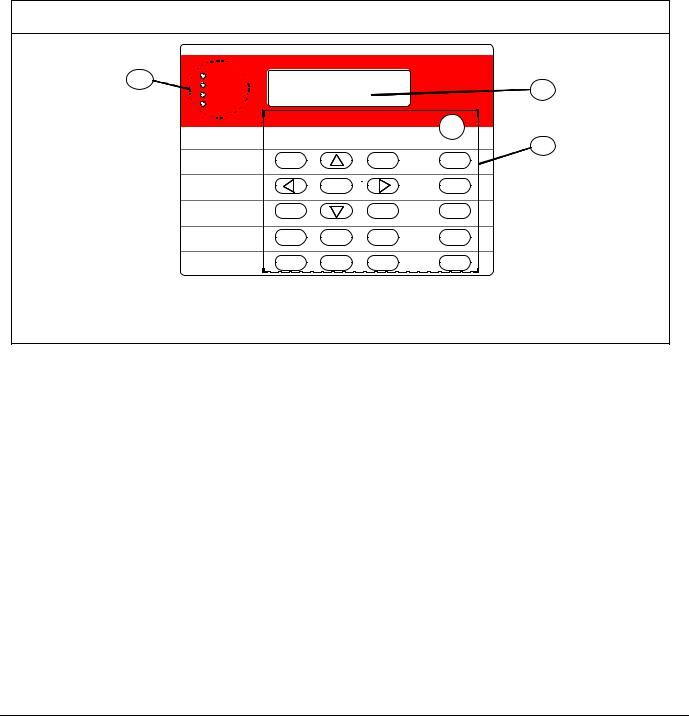
FPD-7024 | Operation and Installation Guide | |
3.0 |
System Operation |
|
|
|
3.3.2FMR-7033 Keypad
The FMR-7033 Keypad is an alphanumeric LCD keypad. Up to four of these keypads can be mounted apart from the main control panel to provide additional locations for system status and control. The LCD display and keys operate identically to those of the built-in keypad on the control panel (refer to Appendix A on page 85).
Figure 9: FMR-7033 Keypad
1 |
Alarm |
|
|
BOSCH |
|
Silenced |
|
|
2 |
|
Supervisory |
|
|
|
|
Trouble |
|
|
|
|
|
TEST WEEKLY |
|
|
|
|
|
|
Silence |
|
|
|
|
3 |
|
1 |
2 |
3 |
ACK |
|
4 |
5 |
6 |
Reset |
7 |
8 |
9 |
Drill |
Back* |
0 |
# |
Disable |
Prog |
Enter |
|
|
|
History |
|
Test |
1 -LEDs
2 –Keypad Display
3 -Keys
3.4Testing
Select any of seven special test modes using the [Test] key on the built-in and FMR-7033 keypads.
3.4.1Walk Test
The Walk Test allows a technician to alarm each point manually to ensure that detectors connected to a point send an Alarm report to the control panel. While in this mode, the LCD shows the system test status and the trouble sounder sounds every 10 sec. Outputs programmed for general alarm or fire alarm output, or outputs mapped to points using zones activate during this test as points are alarmed and restored:
When selecting this mode, three options are given for activation of outputs:
As each point is alarmed, the outputs activate once (if selected) and power is reset. As each point is activated, alarms and restorals are logged in the control panel’s history log. When the point returns to standby, the outputs activate twice. The control panel attempts to reset points ten times to restore them. Points remaining alarmed when exiting from the walk test mode cause an immediate alarm.
3.4.2Communicator Test
The communicator sends a test report. While communication is in progress, the Power LED flashes. When the communication succeeds, a long keypad beep sounds, the Power LED returns to normal, and the display returns to normal.
SHORT ACTIVE: |
1 second activation |
LONG ACTIVE: |
5 second activation |
NO ACTIVE: |
outputs do not activate |
Bosch Security Systems, Inc. | 9/08 | F01U008458-01
26

FPD-7024 | Operation and Installation Guide | |
3.0 |
System Operation |
|
|
|
This test is available only if your system sends alarms and system information to a monitoring service, and was programmed by the security installing company to permit communicator tests.
Terminating the communicator test function (with the [*/Back] key) resets the communicator and discards all unsent reports. When an off-normal condition occurs during a Communicator test, the test automatically resets, clearing all reports, so the off-normal conditions are sent normally.
3.4.3Call for Remote Programming
Phone Numbers 1 and 3 must be programmed, along with Account Code 1. The control panel calls Phone Number 3 and attempts to connect for downloading. If the control panel is already using the phone line, it sounds the three-beep error tone. This function requires an access code with programming authority (Level 1).
3.4.4Test Battery/NAC Circuits
If a power failure occurs, your control panel has a built-in battery that continues to power the system for several hours. The control panel automatically recharges the battery when power is restored. In this test mode, the system operates the local NAC circuits and tests the battery for two seconds. The test results are shown at the end of the test, and are not reported to the central station. Pressing the [*/Back] key or the [#/Enter] key returns the display to standby mode, or the unit times out after three minutes.
3.4.5Answer for Remote Programming
The control panel immediately seizes the phone line to answer a remote programming call. While programming is underway, the Trouble LED flashes. This also allows on-site PC downloading. If the control panel already uses the phone line for a report communication, it sounds the three-beep error tone. This function requires an access code with programming authority (Level 1).
3.4.6Manually Activate Outputs
This test turns a selected output on and off manually.
3.4.7Read Zone Input Levels
This test shows the status of a selected on-board point. The loop existing through the point is shown.
Normal loops show 11 to 15 mA. Loops in alarm show over 25 mA, and loops in trouble show less than 6 mA.
3.4.8Addressable Point Test (MUX Test)
This test allows activation of the special test mode for addressable (multiplex) devices. This applies only if the optional D7039 Addressable Point Bus Expander module is installed.
When this test mode is selected, the system asks which bus to test, 1 or 2. Select 1 to test points 9 to 128 and select 2 to test points 129 to 255. The system presents 5 options:
•List Devices: Shows the point numbers of all devices on the selected bus. Some devices (such as a dual point module) can use two or more points
•Show Holes: Lists locations on the bus that have no assigned device. This can help to find programming errors or identify an available address for a new device.
•Show Extras: The system scans the bus to identify devices that are present on the bus, but are not programmed into the system. Scanning the bus takes about 60 sec to scan the bus. Restoring the bus after scanning also takes about 60 sec. The system cannot identify devices above Address 128 on Bus 1, or below Address 129 on Bus 2. If you know that a device is connected to the system but cannot find it, ensure that it is connected to the correct bus: 9 to 128 for Bus 1, 129 to 255 for Bus 2.
•Show Missing: Lists devices programmed into the system but not present on the bus are listed. Unless a device was programmed into the system (such as using MUX EDIT), it is not considered missing.
•Show Status: After you select a device and press [#/Enter], this test shows detailed status information for the selected device. Eight conditions (not all status conditions apply to or are supported by all devices) are shown. See the display shown below (which updates automatically every five seconds). For this option, you can view the status of any MUX device regardless of which bus you selected to test when test mode was entered.
XxLxRxDxMxTxFxAx
Bosch Security Systems, Inc. | 9/08 | F01U008458-01 |
27 |

FPD-7024 | Operation and Installation Guide | |
3.0 |
System Operation |
|
|
|
x is either 0 or 1 depending on whether the condition is false or true (0=false and 1=true). The letters indicate the condition:
X:Reserved for future use.
L:Commanded relay state - this is how the output relay should be set.
R:Actual relay state - this is how the output relay is actually set.
D:Detector dirty - the detector is excessively sensitive.
M:Missing device - the device cannot be found on the loop. Unless a device was programmed into the system (such as using MUX EDIT), it is not considered missing.
T:Tamper – the detector’s case was opened.
F:Loop fault - the loop from a contact input device is open, or the device is faulted.
A:Loop alarm - the point is in alarm.
Pressing [*/Back] ends the display for any of these modes.
Examples: X0L0R0D0M0T0F0A0 (relay off, not dirty, not missing, no tamper, no fault and no alarm).
3.4.9Sensitivity Test
Tests the mux smoke detectors to determine if they are within their normal range of sensitivity. Press [Test] then [9].
3.5Point/Zone Mapping
The control panel supports a flexible system to map input points to output points. The system defaults so that all NAC outputs are activated by a fire alarm. By programming output zones, you can create almost any output activation scheme, such as “floor above and floor below” activation or conditional elevator recall.
Input points: Smoke detectors, pull stations, and so on.
Zone: A group of input points (Zones 1 to 50 are configurable, 52 to 63 are activated automatically).
Output points: NACs (notification appliance circuits) such as bells, strobes, and relays.
Inputs activate zones, and zones activate outputs.
Zones 1 to 50 are available for the installer to program. Each input can activate one zone; however, any number of inputs can be mapped to the same zone.
Zones above 50 are automatically activated by inputs. For example, any input that is configured as a waterflow type activates Zone 61 when it is alarmed. Any output driven by Zone 61 activates when any waterflow type point is alarmed.
Refer to Figure 10 to show how inputs control zones and zones control outputs.
Bosch Security Systems, Inc. | 9/08 | F01U008458-01
28
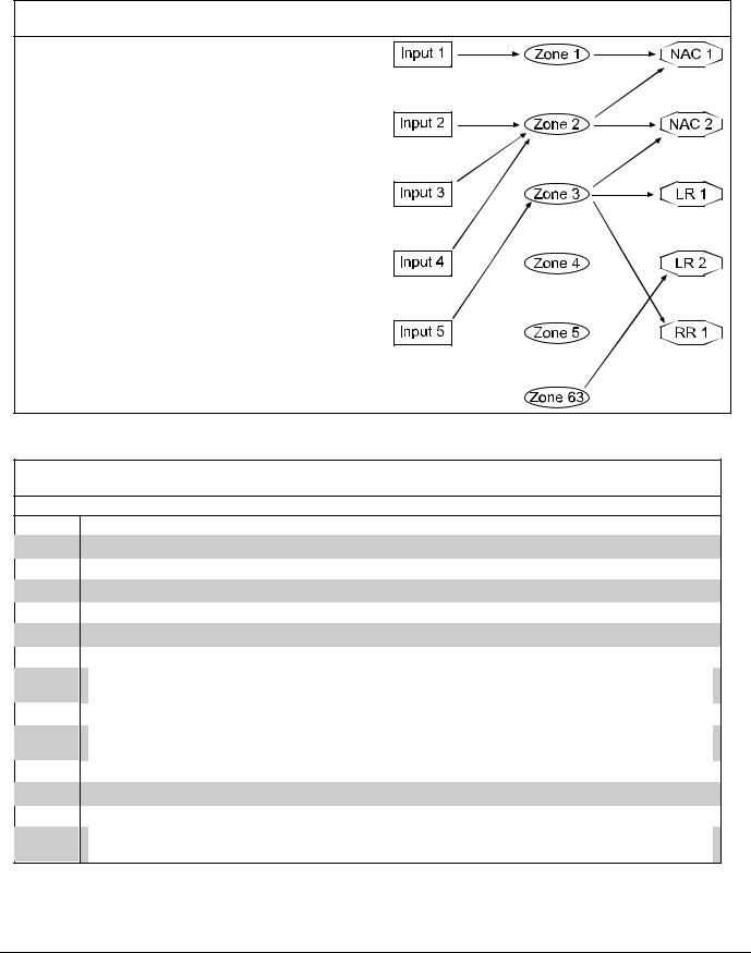
FPD-7024 | Operation and Installation Guide | |
3.0 |
System Operation |
|
|
|
Figure 10: Mapping, Inputs, Zones, and Outputs
Input Point 1 is assigned to Zone 1, mapped to NAC Point 1.
Input Point 2 is assigned to Zone 2, mapped to NACs 1 and 2.
Input Point 3 is assigned to Zone 2, mapped to NACs 1 and 2.
Input Point 4 is assigned to Zone 2, mapped to NACs 1 and 2.
Input Point 5 is assigned to Zone 3, mapped to NAC 2, LR 1 and RR 1.
LR: Local relay
RR: Remote relay
General Alarm Zone 63 drives LR 2.
Up to 64 zones can be assigned. The installer can assign Zones 1 to 50. Zones 51 to 63 are hard-coded to preassigned conditions. Refer to Table 13.
Table 13: Pre-Assigned Zones
|
|
Zone |
Pre-Assigned Condition |
51Reserved for future use.
52General Fire Alarm, Waterflow (non-silenceable). Same as Zone 53, but remains active even while system is silenced.
53General Fire Alarm (silenceable). Active when a fire alarm condition is present; does not activate for waterflow.
54Activates for approximately 7 sec before dialing, to initiate dial tone on a ground start phone system.
55General Supervisory (silenceable)
56General Waterflow (silenceable)
57Communication Trouble. Active when the dialer fails to communicate; remains active until communication through the digital communicator is restored.
58General Supervisory Alarm (non-silenceable). Active when any supervisory alarm condition is present.
59Alarm Verification. Active while alarm verification is in progress. This starts with the first detection of an alarm to be verified and clears in two minutes, or when system is reset.
60No AC. Active when AC power fails.
61General Waterflow (Non-silenceable). Active when any waterflow alarm is present.
62General Trouble. Active while any system trouble is present, not active in test and programming modes.
63General Alarm, Waterflow (non-silenceable). Active while any alarm, including supervisory, is present. Remains active even while system is silenced.
Bosch Security Systems, Inc. | 9/08 | F01U008458-01 |
29 |

FPD-7024 | Operation and Installation Guide | |
3.0 |
System Operation |
|
|
|
3.6Personal Identification Numbers
The personal identification number (PIN) is the four digit code users enter at the keypad to gain access to the system. A PIN can be assigned to each User Number. The User Number identifies each person using the system. There are 16 possible User Numbers (00 to 15). User codes 00 to 99 are available with the installation of a D7039 Multiple Expansion Module. The Authority Level assigned to each User Number determines which functions each user can perform.
Your system can have up to 100 different PINs, each four digits long. There is one PIN for each User Number. Attempting to assign the same PIN to multiple User Numbers results in the three-beep error tone, and the change is not made.
User Number 00 is designated as a Programmer’s Code. It can be used to silence alarms, reset, disable, and program the unit.
User Number 00 is shipped from the factory with the sequence of 9876. Change this code to one of your personal preference. It is automatically assigned the highest authority. Never program PINs with common sequences such as 1111, 1234, or 2468 because they are easily violated.
Authority levels are assigned to PINs to determine which functions each user can perform. Table 14 describes the four authority levels.
Table 14: PIN Authority Levels
|
|
|
|
PIN Authority Level |
Allowed Operations |
|
|
|
|
|
|
Maximum (1) |
|
All control panel operations, including programming, and disable |
|
|
|
|
|
Medium (2) |
|
System test modes, fire drill, reset, silence, view history |
|
|
|
|
|
Minimum (3) |
|
Silence, view history |
|
|
|
|
|
None (0) |
|
None |
|
|
|
|
|
Bosch Security Systems, Inc. | 9/08 | F01U008458-01
30
 Loading...