


 Loading...
Digital Congress Network - DCN
Security Systems
Installation and Operating Manual
en Digital Congress Network

en | i
DCN
Digital Congress Network
Bosch Security Systems B.V.
© 2003
All rights strictly reserved.
Reproduction by third parties in any form is strictly forbidden, unless prior written authorisation has been given. In the continuing quest for product improvement BOSCH reserves the right to change the specification of any article or system without prior notice.
Bosch Security Systems | 04-2003 | 3922 988 43318 en

en | ii
IMPORTANT SAFEGUARDS
Prior to installing or operating this product always read the Safety Instructions, which are available as a separate document.
Bosch Security Systems | 04-2003 | 3922 988 43318 en

en | iii
About this Manual
This manual is a comprehensive guide to the installation and operation of the Digital Congress Network System DCN. For portability and ease of use, this manual combines both installation details and a comprehensive section on individual and system operational procedures.
The manual is divided into the following chapters:
•Chapter 1. Introduction
Chapter 1 provides an introduction to the DCN system, as well as introducing the user to its System Philosophy based on the new technology recently introduced into congress systems.
•Chapter 2. to Chapter 9. Equipment Description.
Chapters 2 to 9 provide a comprehensive detailed description of all system units that combine to make up the DCN system.
•Chapter 10. Installation Techniques
Chapter 10 provides an introduction to the fundamentals of system design as well as a detailed description on how to install, configure and interconnect the DCN system units.
•Chapter 11. System Operation
Chapter 11 provides a comprehensive and detailed description on how to set-up and operate DCN’s main system items and its individual units.
•Chapter 12. Environmental Conditions and Maintenance
Chapter 12 gives the environmental conditions in which the DCN system should operate.
A section on maintenance is also included describing how to clean and store the DCN system units.
•Chapter 13. Technical data
Chapter 13 gives both the mechanical and electrical details of the DCN system.The mechanical section gives the dimensions of individual units.The electrical section gives the technical specification of the DCN system.
Microsoft® Windows® are registered trademarks of the Microsoft Corporation. IBM is a registered trademark. Pentium is a registered trademark of Intel Corporation.
Bosch Security Systems | 04-2003 | 3922 988 43318 en

en | iv
This page has been left blank intentionally
Bosch Security Systems | 04-2003 | 3922 988 43318 en

Digital Congress Network | Installation and Operating Manual | Table of Contents
Table of Contents
Chapter 1. |
Introduction Digital Congress Network (DCN) ............................ |
1-1 |
||
1.1 |
Contribution equipment .................................................................................. |
1-1 |
||
1.2 |
Central Control Equipment ............................................................................ |
1-1 |
||
1.3 |
Simultaneous Interpretation and Language Distribution Equipment .... |
1-2 |
||
1.4 |
Information display equipment ....................................................................... |
1-2 |
||
1.5 |
Application software packages ..................................................................... |
1-2 |
||
1.6 |
Installation equipment. ..................................................................................... |
1-3 |
||
1.7 |
Quick reference to DCN’s functions ............................................................ |
1-4 |
||
1.8 |
DCN Software packages ................................................................................ |
1-4 |
||
|
1 |
.8.1 |
Microphone Management software ....................................... |
1-4 |
|
1 |
.8.2 |
Synoptic Microphone Control ................................................ |
1-4 |
|
1 |
.8.3 |
Simultaneous Interpretation .................................................... |
1-4 |
|
1 |
.8.4 |
Language Distribution .............................................................. |
1-4 |
|
1 |
.8.5 |
Voting ............................................................................................ |
1-5 |
|
1 |
.8.6 |
Attendance Registration and Access Control .................... |
1-5 |
|
1 |
.8.7 |
Intercom ....................................................................................... |
1-5 |
|
1 |
.8.8 |
Text/Status Information Displays ............................................ |
1-5 |
|
1 |
.8.9 |
Automatic Camera Control ..................................................... |
1-5 |
|
1 |
.8.10 |
Delegate Database software .................................................. |
1-5 |
|
1 |
.8.11 |
ID-Card Encoder software ...................................................... |
1-5 |
|
1 |
.8.12 |
Message Distribution software ............................................... |
1-5 |
|
1 |
.8.13 |
System Installation software ................................................... |
1-5 |
|
1 |
.8.14 |
Video Display .............................................................................. |
1-5 |
|
1 |
.8.15 |
Multi-CCU Control .................................................................... |
1-5 |
|
1 |
.8.16 |
DCN Startup ............................................................................... |
1-6 |
|
1 |
.8.17 |
DCN Open Interface ................................................................. |
1-6 |
1.9 |
Glossary of Abbreviations and Acronyms ................................................... |
1-7 |
||
Chapter 2. |
Contribution Equipment .................................................................... |
2-1 |
||
2.1 |
CONTRIBUTION EQUIPMENT .................................................................... |
2-1 |
||
|
2.1.1 |
Table-top Contribution units .................................................... |
2-1 |
|
|
2.1.2 |
Delegate unit ............................................................................... |
2-2 |
|
|
2.1.3 |
Chairman unit ............................................................................. |
2-2 |
|
|
2.1.4 |
‘Microphone Only’ Function .................................................... |
2-2 |
|
|
2.1.5 |
Interpreter desk .......................................................................... |
2-2 |
|
2.2 |
LBB 3530/xx and LBB 3531/xx Delegate Discussion Unit .................... |
2-3 |
||
2.3 |
LBB 3533/xx and LBB 3534/xx Chairman Discussion Unit ................... |
2-3 |
||
|
2.3.1 |
Adjustment setting discussion units ...................................... |
2-4 |
|
|
2.3.2 |
Interconnection details discussion units .............................. |
2-5 |
|
|
2.3.3 |
Mounting discussion units (FIG. 2-6) ................................... |
2-5 |
|
2.4 |
LBB 3544/00, LBB 3545/00 and LBB 3546/00 |
|
||
|
Delegate conference units (Concentus) ..................................................... |
2-6 |
||
|
|
|
en | v |
2.5 |
LBB 3547/00 Chairman Conference Unit |
|
|
|
(Concentus) ....................................................................................................... |
2-7 |
|
|
2.5.1 |
Adjustment setting conference (Concentus) units ........... |
2-9 |
2.6 |
LBB 3549/00, LBB 3549/50 Pluggable Microphones ........................ |
2-10 |
|
2.7 |
LBB 3555/00 Intercom handset ............................................................... |
2-10 |
|
2.8 |
Flush-mounted Contribution equipment ................................................... |
2-11 |
|
2.9 |
LBB 3535/00 Dual Audio Interface unit ................................................. |
2-12 |
|
|
2.9.1 |
Flush Mounting Solutions ....................................................... |
2-13 |
2.10 |
LBB 3536/00, /10 Hand-microphones ................................................... |
2-15 |
|
2.11 |
LBB 3540/15 Multi-purpose connection unit ........................................ |
2-15 |
|
|
2.11.1 |
Flush Mounting Solutions ....................................................... |
2-17 |
2.12 |
LBB 3537/00, LBB 3537/50 Delegate microphone with |
|
|
|
control panel ................................................................................................... |
2-20 |
|
2.13 |
LBB 3537/10 Chairman microphone with control panel .................... |
2-21 |
|
2.14 |
LBB 3537/20 Pluggable Microphone control panel ............................ |
2-21 |
|
2.15 |
LBB 3538/00 FM Loudspeaker panel .................................................... |
2-22 |
|
2.16 |
LBB 3541/00 FM Delegate Voting Control panel ................................ |
2-22 |
|
2.17 |
LBB 3542/00, LBB 3542/20 FM Delegate/Chairman voting |
|
|
|
control panel with LC-display ...................................................................... |
2-23 |
|
2.18 |
LBB 3543/15 FM Chip-Card Reader ...................................................... |
2-24 |
|
2.19 |
LBB 4159/00 Set of 100 Chip Cards ..................................................... |
2-24 |
|
2.20 |
LBB 4157/00 Chip Card Encoder ............................................................ |
2-25 |
|
|
2.20.1 |
Position of the DIP switches ................................................ |
2-25 |
2.21 |
LBB 3524/00, LBB 3524/10 and LBB 3526/10FM Electronic |
|
|
|
channel selector panel .................................................................................. |
2-27 |
|
2.22 |
LBB 3525/00 Table top housing for Channel selector or |
|
|
|
Voting control panel ...................................................................................... |
2-29 |
|
2.23 |
LBB 3539/00 Blanking panels ................................................................. |
2-29 |
|
2.24 |
LBB 3527/00 Table top housing .............................................................. |
2-29 |
|
Chapter 3. |
Interpretation Equipment ................................................................. |
3-1 |
|
3.1 |
LBB 3520/10 Interpreter desk with back-lighting LC-display .............. |
3-1 |
|
|
3.1.1 Removal cable guide (Interpreter desk LBB 3520/10) ..... |
3-4 |
|
|
3.1.2 |
Installing Intercom Handset to LBB 3520/10...................... |
3-4 |
|
3.1.3 LBB 3513/00 Analog Audio Input/output Module ............. |
3-5 |
|
Chapter 4. |
Central Control Equipment .............................................................. |
4-1 |
|
4.1 |
Introduction Central control equipment ....................................................... |
4-1 |
|
4.2 |
LBB 3500/05, LBB 3500/05(D) Basic Central Control Unit ................ |
4-2 |
|
4.3 |
LBB 3500/15, LBB 3500/15(D) Central Control Unit ............................ |
4-2 |
|
4.4 |
LBB 3500/35, LBB 3500/35(D) Multi Central Control Unit .................. |
4-2 |
|
|
4.4.1 |
CCU Mains voltage and adjustment ..................................... |
4-5 |
|
4.4.2 |
CCU Mains cable, plug and socket ...................................... |
4-5 |
|
4.4.3 CCU Mains fuse rating ............................................................ |
4-5 |
|
Bosch Security Systems | 04-2003 | 3922 988 43318 en |
Table of Contents |

Digital Congress Network | Installation and Operating Manual | Table of Contents
4.5 |
CCU Trunk Communication Board (TCB4) ............................................... |
4-6 |
|
|
4.5.1 |
Installation ........................................................................................... |
4-6 |
|
4.5.2 |
S9 DIP-Switch settings .................................................................. |
4-7 |
|
4.5.3 |
Jumper settings .................................................................................. |
4-7 |
4.6 |
CU Protocol and Serial Port settings .......................................................... |
4-8 |
|
|
4.6.1 LBB 3500/05 Port 1 for Camera Control ................................... |
4-8 |
|
|
4.6.2 LBB 3500/15 and LBB 3500/35 (TCB 4)................................... |
4-8 |
|
4.7 |
Multi-CCU card ................................................................................................. |
4-9 |
|
|
4.7.1 |
Installation ............................................................................................ |
4-9 |
|
4.7.2 DIP-Switches S12 and S13 ............................................................ |
4-9 |
|
|
4.7.3 |
Jumper settings .................................................................................. |
4-9 |
|
4.7.4 |
LED indications .................................................................................. |
4-9 |
4.8 |
Connecting peripheral equipment to the CCU ........................................ |
4-11 |
|
4.9 |
CCU Audio Routing Modes ........................................................................ |
4-12 |
|
|
4.9.1 Audio Routing INSERTION mode .............................................. |
4-13 |
|
4.10 |
LBB 4106/00, LBB 4106/00D Extension power supply unit ............. |
4-14 |
|
4.11 |
LBB 3508/00 & LBB 3508/00D Audio Media Interface and |
|
|
|
Power Supply Unit ......................................................................................... |
4-15 |
|
4.12 |
19” Rack Mounting DCN Control Units .................................................... |
4-16 |
|
Chapter 5. |
DCN Control using Personal Computers ...................................... |
5-1 |
|
5.1 |
Minimum Software and hardware requirements ........................................ |
5-1 |
|
5.2 |
LBB 3510/00 PC Network card ................................................................. |
5-2 |
|
|
5.2.1 |
Installing PC-Network card ............................................................. |
5-3 |
|
5.2.2 Interconnections PC Network card ............................................... |
5-3 |
|
5.3 |
Windows and DCN Software modules ....................................................... |
5-3 |
|
5.4 |
LBB 3511/00 PC Card for Multi-CCU Systems ..................................... |
5-4 |
|
|
5.4.1 Installing PC-Card for Multi-CCU systems ................................. |
5-4 |
|
|
5.4.2 LBB 3511/00 DIP-switch S12 and S13 settings ....................... |
5-5 |
|
5.5 |
Connection PC to CCU .................................................................................. |
5-6 |
|
5.6 |
PC NETWORK SYSTEM ............................................................................... |
5-9 |
|
5.7 |
Software configuration Master CCU PC (OS/2) ....................................... |
5-9 |
|
5.8 |
Connecting Peripheral devices ................................................................... |
5-13 |
|
Chapter 6. |
DCN Camera Control .......................................................................... |
6-1 |
|
6.1 |
Allegiant Video Switcher ................................................................................. |
6-1 |
|
|
6.1.1 |
Allegiant Switcher Control Keyboards .................................. |
6-1 |
|
6.1.2 |
Cameras and Monitors ............................................................. |
6-1 |
|
6.1.3 |
INSTALLATION .......................................................................... |
6-2 |
|
6.1.4 |
Set-up Camera configuration .................................................. |
6-5 |
6.2 |
Direct Camera Control .................................................................................... |
6-6 |
|
|
6.2.1 |
Virtual Keyboard ......................................................................... |
6-6 |
|
6.2.2 |
Camera and Monitor ................................................................. |
6-6 |
|
6.2.3 |
Installation ................................................................................... |
6-6 |
|
6.2.4 |
Set-up Camera Configuraion .................................................. |
6-7 |
|
|
6.2.4.1Stand-alone DCN system .................................................... |
6-7 |
|
|
|
|
en | vi |
|
|
6.2.4.2DCN PC controlled system with single CCU ................. |
6-8 |
|
6.3 |
Switching options using a personal computer ........................................... |
6-8 |
||
Chapter 7. |
DCN Installation accessories .......................................................... |
7-1 |
||
7.1 |
Introduction Installation accessories ............................................................ |
7-1 |
||
|
7.1.1 |
LBB 4114/00 |
Trunk-cable splitter 7 ................................................. |
-2 |
|
7.1.2 |
LBB 4115/00 |
Tap-off Unit ............................................................... |
7-2 |
|
7.1.3 |
Cable assemblies and connectors ................................................ |
7-3 |
|
|
7.1.4 |
Connectors ......................................................................................... |
|
7-4 |
|
7.1.5 |
LBB 4117/00 |
Set of 25 cable locking clamps ........................... |
7-4 |
|
7.1.6 |
LBB 4118/00 |
Termination plug for DCN Cable ........................ |
7-4 |
Chapter 8. |
Information Displays ......................................................................... |
8-1 |
||
8.1 |
LBB 3512/00 Data Distribution Board ...................................................... |
8-1 |
||
|
8.1.1 |
Remote Switching Solutions ........................................................... |
8-3 |
|
|
8.1.2 |
Installing Data Distribution board LBB 3512/00. ....................... |
8-4 |
|
|
8.1.3 |
Connecting Hall Displays to the DCN System ........................... |
8-4 |
|
|
8.1.4 |
Interconnection for Video hall displays and Video |
|
|
|
|
Projectors ............................................................................................ |
|
8-5 |
Chapter 9. |
DCN Peripheral Equipment .............................................................. |
9-1 |
||
9.1 |
Introduction Peripheral Equipment ............................................................... |
9-1 |
||
|
9.1.1 |
Telos Digital Telephone Interface ................................................... |
9-1 |
|
Chapter 10. |
Installation Techniques ................................................................... |
10-1 |
||
10.1 |
Introduction Installation Techniques .......................................................... |
10-1 |
||
|
10.1.1 |
System design fundamentals ........................................................ |
10-1 |
|
10.2 |
Power Handling Capacity ............................................................................ |
10-2 |
||
10.3 |
Trunk outlets and Tap-offs ........................................................................... |
10-3 |
||
|
10.3.1 |
Tap-off limitations ............................................................................. |
10-3 |
|
|
10.3.2 |
Using Tap-Off unit LBB 4115/00 ................................................. |
10-5 |
|
|
10.3.3 |
Maximum cable lengths using Trunk-outlets |
|
|
|
|
and/or Tap-offs ................................................................................. |
10-5 |
|
10.4 |
Calculating the PCF of a System with respect to cable length .......... |
10-6 |
||
|
10.4.1 |
Calculating Step-by-Step .............................................................. |
10-6 |
|
|
10.4.2 |
Graph explanation ........................................................................... |
10-8 |
|
|
10.4.3 |
Graph reference examples ............................................................ |
10-9 |
|
10.5 |
Control Capacity .......................................................................................... |
|
10-10 |
|
10.6 |
Stand-alone Systems .................................................................................. |
|
10-10 |
|
|
10.6.1 |
Basic System (without extension units) ................................... |
10-10 |
|
|
10.6.2 |
System layout (without extension units) ................................... |
10-11 |
|
|
10.6.3 |
System with Extension units ........................................................ |
10-11 |
|
10.7 |
Computer Based Systems ........................................................................ |
10-12 |
||
|
10.7.1 |
PC Network System ...................................................................... |
10-14 |
|
10.8 |
Multi-CCU system ....................................................................................... |
|
10-15 |
|
|
10.8.1 |
Multi-CCU and PC interconnection .......................................... |
10-15 |
|
Bosch Security Systems | 04-2003 | 3922 988 43318 en |
Table of Contents |

Digital Congress Network | Installation and Operating Manual | Table of Contents
10.9 |
Remote Controller ....................................................................................... |
10-16 |
||
|
10.9.1 |
Installation ....................................................................................... |
10-16 |
|
|
10.9.2 |
Typical examples using the Remote Controller ...................... |
10-17 |
|
10.10 |
Interconnecting Interpretation Equipment ............................................. |
10-18 |
||
|
10.10.1 |
Interconnecting Interpreter desks .............................................. |
10-18 |
|
|
10.10.2 Interconnection between booths ............................................... |
10-18 |
||
10.11 |
Language Distribution Equipment ........................................................... |
10-19 |
||
|
10.11.1 |
Introduction ..................................................................................... |
10-19 |
|
|
10.11.2 |
Installation ....................................................................................... |
10-20 |
|
Chapter 11. System Set-up & Operation .......................................................... |
11-1 |
|||
11.1 |
Introduction ...................................................................................................... |
11-1 |
||
|
11 |
.1.1 |
Initializing a stand-alone system .................................................... |
11-1 |
|
11 |
.1.2 |
Initializing a PC-based system ...................................................... |
11-1 |
11.2 |
Setting up a stand-alone system ................................................................. |
11-2 |
||
|
11 |
.2.1 |
System mode selection (Multi-CCU only) ................................. |
11-2 |
|
11 |
.2.2 |
Microphone control modes ............................................................ |
11-2 |
11.3 |
Multi-CCU Set-up for the first-time. ............................................................ |
11-3 |
||
|
11 |
.3.1 |
Downloading Control PC-software ............................................. |
11-3 |
11.4 |
Maintenance Menu ......................................................................................... |
11-3 |
||
|
11 |
.4.1 |
To set system default LANGUAGE ............................................. |
11-4 |
|
11 |
.4.2 |
To set system INTERCOM OPERATOR POSITION ............. |
11-4 |
11.5 |
Sound Management ....................................................................................... |
11-5 |
||
|
11 |
.5.1 |
Equalizer function ............................................................................ |
11-5 |
|
11 |
.5.2 |
Loudspeakers ................................................................................... |
11-5 |
11.6 |
Additional stand-alone operations (applicable to conference |
|
||
|
units only) ......................................................................................................... |
11-6 |
||
|
11 |
.6.1 |
Voting modes .................................................................................... |
11-6 |
|
11 |
.6.2 |
Intercom Facilities ............................................................................ |
11-6 |
11.7 |
Delegate/Chairman unit operation (Conference units only) ................. |
11-7 |
||
|
11 |
.7.1 |
Introduction ....................................................................................... |
11-7 |
|
11 |
.7.2 |
OPERATION Delegate Units LBB 3544/00, |
|
|
|
|
LBB 3545/00, LBB 3546/00 ...................................................... |
11-8 |
|
11 |
.7.3 |
OPERATION Chairman Unit LBB 3547/00 ........................... |
11-11 |
11.8 |
Operating Delegate/Chairman units (Discussion units only) ............ |
11-14 |
||
|
11 |
.8.1 |
Microphone ..................................................................................... |
11-14 |
|
11 |
.8.2 |
Priority function ( LBB 3533/xx and |
|
|
|
|
LBB 3534/xx only) ........................................................................ |
11-14 |
|
11 |
.8.3 |
Language channel selection (LBB 3531/.. |
|
|
|
|
and LBB 3534/.. only) .................................................................. |
11-14 |
11.9 |
Interpretation ................................................................................................. |
11-15 |
||
|
11 |
.9.1 |
Incoming channel control (LISTENING) .................................. |
11-15 |
|
11 |
.9.2 |
Outgoing channel control (SPEAKING) .................................. |
11-15 |
|
11 |
.9.3 |
Microphone (Micro) ...................................................................... |
11-15 |
|
11 |
.9.4 |
Microphone locks .......................................................................... |
11-15 |
|
11 |
.9.5 |
‘Override’ ......................................................................................... |
11-15 |
|
11 |
.9.6 |
Relay Interpretation with auto-relay 11-15 |
|
11.10 |
Operating the Interpreter Desk 11-17 |
|
||
|
|
|
en | vii |
|
11.10.1 Incoming Channel Selection ....................................................... |
11-17 |
|
|
11.10.2 Assigning Pre-select keys ............................................................ |
11-17 |
|
|
11.10.3 Incoming Floor switch and Auto-relay ....................................... |
11-17 |
|
|
11.10.4 Language Quality Indication ........................................................ |
11-17 |
|
|
11.10.5 Interpreter desk Listening ............................................................ |
11-18 |
|
|
11.10.6 Outgoing Channel Selection ...................................................... |
11-18 |
|
|
11.10.7 Typical Displays showing outgoing channels .......................... |
11-19 |
|
11.11 |
Programming the Interpreter desk ........................................................... |
11-20 |
|
|
11.11.1 |
Programming the Interpreter desk ............................................ |
11-20 |
|
11.11.2 Entering the desks programming mode ................................... |
11-21 |
|
|
11.11.3 Menu Programming procedures ................................................. |
11-21 |
|
Chapter 12. Environmental Conditions and Maintenance ........................... |
12-1 |
||
12.1 |
System |
.............................................................................................................. |
12-1 |
12.2 |
Public areas ..................................................................................................... |
12-1 |
|
|
12.2.1 |
Lighting .............................................................................................. |
12-1 |
|
12.2.2 |
Public displays (placement/viewing distance) .......................... |
12-1 |
|
12.2.3 ............................................................................... |
Public walkways |
12-1 |
|
12.2.4 ........................................ |
Headphones with interpreter systems |
12-1 |
|
12.2.5 .............................................. |
Recommended speaking distance |
12-1 |
12.3 |
Technical .............................................................................................rooms |
12-1 |
|
12.4 |
Interpreter ..........................................................................................booths |
12-2 |
|
12.5 |
Ventilation ........................................................................................................ |
12-2 |
|
12.6 |
Cleaning ........................................................................................................... |
12-2 |
|
12.7 |
Storage ............................................................................................................. |
|
12-2 |
Chapter 13. |
Technical ...................................................................................Data |
13-1 |
|
13.1 |
Mechanical .............................................................................................data |
13-1 |
|
|
13.1.1 ............................................ |
LBB 3500/.. Central Control Units |
13-1 |
|
13.1.2 |
Mounting brackets |
(in- |
|
|
cluded with type No.s LBB 3500/xx, |
|
|
............................................................ |
LBB 4106/00, LBB 3508) |
13-1 |
|
13.1.3 |
LBB 4106/00 and LBB 4106/00 (D) |
|
|
........................................................ |
Extension Power Supply Unit |
13-2 |
|
13.1.4 |
LBB 3508/00 and LBB 3508 (D) |
|
|
............................................................ |
Audio Media Interface Unit |
13-2 |
13.2 |
Table-top ................................................................................................units |
13-2 |
|
|
13.2.1 ............................................................................. |
Conference Units |
13-2 |
|
13.2.2 .............................................................................. |
Discussion Units |
13-2 |
|
13.2.3 .................................. |
LBB 3535/00 Dual Audio Interface Unit |
13-2 |
|
13.2.4 ............................................... |
LBB 3536/xx Hand microphones |
13-3 |
|
13.2.5 ................................................ |
LBB 3555/00 Intercom handset |
13-3 |
|
13.2.6 ................................ |
LBB 3525/00 Channel Selector housing |
13-3 |
|
13.2.7 |
LBB 3527/00 Table - top housing for FM loudspeaker |
|
|
................................................................................................... |
panel |
13-3 |
13.3 |
Flush Mounted ...........................................................................Equipment |
13-4 |
|
|
13.3.1 |
LBB 3524/00 and LBB 3424/10 FM Electronic |
|
|
................................................................. |
Channel Selector Panel |
13-4 |
Bosch Security Systems | 04-2003 | 3922 988 43318 en |
Table of Contents |

Digital Congress Network | Installation |
and Operating Manual | Table of Contents |
|||
|
|
|
|
|
|
13.3.2 |
LBB 3526/10 |
FM Electronic Channel Selector Panel |
... 13-4 |
|
13.3.3 |
LBB 3537/00 and LBB 3537/50 Microphone with |
|
|
|
|
FM Control Panel ..................................................................... |
13-5 |
|
|
13.3.4 |
LBB 3537/10 |
FM Chairman Priority Control Panel ........ |
13-5 |
|
13.3.5 |
LBB 3539/00 Blank panel ................................................... |
13-5 |
|
|
13.3.6 |
LBB 3537/20 and LBB 3537/50 FM Microphone |
|
|
|
|
Control Panel for microphones LBB 3549/00 and |
|
|
|
|
LBB 3549/50 |
........................................................................... |
13-6 |
|
13.3.7 |
LBB 3538/00 FM Loudspeaker panel .............................. |
13-6 |
|
|
13.3.8 |
LBB 3540/15 |
Multi-purpose Connection Unit ................ |
13-7 |
|
13.3.9 |
LBB 3541/00 |
Delegate Voting Control Panel ................. |
13-7 |
|
13.3.10 LBB 3542/00 FM Delegate/Chairman Voting Control |
|
||
|
|
Panel with LC-display ............................................................. |
13-7 |
|
|
13.3.11 LBB 3543/15 Chip Card Reader ....................................... |
13-8 |
||
13.4 |
Installation Accessories |
................................................................................ |
13-8 |
|
|
13.4.1 |
LBB 4114/00 Trunk Cable Splitter LBB 4115/00 |
|
|
|
|
Tap-off Unit ................................................................................ |
|
13-8 |
13.5 |
Electrical data .................................................................................................. |
|
13-9 |
|
|
13.5.1 |
Microphones (General) .......................................................... |
13-9 |
|
|
13.5.2 |
Headphones ............................................................................. |
|
13-9 |
|
13.5.3 |
Transmission links .................................................................... |
13-9 |
|
|
13.5.4 |
Combined units ...................................................................... |
13-10 |
|
|
13.5.5 |
System Electrical and Electro-acoustical |
|
|
|
|
characteristics |
........................................................................ |
13-10 |
|
13.5.6 |
System environmental conditions ...................................... |
13-10 |
|
|
13.5.7 |
Interface data .......................................................................... |
|
13-10 |
|
13.5.8 |
Mains supply ........................................................................... |
|
13-10 |
|
13.5.9 |
Power consumption (nominal) ............................................ |
13-10 |
|
13.6 |
System limitations ........................................................................................ |
|
13-11 |
|
13.7 |
Connection details ...................................................................................... |
|
13-11 |
|
|
13.7.1 |
Mains cable ............................................................................. |
|
13-11 |
|
13.7.2 |
DCN circular connectors ..................................................... |
13-11 |
|
|
13.7.3 |
Cable connection ................................................................. |
13-11 |
|
|
13.7.4 |
Pluggable microphones LBB 3549/xx ............................ |
13-11 |
|
|
13.7.5 |
CONCENTUS units .............................................................. |
13-12 |
|
|
13.7.6 |
CONCENTUS units .............................................................. |
13-12 |
|
|
13.7.7 |
Cable connection ................................................................... |
13-12 |
|
|
13.7.8 |
Jack-plug .................................................................................. |
|
13-12 |
|
13.7.9 |
Interpreter desk (headset socket DIN-type) .................... |
13-12 |
|
|
13.7.10 |
15-pole D-type connector PC Interface ........................... |
13-12 |
|
13.8 Available Audio Down Link Channels 13-13 |
|
|||
|
13.8.1 |
Stand-alone systems ............................................................. |
13-13 |
|
|
13.8.2 |
Systems with a PC ................................................................ |
13-13 |
|
13.9 TEMPLATE FOR TABLE CUT-OUT OF CONCENTUS UNITS ...... |
13-14 |
|||
Bosch Security Systems | 04-2003 | 3922 988 43318 en
en | viii
Table of Contents
Digital Congress Network | Installation and Operating Manual | Chapter 1 - Introduction to DCN |
en | 1-1 |
|
|
Chapter 1. Introduction Digital Congress Network (DCN)
The BOSCH Digital Network System (DCN) provides flexible control facilities for all types of conferences from small discussion groups to international, multi-lingual congresses with hundreds of delegates. Facilities range from basic microphone management, to delegate identification and registration, electronic voting, information distribution and display, up to extensive simultaneous interpretations and automatic camera control. A single operator using a computer with DCN’s application software can control even the largest of congresses. Systems can be expanded by adding more contribution equipment and introducing PC control with DCN’s application software.
The full range of DCN equipment includes:
1.Contribution equipment
2.Central control equipment
3.Simultaneous interpretation and language distribution equipment
4.Information display equipment
5.Application software packages
6.Installation equipment
DCN equipment is also complemented by external equipment such as video and character displays, TV cameras, personal computers, monitors, PA amplifiers, loudspeakers and printers all of which are fully compatible and easily integrated into the DCN system.
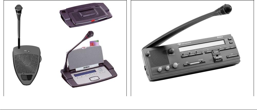
1.1Contribution equipment
Contribution equipment describes the units which participants use to contribute to a conference. Depending on the type of contribution unit, delegates can access the DCN’s wide range of facilities to listen, speak, register a request-to-speak, receive screen messages, communicate with other delegates via an intercom and to participate in electronic voting sessions. On insertion of an ID-card dedicated software is required giving much more facilities.
Contribution units can be used free-standing on a table-top, or flush-mounted in desks, seat backs or armrests. Other microphone types such as lavalier and hand-held are also available, allowing contribution from non seated participants such as a guest speaker for example.
1.2Central Control Equipment
The Central Control Unit (CCU) forms the heart of the DCN system.The CCU can operate standalone to provide automatic conference control, or it can be accessed by an operator via a personal computer (PC) when more extensive management control is required.
All CCU’s can control up to 240 contribution units. If more capacity is required, slave CCU’s can be connected, each of which increases the system capacity by 240 contribution units. A maximum of 16 slave CCU’s can be connected to a system. Other extension units include an Extension Power Supply unit and an Audio Media Interface unit which extend the systems power handling capacity.
The CCU offers basic microphone management, simultaneous interpretation and electronic voting facilities, as well as digital audio channels, data channels and communication channels.This allows effective unsupervised control of even large or international conferences. The extended CCU offers all the facilities of the basic CCU, but allows operator control via a personal computer (PC).The operator can access the wide range of DCN application software packages, each with a specific function in controlling and monitoring conferences.This includes advanced simultaneous interpretation and microphone management, message generation and display, voting procedures, intercom, creating a delegate data base, attendance registration, audio processing and automatic camera control.
Bosch Security Systems | 04-2003 | 3922 988 43318 en |
Contribution equipment |

Digital Congress Network | Installation and Operating Manual | Chapter 1 - Introduction to DCN |
en | 1-2 |
|
|
1.3Simultaneous Interpretation and Language Distribution Equipment
Interpretation.
Using the same trunk-line cabling DCN’s interpreter desks can easily be integrated into existing systems, offering comprehensive facilities for simultaneous interpretation.The desk can accommodate up to 15 different language channels, plus the original floor language. A maximum of six desks can be installed per interpreter booth.They can be used stand-alone or as part of a more comprehensive system.When used stand-alone, the units built-in microprocessor is manually programmed to allocate language channels, channel routing and interlocks. In PC operator-controlled systems, the desk is used in combination with DCN dedicated software, and other interpreter desks (if required) to form a completely integrated interpretation network. An in-built facility enables direct or auto-relay interpretation to cater for less well known languages. Each desk has two output channels, one for the normal interpretation and one for second or auto-relay translation.
Language Distribution
Distribution of languages to individual delegates can be by wired or wireless language distribution systems. A wired language distribution system uses delegate contribution units that include a language channel selector, or dedicated language channel selector units. A wireless language distribution system uses the Infra-red transmission technique.
1.4Information display equipment
The DCN system can distribute information to conference participants quickly and efficiently to suit all requirements. A wide range of displays are supported from simple LCD personal screens to video equipment for venue broadcasting.
The chairman unit, interpreter desk and one type of the delegate unit is equipped with a graphic (chairman, delegate) or alphanumeric (interpreter) LC-display which displays delegate information, voting results and operational procedures, public and personal messages, microphone status and multi-lingual user instructions.
Hall displays can quickly display conference information to a large number of conference participants. Numeric, alphanumeric or geographical displays are available, to display voting results. TV receivers and Video Displays allow high quality display of any live or recorded material, computer-generated graphics, text, and information generated by DCN software.
1.5Application software packages
A comprehensive range of software packages is available for use with centrally controlled PC-systems. These packages run under Microsoft® Windows® integrate conference preparation management and control into this versatile graphical computer environment. Any combination of packages can be down-loaded according to specific system requirements. DCN software packages are generally used in larger scale systems where operator control is required.
The PC running the software is connected to the DCN system and therefore has direct communication links with contribution, interpretation and control equipment via the systems trunkline data bus or the CCU’s serial communication port.Therefore all aspects of conference management can be brought to a single point of control, Leading to increased ease of use, efficiency and data distribution.
The range of DCN software packages includes:
•Microphone management
•Synoptic Microphone control
•System installation
•Parliamentary voting
•Multivoting
•Delegate Database
•Simultaneous Interpretation
•Text/Status Display
•Attendance Registration
•ID-Card Encoding
•Message Distribution
•Intercom
•Video Display
•Automatic Camera Control
•DCN Start-up
•Multi-CCU
•DCN Open Interface
BOSCH Security Systems | 04-2003 | 3922 988 43318 en |
Simultaneous Interpretation and Language Distribution Equipment |

Digital Congress Network | Installation and Operating Manual | Chapter 1 - Introduction to DCN |
en | 1-3 |
|
|
1.6Installation equipment.
Fast cost-saving installation is an important benefit of the DCN’s digital technology. A thin twin-coaxial cable carries all the system’s digital signals, eliminating the need for the costly and vulnerable multicore cables used in conventional analogue installations.The same cable is used to transport the signals to all delegates’ microphone units throughout the system and can be ‘tapped off ’ at any desired point to connect the microphone units or any system unit associated with the DCN system. Later capacity extensions - for example to add extra microphone units does not demand changes to the system cabling. All that is needed is to connect the required DCN system units or branches to the installed cabling.Trunk-line splitters and extension cable assemblies are available to simplify installations in difficult working areas.
DCN’s System Philosophy.
The DCN introduces the latest digital technology, bringing far reaching benefits to the audio quality, as well as to promote the addition of a wide range of external peripheral equipment to conference systems.
FIG 1-1 shows the concept of DCN’s digital communication techniques.The Network cabling forms the system infrastructure providing the communication media between the Microprocessor controlled Central Control and all units connected to it. Using standard plugs and connectors throughout the system means that units can be connected to the Network at any convenient points, making installation quick and simple.
Communication through the Network cabling and all units connected to it, is done using three dedicated digital communication IC’s, ACN 1, ACN 2 and ACN 3. Units that include an ACN 1 microprocessor - such as the delegate unit, chairman unit and interpreter desk - communicate to the Central Control Unit, via the units ACN 2 microprocessor on a send and receive basis (active or passive). Units that include an ACN 3 microprocessor - such as the Channel selector units - receive information on a receive basis only, such units are known as passive units.
Praedic
The integrated circuit (IC), PRAEDIC (Professional Audio Encoder Decoder Integrated Circuit) combines a built-in amplifier with both Analogue-to-Digital and Digital-to-Analogue convertors.The IC converts analogue signals (such as from a delegates’ microphone) and digitizes them for distribution throughout the DCN network cabling. In return the digitize signal is then fed back to the Praedic and converted back to an analogue signal for distribution throughout the DCN units - such as delegate loudspeakers and headphones.
PC-bus
PRAEDIC |
ACN 1 |
DCN Discussion Delegate/Chairman/Interpreter (contribution & distribution)
DAC |
ACN 3 |
cabling |
|
Network |
|||
Channel selector unit |
|||
(language distribution) |
|
||
ACN 1 - up/down
ACN 2 - up/down
ACN 3 - down only
ACN 1 |
PRAEDIC |
LBB 3510/00
Network card
ACN 1 |
PRAEDIC |
ACN 3 |
DAC |
Delegate/Chairman unit (Concentus)
e.g Hall Display
ACN 1 |
µProc. |
LBB 3512/00
Data Distribution Board
ACN 1 |
ACN 2 |
µProc. |
FLASH |
RAM |
DSP |
|
EPROM |
||||
|
|
|
PRAEDIC |
CONTROL |
PANEL |
PERSONAL
COMPUTER
Alternative for PC with LBB 3510/00 Network card
Central Control Unit (CCU)
FIG 1-1 DCN’s digital communication technique
Bosch Security Systems | 04-2003 | 3922 988 43318 en |
Installation equipment. |

Digital Congress Network | Installation and Operating Manual | Chapter 1 - Introduction to DCN |
en | 1-4 |
|
|
1.7Quick reference to DCN’s functions
Stand-alone System
A discussion system; delegates control their own microphone actions - without the need of a nonparticipating operator. Discussion systems cater for smaller groups, although the number of delegates can be extended to the total capacity of the DCN system. A discussion system therefore is ideal for small meeting halls, boardrooms, and hotels etc. where clear and concise speech intelligibility through sound amplification is required.
PC Controlled System
Delegates’ microphone actions are controlled by a none participating operator using a personal computer.
Microphone Management
Method by which delegates/operator control the microphone units. Microphone Management control therefore is needed in order to conduct civilised and disciplined discussions/conferences.
The DCN system has its own built-in standard microphone control functions.These functions are usually sufficient for use in discussion groups using a stand-alone system. In conference systems however a central PC operator has extended microphone management capabilities when using DCN’s dedicated microphone management software.
Microphone Management Operation Modes:
OPEN (AUTO)
The OPEN mode allows up to 1, 2 or 4 delegates (Active Micros) to control the on/off state of their own microphones unit simultaneously without the use of operator intervention.When more than the number of Active Micros has been reached, delegates requesting to speak join a request- to-speak list.
OVERRIDE (First-In-First-Out)
The Override mode allows up to 1, 2 or 4 delegates to speak on a FIRST-IN FIRST-OUT basis i.e Override.With the override mode, their is no request-to-speak list, only the pre-selected number of Active Micro’s may be switched on simultaneously.This means that if another delegate should switch on his microphone unit, the microphone of the first delegate having joined the group will be switched off, allowing the latest delegate to join in the discussion.
VOICE ACTIVATION
The ‘Voice’ activation mode is an automatic method for activating the microphones of the delegate and chairman units by voice.The maximum number of voice activated units available for selection in a stand-alone system is 2 or 4.This mode of operation is intended for free discussion amongst participating delegates. For enhanced operation an additional Public Address system is highly recommended.
1.8DCN Software packages
1.8.1 Microphone Management software
Microphone management software provides a text-based solution (delegates’ names) for managing delegates’ microphones. Run under Windows® the operator controls the delegates’ microphone operations through menus.
The Microphone Management software offers five modes of microphone control:
•Operator with *Request-to-speak list (MANUAL)
•Operator with *Request and **Response list
•Delegate with *Request-to-speak list (OPEN)
•Delegate control with override (of other delegates’ microphones)
*A Request-to-speak list is a list of delegates waiting to speak.To join the list delegates first press their microphone keys. If the maximum number of delegates are already speaking the delegates then joins the list. The number of delegates allowed to speak at the same time is set to 1,2,3, or 4.
**A response list is a list of delegates that need to react immediately to a current speaker. Response requests are positioned at the top of the request list.
•Delegate with Voice activation
REFERENCE: For more information refer to the LBB 3570 software manual
1.8.2 Synoptic Microphone Control
Synoptic microphone control software provides a graphical solution using pictograms of microphone units. Run under Windows® the operator controls microphone units by simply pointing and clicking a mouse on the desired unit. Synoptic microphone control is icon based. It relies on the location of seats and uses pictograms that show icons with seat numbers or with names.
REFERENCE: For more information refer to the LBB 3571 software manual
1.8.3 Simultaneous Interpretation
Interpretation is the term used where the language of the floor speaker is interpreted by interpreters using interpreter desks into the languages of the other conference participants.
REFERENCE: For more information refer to the LBB 3572 software manual
BOSCH Security Systems | 04-2003 | 3922 988 43318 en |
Quick reference to DCN’s functions |

Digital Congress Network | Installation and Operating Manual | Chapter 1 - Introduction to DCN |
en | 1-5 |
|
|
1.8.4 Language Distribution
Language distribution describes the means by which delegates listen to the floor speaker in the language of their choice. Interpretations can be forwarded to delegates headphones using units with either a built-in language channel selector or via an infra-red receiver.
1.8.5 Voting
Parliamentary voting
Parliamentary voting allows delegates to vote ‘NO’,‘ABSTAIN’ or ‘YES’. It provides facilities for vote registration and display, with a choice of ‘OPEN’ (non-secret) and ‘CLOSED’ (secret) voting modes and selectable interim voting functions. Up to 9999 voting motions can be prepared in advance in a single script file and recalled instantly during a voting session (available with PC systems only). In PC based systems, editing facilities are also provided to simplify the preparation of updating script files. REFERENCE: For more information refer to the LBB 3575 software manual
Display facilities for video signals and graphic information such as seating plans and statistical voting representations can also be added to the system, using hall displays such as projection or direct view TV receivers, or giant-screen VidiWalls for larger audiences. Personal video displays can also be added in the form of LCD TV displays.
REFERENCE: For more information refer to the LBB 3583 software manual
1.8.9 Automatic Camera Control
Automatic camera control allows the speaker to be displayed on one or more video displays connected to a video control switcher. One or more dome cameras’ with a fast moving pan and tilt, zoom lens and a large number of pre set positions are automatically activated by the microphone control signals of the contribution units.
REFERENCE: For more information refer to the LBB 3588 software manual
1.8.10 Delegate Database software
Multi voting
Multi-voting software allows up to 6 voting methods to be selected,‘Parliamentary, ‘Audience response’, ‘Multiple choice’, Opinion poll, Rating and For/against. Vote related parameters can be specified for each individual voting method, such as: vote type, result display type, interim display, screen and print legends, hall display, vote weighting, roll call, voting LEDs and abstain options.The user is able to print the final result and automatically export it to an MS-DOS file.
For more information refer to the LBB 3576 software manual. REFERENCE: For more information refer to the LBB 3576 software manual
1.8.6 Attendance Registration and Access Control
To register delegates to the DCN system, personnel ID-cards can be programmed and allocated to participating delegates.The card ensures that only authorised delegates are able to access the functions of a microphone unit, participate in a voting session and to make an intercom call.This facility is only applicable to units fitted with an ID chip card reader.
REFERENCE: For more information refer to the LBB 3578 software manual
1.8.7 Intercom
An intercom handsets allows two-way vocal communication between conference participants, interpreters and operator.
REFERENCE: For more information refer to the LBB 3573 software manual
1.8.8 Text/Status Information Displays
Information displays range from hall displays for rooms of all sizes, down to personal displays for individual delegates.
Most of the displayed information is in the form of alphanumeric messages, shown on microphone units equipped with LC-displays, as well as on hall displays. A choice of solutions are available for hall display information like voting motions and results, delegates’ names and affiliations, request-to speak lists, personal messages, public announcements and multiple choice questions.
Delegate Database software is used to create names files of conference participants. It is used by several other DCN software modules to identify the conference participant and to control the delegates access to DCN functionality, i.e. microphone control, voting, use of intercom facilities. REFERENCE: For more information refer to the LBB 3580 software manual.
1.8.11 ID-Card Encoder software
ID-Card Encoder Software enables encoding of a unique ID-card number to allow identification of each delegate when using DCN contribution units with an ID-card reader.
REFERENCE: For more information refer to the LBB 3580 software manual.
1.8.12 Message Distribution software
Message Distribution Software enables an operator to send individual or group messages to conference participants such as delegates and interpreters and to display text messages on hall displays.
REFERENCE: For more information refer to the LBB 3582 software manual.
1.8.13 System Installation software
System Installation is used to configure the DCN system. It allows linking of contribution units and users and assigning functions to audio channels. An installation file is required for DCN operation with PC control.
REFERENCE: For more information refer to the LBB 3585 software manual.
1.8.14 Video Display
Video Display software enables sending of relevant information for large screen video/data display or personal video/data display via a Video Client application.
REFERENCE: For more information refer to the LBB 3584 software manual.
Bosch Security Systems | 04-2003 | 3922 988 43318 en |
DCN Software packages |

Digital Congress Network | Installation and Operating Manual | Chapter 1 - Introduction to DCN |
en | 1-6 |
|
|
1.8.15 Multi-CCU Control
Multi-CCU Control software allows to use up to 16 CCU’s in a DCN system for a max. of 3840 contribution units. (Note: DCN’s Delegate Database software LBB 3580 supports names files with up to 1500 names).The Multi-CCU Control software is installed on a Master CCU PC operating under OS/2. It allows assignment of the CCU acting as "Audiomaster" and the CCU used for connection of interpreter desks.
REFERENCE: For more information refer to the LBB 3586 software manual.
1.8.16 DCN Startup
DCN Startup software is the basic software module for installation of all DCN software modules.The Startup screen shows the icons of all installed software modules that can be activated. It also can show the system configuration, defines auto-start options, takes care for error logging and allows the operator to control the master volume level and to listen to interpretations via a headphone. REFERENCE: For more information refer to the LBB 3590 software manual.
1.8.17 DCN Open Interface
The DCN open interface software allows remote control of a selected DCN functions via third party equipment. Control data exchange between DCN and the remote control device or system is done via a RS-232 port on the CCU. Access to the CCU is opened with the Open Interface software via a PC connection to the serial port of the CCU.
REFERENCE: For more information refer to the documentation on the disk of this module.
BOSCH Security Systems | 04-2003 | 3922 988 43318 en |
DCN Software packages |

Digital Congress Network | Installation and Operating Manual | Chapter 1 - Introduction to DCN en | 1-7
1.9 |
Glossary of Abbreviations and Acronyms |
|
|
|
|
|
P |
|
|||
|
|
|
|
PC |
Personal Computer |
A |
|
|
|
PCF |
Power Consumption Factor |
ACN-1, ACN-2, ACN-3 |
Integrated Circuit (IC) |
|
PCF value |
The value assigned to a specific unit or system |
|
Active unit |
Sends data on the up link and receives data on the down link |
|
PRAEDIC |
Professional Audio Encoder Decoder IC. |
|
Allow cancel request |
A pre-programmed system interlock, allowing the delegate to cancel a |
|
Passive Unit |
DCN unit that Receives data on the down link only |
|
|
|
request-to-speak |
|
|
|
Allow mic. off facility |
A pre-programmed system interlock, allowing delegates to switch off |
|
|
|
|
|
R |
|
|||
|
|
their microphone units without consent |
|
Rack-mounted |
Defines units that are capable of being mounted in a 19-inch cabinet |
|
|
|
|
Request accepted |
Displayed on a delegate unit informing the delegate the delegate that |
C |
|
|
|||
CCU |
|
Central Control Unit |
|
|
his request-to-speak has been accepted |
Chairman |
One who presides over or heads a meeting or conference |
|
Request |
Initiated by a delegate requesting to speak |
|
Contribution |
Participation within a meeting or conference using contribution units |
|
Request cancelled |
Displayed on delegate units informing the delegate that his request-to- |
|
Central Operator |
One who controls and organises a meeting or conference from a per- |
|
|
speak has been cancelled or rejected |
|
|
|
sonal computer (PC) |
|
Restart |
Voting session restarted after being on Hold |
D |
|
|
|
Response |
Initiated by a delegate wishing to respond. |
Data Communication |
Communication of data between microprocessor controlled units |
|
S |
|
|
DCN |
|
Digital Congress Network |
|
Speaker |
Floor speaker |
Delegate |
|
A representative to a conference |
|
Speak now |
Displayed on delegate units to inform the delegate that he may speak |
Distribution |
The distribution to delegates of interpreted languages |
|
|
|
|
|
T |
|
|||
|
|
|
|
Trunk-line |
Cabling between units run in a loop-through chain |
E |
|
|
|
Trunk-outlet |
Used for trunk-cable splitting and pulse regeneration purposes |
End of Voting |
End of Voting Displayed on the delegate unit to inform delegates that |
|
Table-top |
Units placed on top of a table or similar type surface |
|
|
|
the voting session has ended |
|
|
|
F |
|
|
Flush-mounted |
Units that are built into tabletops or the arm rests of seats |
|
|
|
|
H |
|
|
Hold |
Voting session on hold or temporarily halted |
|
|
|
|
I |
|
|
Information display |
Display showing related conference information |
|
Interlocks |
Pre-programmed settings for use in interpretation procedures |
|
Interpretation |
The art of interpreting one language into another |
|
|
Interpretation (simultaneous) The art of interpreting one language into |
|
|
another at the same time |
|
Interpreter |
One who translates orally for people speaking in different |
languages |
|
|
|
N |
|
|
Network cabling |
See Trunk-line |
|
|
|
|
M |
|
|
Multi-CCU |
Systems using more than one CCU, linked using a Multi-CCU link. |
|
V |
|
Voting |
To cast one vote, exercise a choice or decision, express an opinion |
Voting on-hold |
Displayed on a delegate unit when a voting session has been tempo- |
|
rarily suspended |
Bosch Security Systems | 04-2003 | 3922 988 43318 en |
Glossary of Abbreviations and Acronyms |

Digital Congress Network | Installation and Operating Manual | Chapter 1 - Introduction to DCN |
en | 1-8 |
|
|
This page has been left blank intentionally
Bosch Security Systems | 04-2003 | 3922 988 43318 en |
Glossary of Abbreviations and Acronyms |

Digital Congress Network | Installation and Operating Manual | Chapter 2 - Contribution Equipment |
en | 2-1 |
|
|
Chapter 2. Contribution
Equipment
The following chapter describes the functionality of each unit and its interconnection and mounting facilities. All unit’s dimensions are referenced in Chapter 13.:“Technical data”.
2.1CONTRIBUTION EQUIPMENT
The DCN range of contribution equipment falls into 3 categories: table-top, table-top + flush mounted (universal) and flush mounted.
2.1.1 Table-top Contribution units
Table-top contribution units include delegate, chairman and interpreter units. All are designed for uncluttered longitudinal placement on table-tops or similar type surfaces.
NOTE: DCN offers two different styles of table-top contribution units.Therefore for clarity throughout this manual, they will be divided into conference and discussion units.
The range of DCN’s table top equipment includes the following units:
Unit Description |
|
Type No. |
|
Unit Type. |
Active units |
|
|
|
|
Delegate unit |
|
LBB 3530/xx |
LBB 3531/xx |
Discussion |
|
|
LBB 3544/00 |
LBB 3545/00 LBB 3546/00 |
Conference |
Chairmans unit |
|
LBB 3533/xx |
LBB 3534/xx |
Discussion |
|
|
LBB 3547/00 |
|
Conference |
Microphones for conference |
|
LBB 3549/00 |
|
Conference |
units |
|
LBB 3549/50 |
|
Conference |
Interpreter desk |
|
LBB 3520/10 |
|
Interpretation |
Intercom handset |
|
LBB 3555/00 with mounting plate LBB 3556/00 |
|
|
Multi-purpose connection unit |
|
LBB 3540/15 (Flush-mounted applications only) |
|
|
A “Microphone only” function |
is also available using the following: |
|
||
Hand microphones |
|
LBB 3536/00, /10 (Flush-mounted applications only) |
||
|
||||
Dual Audio Interface |
|
LBB 3535/00 (Flush-mounted applications only) |
|
|
|
|
|
|
|
Passive units (no contribution, only in FM section) |
|
|||
Electronic channel selector |
|
LBB 3524/00*, LBB 3524/10*, LBB 3526/10 |
|
|
Note: *The electronic channel selector is a flush-mounted unit but can also be used in table-top installations (using the LBB 3525/00 housing).
Bosch Security Systems | 04-2003 | 3922 988 43318 en |
CONTRIBUTION EQUIPMENT |
Digital Congress Network | Installation and Operating Manual | Chapter 2 - Contribution Equipment |
en | 2-2 |
|
|
2.1.2 Delegate unit
For use by delegates to actively participate in discussion/conference proceedings - ranging from small discussion groups to multi-national conferences. Its basic functions allow delegates to speak, listen to other participants, and to participate in voting sessions (conference units only) using the units voting keys .
2.1.3 Chairman unit
For use by a chairman, the chairmans unit is similar to the delegate unit but includes a ‘priority button’. This button when pressed temporarily mutes or permanently cancels all other microphone users. An optional chime tone is available when the priority button is used. A system may have one or more chairman units; for use by assigned delegates, privileged speakers or VIP’s etc. In permanent mode, all delegates waiting to speak are also removed from the request-list. Chairman unit LBB 3547/00 has five soft-keys that enable the chairman to control, initiate, and to participate in voting sessions, as well as to cancel all delegates’ microphones and requests-to-speak.
2.1.4 ‘Microphone Only’ Function
A microphone ‘only’ function is for use by Podium and mobile floor speakers, or in installations where no delegate units are used. DCNs range of microphones can be connected to a Dual Audio Interface unit or a Multi-purpose connection unit.The Dual Audio Interface unit LBB 3535/00 can serve two delegate positions.
2.1.5 Interpreter desk
For use in bi/multi-lingual discussions/conferences, the interpreter desks can handle up to 15 different language channels in addition to the floor language. Up to six interpreter desks can be installed per booth. Its design provides for efficient operation, and preselection of the incoming language. A backlit alphanumeric display shows the selected language in combination with a ‘quality indication’ (direct or indirect interpretation). An ‘auto-relay’ facility enables interpreters to interpret from unfamiliar languages, where the desk automatically transmits the relay language to all other interpreter desks for onward interpretation.


 BOSCH
BOSCH
DCN Discussion unit |
|
|
Interpretation |
DCN Concentus unit (conference) |
|||
|
|
|
|
FIG. 2-1 Table-top contribution units |
|
|
FIG. 2-2 Interpreter desk LBB 3520/10 |
Bosch Security Systems | 04-2003 | 3922 988 43318 en |
CONTRIBUTION EQUIPMENT |
Digital Congress Network | Installation and Operating Manual | Chapter 2 - Contribution Equipment |
en | 2-3 |
|
|
2.2LBB 3530/xx and LBB 3531/xx Delegate Discussion Unit
Delegate units LBB 3530/xx and LBB 3531/xx enable delegates to speak, register a request-to-speak and listen to the floor speaker. Delegate unit LBB 3531/xx includes a built-in channel selector, for use in discussions where more than one language is used and simultaneous interpretation is available.The channel selector includes up/down select keys and a 1.5-digit LC-display for rapid selection of the required language channel. Channel selection is limited to the number of channels available.
Controls and Indicators (FIG. 2-3)
1.Uni-directional condenser microphone with built-in pop and windshield, mounted on a ‘flexible’ stem. Its illuminated light ring indicates microphone active (Default: not active in ‘Voice’ activated mode, for other settings see Chapter 2.3.1 - Adjustment setting discussion units)
2.Numeric display (1.5-digit LC-display with back-lighting) with 2 x push-button (up/down) for language channel number selection (LBB 3531/xx only)
3.2 x 3.5 mm jackplug socket for headphones.
4.Rotary volume control for headphones only
5.Microphone on/off button.
6.Microphone on/request-to-speak bi-colour LED (red - on, green - request-to-speak)
7.Loudspeaker.The loudspeaker is muted automatically when the microphone is ON and or a headphone is connected
NOTE: Mic. stem length LBB 3530/00, LBB 3531/00 (310mm/12.20 in) incl. microphone. LBB 3530/50, LBB 3531/50 (480mm/18.89 in) incl. microphone. For rear view see FIG. 2-6.
1 |
|
|
|
|
|
|
|
|
Side view |
|
|
|
|
|
|
|
2 |
3 |
BOSCH |
3 |
4 |
3 |
BOSCH |
|
|||||
7 |
|
4 |
|
|
4 |
|
|
|
|
||
|
|
|
|
|
|
6 |
|
5 |
|
|
|
LBB 3530/00 |
|
|
|
LBB 3531/00 |
|
|
|
|
|
||
LBB 3530/50 |
|
|
|
|
LBB 3531/50 |
FIG. 2-3 Delegate units LBB 3530 and LBB 3531
2.3LBB 3533/xx and LBB 3534/xx Chairman Discussion Unit
The Chairman units LBB 3533/xx and LBB 3534/xx have the same functions as a delegate unit with the exception of a ‘Priority’ button. This button when pressed enables its user to control the discussion by temporarily or permanently overruling and muting all active microphones. Chairman unit LBB 3534/xx also includes a built-in channel selector (see delegate unit). In permanent mode, all delegates waiting to speak are also removed from the request-list.
Controls and Indicators (FIG. 2-3 and FIG. 2-4)
8.Priority key which when pressed temporarily or permanently overrules and mutes all active microphones (depends on setting in the CCU), and keeps the microphone on for as long as the button is pressed.
NOTE: Micr. stem length LBB 3533/00, LBB 3534/00 (310 mm/2.20 in) incl. microphone. LBB 3533/50, LBB 3534/50 (480 mm/18.89 in) incl. microphone.
For rear view see FIG. 2-6
For side view see FIG. 2-3
BOSCH |
BOSCH |
LBB 3533/00 |
8 |
LBB 3534/00 |
8 |
LBB 3533/50 |
|
LBB 3534/50 |
|
FIG. 2-4 Chairman units LBB 3533 and LBB 3534
Bosch Security Systems | 04-2003 | 3922 988 43318 en |
LBB 3530/xx and LBB 3531/xx Delegate Discussion Unit |
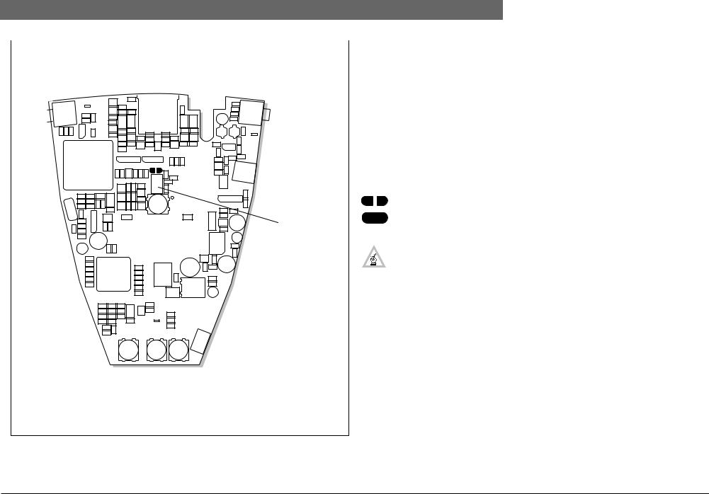
Digital Congress Network | Installation and Operating Manual | Chapter 2 - Contribution Equipment en | 2-4
|
|
|
|
|
|
|
|
|
|
|
|
|
|
|
|
|
|
|
|
|
|
|
2.3.1 Adjustment setting discussion units |
||
|
|
|
|
|
|
|
|
|
|
|
|
|
|
|
|
|
|
|
|
|
|
|
The operational functionality of the delegate discussion units LBB 3530/xx, LBB 3531/xx and the |
||
|
|
|
|
|
|
|
|
|
|
|
|
|
|
|
|
|
|
|
|
|
|
|
chairman discussion units LBB 3533/xx, LBB 3534/xx, can be set by a solder spot J1. If a flashing LED |
||
|
|
|
|
|
|
|
|
|
|
Top |
ring is required when the speaker has only 60 seconds of speech time remaining, then the solder spot |
||||||||||||||
|
|
|
|
|
|
|
|
|
|
J1 must be closed. |
|
|
|||||||||||||
|
|
|
|
|
|
|
|
|
|
|
|
|
|
|
|
|
|
|
|
|
|
|
To locate the solder spot proceed as follows: |
||
|
|
|
|
|
|
|
|
|
|
|
|
|
|
|
|
|
|
|
|
|
|
|
Refer to FIG. 2-5 |
|
|
|
|
|
|
|
|
|
|
|
|
|
|
|
|
|
|
|
|
|
|
|
|
|
• Unscrew and remove the two retaining TorX™ screws located on the underside of the unit. |
||
|
|
|
|
|
|
|
|
|
|
|
|
|
|
|
|
|
|
|
|
|
|
|
• Carefully remove the units housing, and locate the printed circuit board. |
||
|
|
|
|
|
|
|
|
|
|
|
|
|
|
|
|
|
|
|
|
|
|
|
• On the printed circuit board remove the loudspeaker connector |
||
|
|
|
|
|
|
|
|
|
|
|
|
|
|
|
|
|
|
|
|
|
|
Solder spot J1 |
• Locate solder spot JI. |
|
|
|
|
|
|
|
|
|
|
|
|
|
|
|
|
|
|
|
|
|
|
|
|
|
• Set the units functionally (see below). |
||
|
|
|
|
|
|
|
|
|
|
|
|
|
|
|
|
|
|
|
|
|
|
|
• Once done, replace the loudspeaker connection and replace the units housing. |
||
|
|
|
|
|
|
|
|
|
|
|
|
|
|
|
|
|
|
|
|
|
|
|
|||
|
|
|
|
|
|
|
|
|
|
|
|
|
|
|
|
|
|
|
|
|
|
|
Solder spot J1 |
|
|
|
|
|
|
|
|
|
|
|
|
|
|
|
|
|
|
|
|
|
|
|
|
|
Open (default) |
: |
Normal operation |
|
|
|
|
|
|
|
|
|
|
|
|
|
|
|
|
|
|
|
|
|
|
Loudspeaker |
Closed |
: |
Microphone LED ring will begin to flash when the last 60 seconds of |
|
|
|
|
|
|
|
|
|
|
|
|
|
|
|
|
|
|
|
|
|
|
|
|
speech time remains |
|
|
|
|
|
|
|
|
|
|
|
|
|
|
|
|
|
|
|
|
|
|
|
connector |
|
|
|
|
|
|
|
|
|
|
|
|
|
|
|
|
|
|
|
|
|
|
|
|
|
|
|
|
|
|
|
|
|
|
|
|
|
|
|
|
|
|
|
|
|
|
|
|
|
|
|
|
NOTE: If J1 is ‘closed’ when the ‘Voice’ activation mode is selected, the microphone LED |
||
|
|
|
|
|
|
|
|
|
|
|
|
|
|
|
|
|
|
|
|
|
|
|
ring will remain lit when speaking into the microphone. |
||
|
|
|
|
|
|
|
|
|
|
|
|
|
|
|
|
|
|
|
|
|
|
|
|
|
|
Bottom
Layout of Discussion unit ‘Printed Circuit Board’
FIG. 2-5 Discussion unit, functional adjustment using solder spot J1
Bosch Security Systems | 04-2003 | 3922 988 43318 en |
LBB 3533/xx and LBB 3534/xx Chairman Discussion Unit |
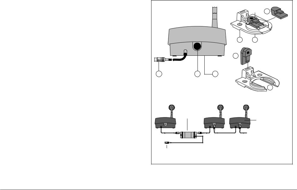
Digital Congress Network | Installation and Operating Manual | Chapter 2 - Contribution Equipment |
en | 2-5 |
|
|
2.3.2 Interconnection details discussion units
All discussion units include connectors for loop-through connection of one unit to the other (i.e.‘daisy chain’). FIG. 2-6 shows the connectors and the interconnection method used.
Key to symbols (FIG. 2-6 )
1.2 m long cable terminated with a 6-pole circular connector.
2.6-pole socket for loop-through from other system units.
3.Recessed microswitch for resetting the unit’s address (De-Init).
2.3.3 Mounting discussion units (FIG. 2-6)
In portable systems, discussion units can be free-standing on a level surface - such as a table-top. In permanent installations, the units can be nut/bolt mounted using the 2 x M3 threaded holes under the unit. In such an installation, the units cable securing clamp can be removed from its cable entry and modified, allowing its 2 m cable to be neatly run through a hole directly under the table-top surface (see opposite). For cable clamp modification, remove the cable clamp at the rear of the unit by unscrewing the clamps two securing screws (A) . Once removed, use a sharp cutting tool to remove the small insert (B) from its housing. Run the units cable through the cable run and secure it into the free cable entry using the removed insert (B) as shown in (D).
Rear view Discussion unit |
|
|
|
|
|
|
B |
|
|
A |
A |
|
|
D |
|
1 |
2 |
3 |
|
|
|
|
C |
|
Trunk Cable Splitter |
|
|
|
LBB 4114/00 |
|
|
|
|
|
Discussion unit |
|
|
|
(rear view) |
|
|
|
LBB 3530/xx |
|
|
|
LBB 3531/xx |
|
|
|
LBB 3533/xx |
|
|
|
LBB 3534/xx |
|
To Central Control Unit (CCU) |
|
|
FIG. 2-6 |
Interconnections discussion unit (rear view) |
|
|
Bosch Security Systems | 04-2003 | 3922 988 43318 en |
LBB 3533/xx and LBB 3534/xx Chairman Discussion Unit |
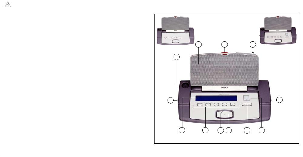
Digital Congress Network | Installation and Operating Manual | Chapter 2 - Contribution Equipment |
|
en | 2-6 |
|||
|
|
|
|
|
|
2.4 |
LBB3544/00, LBB3545/00andLBB3546/00 |
Rear, side and under views (FIG. 2-9 and FIG. 2-10) |
|
||
|
Delegate conference units (Concentus) |
12. |
*1 x 3.5 mm jack socket for headset/external microphone |
|
|
|
13. 2 x 3.5 mm stereo jack sockets for headphones (1 at each side of the unit). |
|
|||
Intended for table-top and flush-mounting, the delegate conference units enable participants to |
14. |
2 x Rotary volume control for headphones (1 at each side of the unit) |
|
||
15. |
Securing screw M3 for pluggable microphone (use Allen-key) |
|
|||
actively join in a discussion (i.e. speaking and listening).The unit includes a connection for a pluggable |
|
||||
16. 6-pole socket for loop-through from other system units |
|
||||
microphone type LBB 3549/00 or LBB 3549/50 and a microphone on/off button. Delegate unit types |
|
||||
LBB 3545/00 and LBB 3546/00 includes a language channel selector, and LC-display to select the |
17. 2 m (6.5ft.) long cable terminated with 6-pole circular connector |
|
|||
required language channel when used in combination with an interpretation system. |
18. Modular jack-socket for intercom handset LBB 3555/00 |
|
|||
|
NOTE: Delegate unit LBB 3544/00 does not include a language channel selector, head- |
19. |
2x M3 guide holes for unit mounting (using custom built fixing bracket/strap) |
|
|
|
20. |
Recessed micro-switch for resetting the unit’s address (DE-INIT). |
|
||
|
phone/headset connections and volume controls. |
|
|||
|
21. |
4 x securing screws for unit housing |
|
||
|
|
|
|||
Controls and Indicators (FIG. 2-7) (version illustrated LBB 3546/00)
*Not applicable to delegate units LBB 3544/00
**Not applicable to delegate units LBB 3545/00
1.XLR socket for ‘uni-directional’ condenser microphone (LBB 3549/00 or LBB 3549/50
(see 2.6) with illuminated LED light-ring to indicate microphone active (not active in ‘Voice’ activated mode). See Chapter 2.3.1 ‘Adjustment settings discussion units’.
2.Loudspeaker.The loudspeaker is automatically muted when the microphone is on.
3.Microphone ON indication (RED)
4.* **ID-chip-card reader for delegate identification.
5.*Numeric 1.5-digit LC-display for visual indication of the selected language channel.The display is activated once headphones are inserted in to the units jack socket.
6.*Up/down channel select keys for use in combination with the numeric display.
7.Microphone On/Off or request-to-speak button.
8.MicrophoneON indication (bi-colour LED green = ‘request-to-speak’, red = ‘microphone ON’)
9.5 soft-keys with confirmation indicators (yellow LEDs) for use in combination with the units graphic LC-display provides the following (not applicable for *LBB 3544/00 and **LBB 3545/00): To display:
-Conference information
-User information
-Individual messages
To participate in the following voting procedures
-Parliamentary voting (‘PRESENT’,‘No’,‘Abstain’,‘Yes’)
-Multiple choice or opinion poll voting (Numerals: 1 to 24 max.)
-Audience response voting (Rating scale - -, -, O, +, + +)
10.* **Graphical 2-line x 40 character LC-display (15 Chinese characters only) with back-lighting for displaying the following:
-Conference related information
-User information
-Individual messages
-Voting information and results
LBB 3544/00 |
LBB 3545/00 |
2 |
3 |
4 |
1
LBB 3546/00
14 |
14 |
10 |
9 |
8 |
7 |
6 |
5 |
NOTE: see 2.3.1 ‘Adjustment settings CONCENTUS units’.
FIG. 2-7 Delegate conference units LBB 3544/00, LBB 3545/00 and LBB 3546/00
Bosch Security Systems | 04-2003 | 3922 988 43318 en |
LBB 3544/00, LBB 3545/00 and LBB 3546/00 Delegate conference units (Concentus) |
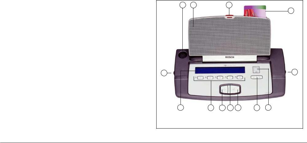
Digital Congress Network | Installation and Operating Manual | Chapter 2 - Contribution Equipment |
|
en | 2-7 |
|||
|
|
|
|
|
|
2.5 |
LBB 3547/00 Chairman Conference Unit |
Rear, side and under views (FIG. 2-9 and FIG. 2-10) |
|
||
|
(Concentus) |
12. |
1 x 3.5 mm jack socket for headset/external microphone |
|
|
|
13. |
2 x 3.5 mm stereo jack sockets for headphones (1 at each side of the unit). |
|
||
The unit provides access to the DCN systems main functions of listening to the floor via the units |
14. |
2 x Rotary volume control for headphones (1 at each side of the unit) |
|
||
15. |
Securing screw M3 for pluggable microphone (use Allen-key) |
|
|||
built-in loudspeaker, speaking and control of delegate microphones using a priority key, control of |
|
||||
16. |
6-pole socket for loop-through from other system units |
|
|||
voting sessions, the viewing of displayed messages, language channel selection and monitoring via |
|
||||
headphones and an ID card reader facility.The ID-card reader - for insertion of an ID-card - allows the |
17. |
2 m (6.5ft.) long cable terminated with 6-pole circular connector |
|
||
chairman to be identified by the system allowing access to the functions of the chairman unit. |
18. |
Modular jack-socket for intercom handset LBB 3555/00 |
|
||
The chairman unit uses a pluggable microphone LBB 3549/00 or LBB 3549/50 (not included), |
19. |
2x M3 guide holes for unit mounting (using custom built fixing bracket/strap) |
|
||
20. |
Recessed micro-switch for resetting the unit’s address (DE-INIT). |
|
|||
microphone on/off button, built-in graphical LC-display, five soft-keys with LED indicators, and a |
|
||||
21. |
4 x securing screws for unit housing |
|
|||
priority key.The priority key sets all currently active delegate microphones in the system to off |
|
||||
allowing the chairman to take over the control of the meeting.
Controls and indicators (FIG. 2-8)
1.XLR socket for ‘uni-directional’ condenser microphone (LBB 3549/00 or LBB 3549/50
(see FIG. 2-6)) with illuminated LED light-ring to indicate microphone active (not active in ‘Voice’ activated mode).
2.Loudspeaker.The loudspeaker is automatically muted when the microphone is on.
3.Microphone ON indication (RED)
4.ID-chip-card reader for chairman identification.
5.Numeric 1.5-digit LC-display for visual indication of the selected language channel.The display switches on when the plug of the headphones are inserted in to the jack socket.
6.Up/down channel select keys for use in combination with the numeric display (5)
7.Microphone On/Off button
8.MicrophoneON indication (bi-colour LED green = ‘request-to-speak’, red = ‘microphone ON’) (Permanently on in ‘Voice activated mode).
9.Priority key, which when pressed emits a chime sound (if programmed) while temporarily muting all active delegate units.The chairman’s microphone remains active for as long as the priority button is kept pressed.This key can also be used to cancel all active delegate units and remove all delegates waiting to speak from the request list (if programmed in the CCU).
10.5 x Soft-keys with confirmation indicators (yellow LEDs) are used in combination with the units graphical LC-display to provide the following functions:
- Microphone control, such as ‘Cancel all Request’, Cancel all speakers and requests.
-Voting control (Start, Hold, Restart, Stop)
-Voting participating function (No, Abstain,Yes)
-Messages
11.Graphical 2-line x 40 character LC-display (15 Chinese characters only) with back-lighting for displaying the following:
-Conference related information
-User information
-Individual messages
-Voting information and results
1 |
2 |
3 |
4
Front view
14 |
14 |
11 |
10 |
9 |
8 |
7 |
6 |
5 |
NOTE: see 2.3.1 ‘Adjustment settings CONCENTUS units’.
FIG. 2-8 LBB 3547/00 Chairman unit
Bosch Security Systems | 04-2003 | 3922 988 43318 en |
LBB 3547/00 Chairman Conference Unit (Concentus) |

Digital Congress Network | Installation and Operating Manual | Chapter 2 - Contribution Equipment |
en | 2-8 |
|
|
|
|
Transportable state (collapsed) |
|
Rear |
|
|
|
|
|
Left side |
|
|
|
|
|
|
|
|
|
|
|
|
|
|
|
|
|
|
|
|
|
|
|
|
|
|
|
|
1 |
|
|
|
|
|
|
|
|
|
15 |
|
|
|
|
3 |
|
|
|
|
Microphone |
|
|
|
|
|
|
|
|
|
release screw |
|
|
|
|
|
|
16 |
17 |
18 |
(for transportation) |
|
|
|
|
|
|
|
|||
|
|
|
|
Right side |
Under |
|
|
|
|
|
|
|
|
|
|
|
|
|
|
|
|
|
|
|
|
|
|
|
19 |
12 |
13 |
14 |
|
|
|
|
|
|
|
|
|
|
|
|
20 |
|
|
|
|
Not applicable |
|
|
DE-INIT |
|
|
|
|
||
to LBB 3544/00 |
|
|
|
|
|
|
|||
|
|
|
|
|
|
|
|||
|
|
|
|
|
|
|
21 |
|
|
|
|
|
|
|
|
|
16 |
From |
next unit |
|
|
|
|
|
|
|
|
||
|
|
|
|
|
To previous unit |
|
|
|
|
|
|
14 |
13 |
|
17 |
From Intercom handset |
18 |
||
|
|
|
|
||||||
|
|
|
|
|
|
LBB 3555/00 |
|
|
|
FIG. 2-9 Concentus units (side views) |
FIG. 2-10 Concentus units (rear and underside views) |
Bosch Security Systems | 04-2003 | 3922 988 43318 en |
LBB 3547/00 Chairman Conference Unit (Concentus) |

Digital Congress Network | Installation and Operating Manual | Chapter 2 - Contribution Equipment
2.5.1 Adjustment setting conference (Concentus) units
The operational functionality of the delegate conference (Concentus) units LBB 3544/00,
LBB 3545/00, LBB 3546/00, and the chairman conference units LBB 3547/00 can be set by solder spots 1070, 1170, 1171 and 1172 located on the units PCB.
To locate the solder spots proceed as follows:
•Refer to FIG. 2-10
• Unscrew and remove the 4 securing TorX™ screws located on the underside of the unit.
•Carefully remove the units housing, and locate the printed circuit board (FIG. 2-11).
•If necessary carefully remove the loudspeaker connector.
•Locate solder spots 1070, 1170, 1171 and1172 (FIG. 2-11).
•Set the units functionally (see below).
•Once done, replace the loudspeaker connection and replace the units housing.
en | 2-9
Concentus PCB (Top view rotated 90°)
1007
Functionality
Solder spots 1070
Open (default) |
: |
Normal operation |
Closed |
: |
Microphone LED ring will begin to flash when the last 60 seconds of |
|
|
speech time remains. |
NOTE: If 1070 is ‘closed’ when the ‘Voice’ activation mode is selected, the microphone LED ring will remain lit when speaking into the microphone. If a flashing LED ring is required when the speaker has only 60 seconds of speech time remaining, then solder spot 1070 must be closed.
Solder spots 1170
Open (default) |
: |
Normal operation |
Closed |
: |
The intercom function is no longer available (see Note) |
NOTE: If 1170 is closed, the functionality of solder spots 1171 and 1172 is available (for example - an external make contact can be connected to PINS 1 and 2 of the intercom connector for ‘FRAude’ (Fraud push_button) and ‘FINger’ (Finger print reader) operation.
Solder spots 1171
Open (default) |
: |
Normal operation |
Closed |
: |
‘FRAude’ bit is available via the intercom connector (see Note) |
Solder spots 1172 |
|
|
Open (default) |
: |
Normal operation |
Closed |
: |
‘FINger’ bit is available via the intercom connector (see Note) |
NOTE: If solder spot 1170 is closed a choice of only one of the functions is available ‘FRAude’ or FINger’ NOT both.
Solder spot 1070
Solder spot 1170
Solder spot 1172
Solder spot 1171
Intercom handset connector
FIG. 2-11 PCB layout conference (Concentus) units
Bosch Security Systems | 04-2003 | 3922 988 43318 en |
LBB 3547/00 Chairman Conference Unit (Concentus) |
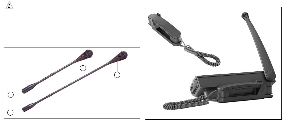
Digital Congress Network | Installation and Operating Manual | Chapter 2 - Contribution Equipment |
en | 2-10 |
|
|
2.6LBB 3549/00, LBB 3549/50 Pluggable Microphones
The pluggable flexible stem microphones LBB 3549/00 and LBB 3549/50 are unidirectional microphones intended for use with delegate units LBB 3544/00, LBB 3545/00, LBB 3546/00, chairman unit LBB 3547/00 and flush mounted microphone control panel LBB 3537/20.
Type number description:
LBB 3549/00 Pluggable microphone with flexible stem
Mic. stem length: 310 mm (12.2 in) (incl. mic.)
LBB 3549/50 As LBB 3544/00 but with extended stem length: 480 mm (18.8 in) (incl. mic.)
NOTE: See also Chapter 2.1.2 LBB 3537/20 Pluggable Microphone control panels.
Controls and Indicators
1.Unidirectional microphone, mounted on a flexible stem with built-in pop and windshield. The microphones include an illuminated indicator ring for microphone active status.
Interconnection
2.5-pole XLR-connector for connection to the delegate units LBB 3544/00, LBB 3545/00, LBB 3546/00, chairman unit LBB 3547/00 and microphone control panel LBB 3537/20.
LBB 3549/00
1
1
LBB 3549/50
2.7LBB 3555/00 Intercom handset
The Intercom handset enables private two-way vocal communication between conference participants.The handset is hard-wired to the cradle by a coiled cable (0.5 m (19.68 in) coiled, 2 m uncoiled (78.74 in) hard wired to the cradle (FIG. 2-13).The cradle output cable is terminated with a 6-pole modular jack connector for connection to a conference units, interpreter desks, Multi-purpose connection units and the PC Network card.
When used in permanent installations, the handset is easily mounted to a table-top or wall using the screw holes in the cradle. In portable systems the handset can be simply attached to an Interpreter desk with the aid of a mounting plate LBB 3556/00.
For installing on an Interpreter desk LBB 3520 refer to Chapter 3.1.2.
Intercom handset
LBB 3555/10
Interpreter desk
LBB 3520/10
2
2 
FIG. 2-12 Pluggable microphones LBB 3549/00 and LBB 3549/50 |
FIG. 2-13 LBB 3555/00 Intercom Handset |
Bosch Security Systems | 04-2003 | 3922 988 43318 en |
LBB 3549/00, LBB 3549/50 Pluggable Microphones |
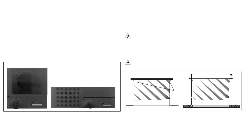
Digital Congress Network | Installation and Operating Manual | Chapter 2 - Contribution Equipment |
en | 2-11 |
|
|
2.8Flush-mounted Contribution equipment
DCN’s broad range of flush mounted units form the building blocks for creating individual system contribution units for use in custom built solutions.The flush-mounted units are intended for use in fixed installations, where portability is not required.The units can be neatly installed in to either tabletops or seat armrests.The range of flush-mounted units available, provides all the functions and facilities offered by the table-top contribution units. For example a delegate unit can be created by combining a Multi-purpose connection unit LBB 3540/15 or Dual Audio Interface Unit LBB 3535/00. These units being the main components when creating flush-mounted solutions in combination with
the following units:
Type No. |
Description |
LBB 3536/00-/10 |
Hand microphones |
LBB 3537/00, /50 |
Microphone control panel |
LBB 3537/10 |
Chairman microphone control panel with priority |
LBB 3537/20 |
Pluggable microphone control panel |
LBB 3538/00 |
Loudspeaker panel |
LBB 3539/00 |
Blank mounting panel |
LBB 3541/00 |
Delegate voting control panel* |
LBB 3542/00 |
Delegate/chairman voting control panel with LC-display* |
LBB 3543/15 |
Chip-Card reader panel* |
LBB 3555/00 |
Intercom handset* |
LBB 3524/xx + |
Electronic Channel Selector Panel (connected to DCN trunk-line) |
LBB 3526/10 |
|
|
|
* Applicable to Multi-purpose Connection Unit LBB 3540/15 only
Portrait
Landscape
FIG. 2-14 Orientation flush-mounted units
All flush-mounted units are available in standard sizes of 40 x 120 mm (1.57 x 4.72 in) with the exception of the flush-mounted loudspeaker unit LBB 3538/00 which has a dimension of 80 x 120 mm (3.14 x 4.72 in) and the Delegate/chairman voting control panel LBB 3542/00 which has a dimension of 80 x 240 mm (3.14 x 9.44 in).The dimensions of the flush-mounted units allow units to be neatly installed and positioned along side each other in either a portrait or landscape type configuration.
Mounting
All DCN’s flush-mounted units include a ‘click-to-fit’ mechanism, enabling units to be secured into cutouts on table-tops or the armrest of seats in a landscape or portrait type format.
Two methods are used to mount the flush-mounted units. Method 1 is used when mounting units into a metal surface and method 2, used when mounting units into a wooden surface.
Method 1 (mounting into a metal surface)
The ‘click-to-fit’ mechanism available on all flush mounting unit is used to secure the units into cutouts on table-tops or the armrests of seats etc. Additional screws are needed when mounting LBB 3537/xx Control Panel with microphone.The recommended method when installing the units, is to install them into a 2 mm (0.07 in) thick metal panel.The metal panel is used as the platform for securing the units.The panel needs to be cut-out according to the units template.
NOTE: Table top mounting is also possible for certain units with the Table-top housing LBB 3527/00. Refer to Chapter 2.24.
Method 2 (mounting into a wooden surface)
Units are secured by screws using the holes available on each unit. All units include drill guide holes located under the front cover of each flush-mounted unit.The guide holes are used for guidance when drilling the units screw holes.
General
For cut-out templates and dimensions when physically installing the units refer to Chapter 13. “Mechanical data”.
Metal mounting |
Wood mounting |
|
Drill- |
|
holes |
|
‘Click-to-fit’ |
|
mechanism |
2mm (0.07”) Metal plate |
Wood surface |
FIG. 2-15 Flush mounting in metal and wooden surfaces
Bosch Security Systems | 04-2003 | 3922 988 43318 en |
Flush-mounted Contribution equipment |
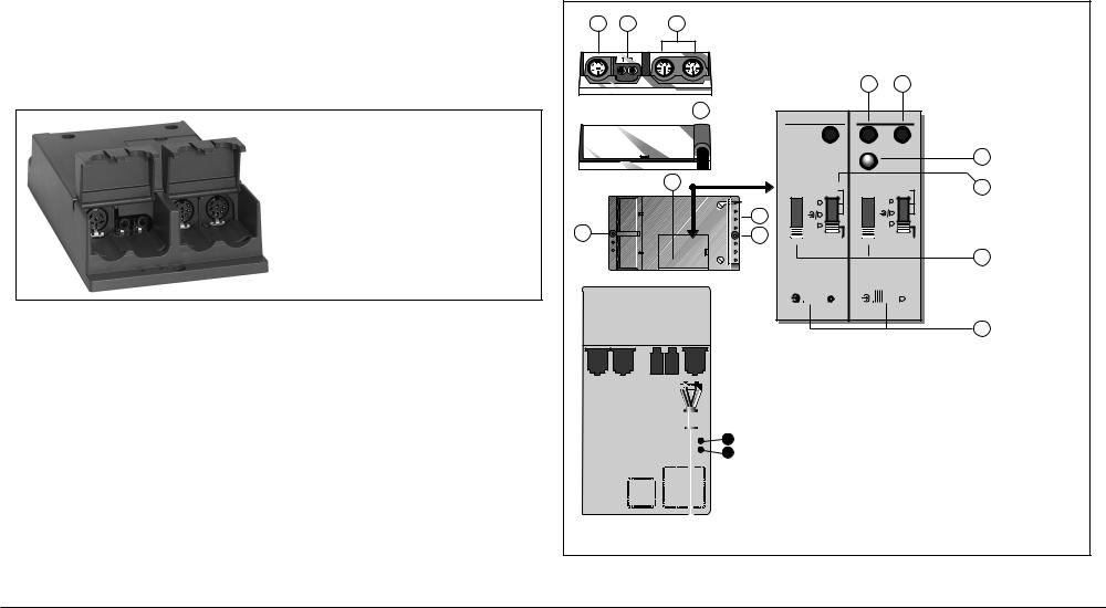
Digital Congress Network | Installation and Operating Manual | Chapter 2 - Contribution Equipment |
en | 2-12 |
|
|
2.9 LBB 3535/00 Dual Audio Interface unit
10.Initialization LED indicator.The LED illuminates when the unit is not being initialized.The LED is Off when the unit has been initialized.
The LBB 3535/00 allows a variety of microphones, as well as line sources, to be connected to the DCN system. The unit can be used in combination with the LBB 3536/xx Hand microphone when mounting in seat armrest etc., or with the LBB 3537/xx Microphone with Control Panel when flushmounting into table-tops etc.
The unit includes two separate inputs, each selectable for use with either a microphone or line input source. Each input can be assigned with its own seat number, providing two delegate or chairman positions.
Two 3.5 mm jack sockets provide the connection to headphones or to loudspeaker panels LBB 3538/ 00, or a combination of both.The output is switched off when the corresponding input is switched on.
FIG. 2-16 LBB 3535/00 Dual Audio Interface Unit
Controls, Indicators and Interconnection (Chapter 2.17)
1.6-pole circular connector for loop through system.
2.2 x loudspeaker output connectors (marked 1 and 2) (3.5 mm jackplug socket).The loudspeaker is muted automatically when the corresponding microphone is on.
3.2 x balanced audio input (marked 1 and 2) for line level (-12 dBV) or microphone level (-60 dBV) sources with or without a phantom power supply). (2 x 8-pole 262° DIN-type socket).
4.2 m long cable terminated with a moulded 6-pole circular connector.
5.2 x screw holes for securing the unit.
6.Switch panel with cover.
7.Tie-wrap holes for securing connected cables.
8.Initialization button (INIT) used for initializing the unit during installation. Also used to reset the unit’s address (De-Init).
9.Input 1 and 2: ± 3 dB input level potentiometer for fine adjustment.
11.Selector switch for selecting an asymmetrical microphone input, or a symmetrical microphone/ line level input, or a symmetrical microphone input with Phantom power supply (12 V/680 Ohm).
12.Input attenuation selection of: 0, 6, 12 or 18 dB. Factory setting: 6 dB.
13.Microphone or line level select switch.
1 2 3
1 |
2 |
1 |
2 |
8 |
9 |
|
|
|
|
||
|
|
|
4 |
2 |
|
|
|
|
1 |
|
|
|
|
+/-3dB |
Init |
+/-3dB |
10 |
|
|
|
|
|
|
|
|
6 |
|
Sym |
|
Sym |
11 |
|
|
dB |
dB |
|||
|
|
|
P12 |
|
||
|
|
18 |
P12 |
18 |
|
|
|
7 |
12 |
|
12 |
|
|
|
6 |
|
6 |
|
|
|
5 |
|
|
|
|
||
5 |
0 |
Asym |
0 |
Asym |
|
|
|
Attn |
|
||||
|
|
|
Attn |
|
|
12
INPUT LEVEL |
INPUT LEVEL |
|
||||||
-12 dBV |
|
|
-60 dBV |
-12 dBV |
|
|
-60 |
dBV |
|
|
|
|
|
|
|
|
|
13
|
|
|
|
|
|
|
|
|
|
|
|
|
|
|
|
|
|
|
|
|
|
|
|
|
|
|
|
|
|
|
|
|
|
|
|
|
|
|
|
|
|
|
|
J2 |
J1 |
J2 |
Function |
|
|
|
|
||||
|
|
|
|
J1 |
|
|
|
|
|
|
|
Open |
Open |
Mic. on inputs 1 and 2 (factory setting) |
|
|
|
|
|
||||
|
|
|
|
|
|||
|
|
IC 1 |
|
Closed |
Open |
Chairman mic. on input 2, priority panel on input 1 |
|
|
|
|
|
|
|||
IC 8 |
|
|
|
|
|||
|
|
|
|
|
|
|
|
|
|
|
|
|
Open |
Closed |
Ambient mic. on input 2 |
|
|
|
|
|
|
|
|
|
|
|
|
|
|
|
|
FIG. 2-17 LBB 3535/00 Dual Audio Interface Unit
Bosch Security Systems | 04-2003 | 3922 988 43318 en |
LBB 3535/00 Dual Audio Interface unit |
Loading...