


Mini-PROTEAN® 3 Cell
Instruction Manual
Catalog Numbers 165-3301 165-3302
For Technical Service Call Your Local Bio-Rad Office or in the U.S. Call 1-800-4BIORAD (1-800-424-6723)
|
Table of Contents |
|
|
|
Page |
Section 1 |
General Information.................................................................................... |
1 |
1.1 |
Introduction ................................................................................................................ |
1 |
1.2 |
Components................................................................................................................ |
2 |
1.3 |
Specifications ............................................................................................................. |
4 |
1.4 |
Chemical Compatibility ............................................................................................. |
4 |
1.5 |
Safety .......................................................................................................................... |
5 |
Section 2 Set Up and Basic Operation........................................................................ |
5 |
|
2.1 |
Gel Cassette Preparation ............................................................................................ |
5 |
2.2 |
Mini-PROTEAN 3 Cell Assembly and Sample Loading ......................................... |
8 |
2.3 |
Gel Electrophoresis .................................................................................................... |
9 |
Section 3 Separation Theory and Optimization...................................................... |
10 |
|
3.1 |
Introduction .............................................................................................................. |
10 |
3.2 |
SDS-PAGE (Laemmli) Buffer System.................................................................... |
11 |
3.3 |
Native PAGE............................................................................................................ |
12 |
Section 4 Reagent Preparation and Stock Solutions .............................................. |
13 |
|
4.1 |
Volumes Required Per Gel ...................................................................................... |
13 |
4.2 |
SDS-PAGE (Laemmli) Buffer System.................................................................... |
13 |
4.3 |
Discontinuous Native PAGE (Ornstein-Davis)....................................................... |
15 |
4.4 |
Continuous Native PAGE ........................................................................................ |
16 |
Section 5 |
References ................................................................................................... |
18 |
Section 6 |
Maintenance ............................................................................................... |
18 |
Section 7 |
Troubleshooting.......................................................................................... |
19 |
Section 8 Product Information and Accessories ..................................................... |
21 |
|
Section 9 |
Warranty Information............................................................................... |
23 |
Section 1
General Information
1.1 Introduction
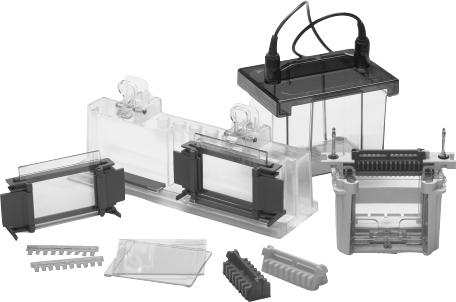
The Mini-PROTEAN 3 cell runs both hand cast gels and Ready Gel precast gels interchangeably. The Mini-PROTEAN 3 system includes a casting stand and glass plates with permanently bonded gel spacers that simplify hand casting and eliminate leaking during casting. The cell can run one or two gels, and the mini tank is compatible with other Bio-Rad electrode modules for tank blotting, 2-D electrophoresis, and electro-elution.
Fig. 1. Mini-PROTEAN 3 system components.
1
1.2 Components
To get the best performance from your Mini-PROTEAN 3 cell, familiarize yourself with the components by assembling and disassembling the cell before using it (refer to Figures 1 and 2).
Spacer Plate |
The Spacer Plate is the taller glass plate with gel spacers |
|
permanently bonded. Spacer Plates are available in 0.5 mm, 0.75 mm, |
|
1.0 mm, and 1.5 mm thicknesses, which are marked directly on |
|
each Spacer Plate. |
Short Plate |
The Short Plate is the shorter, flat glass plate that combines with the |
|
Spacer Plate to form the gel cassette sandwich. |
Casting Frame |
The Casting Frame, when placed on the benchtop, evenly aligns |
|
and secures the Spacer Plate and the Short Plate together to form the |
|
gel cassette sandwich prior to casting. |
Gel Cassette Assembly |
One Casting Frame, a Spacer Plate, and a Short Plate form one Gel |
|
Cassette Assembly. |
Casting Stand |
The Casting Stand secures the Gel Cassette Assembly during gel |
|
casting. It contains pressure levers that seal the Gel Cassette |
|
Assembly against the casting gaskets. |
Gel Cassette Sandwich |
A Spacer Plate and Short Plate with polymerized gel form a Gel |
|
Cassette Sandwich after casting. |
Combs |
A selection of molded combs is available. |
Buffer Dam |
The molded, one-piece buffer dam is used when running only one |
|
gel. |
Electrode Assembly |
The Electrode Assembly holds the Gel Cassette Sandwich. It houses |
|
the sealing gasket, the upper and lower electrodes and the |
|
connecting banana plugs. The anode (lower electrode) banana plug |
|
is identified with a red marker and the cathode (upper electrode) |
|
banana plug with a black marker. |
Clamping Frame |
The Clamping Frame holds the Electrode Assembly and Gel |
|
Cassette Sandwich in place. Its pressure plates and closure cams |
|
seal the Gel Cassette Sandwich against U-shaped gaskets on the |
|
Electrode Assembly to form the inner buffer chamber. |
Inner Chamber |
The Electrode Assembly, two Gel Cassette Sandwiches or one gel |
|
cassette sandwich and a buffer dam, and the Clamping Frame form |
|
the Inner Chamber. |
Mini Tank and Lid |
The Mini Tank and Lid combine to fully enclose the inner chamber |
|
during electrophoresis. The lid cannot be removed without |
|
disrupting the electrical circuit. The Mini Tank and Lid are also |
|
compatible with other Bio-Rad electrode modules for blotting, first |
|
dimension 2-D, and electro-elution. |
2

Banana Plugs
Anode banana plug (red)
Notch on U-Shaped Gasket
Gel Cassette
Sandwich
Pressure Plate
Cams
Fig. 2. Assembling the Mini-PROTEAN 3 cell.
Casting


 Frame
Frame
Pressure cams in
"open position"
Pressure cam pivot point
Lid
Cathode banana plug


 (black)
Electrode
Assembly
Inner
Chamber
Assembly
Clamping
Frame
Mini Tank


 Spring loaded levers
Casting Stand without gaskets. Gaskets must be used for proper seal.
Fig. 3. Assembling the Mini-PROTEAN 3 Casting Frame and Casting Stand.
3
1.3 Specifications
Casting Stand* |
|
|
Polycarbonate |
|
|
|
|
|
Pin, Retaining Ring, and Spring |
Stainless Steel |
|
|
|
|
|||
Casting Frames* |
|
|
Polysulfone |
|
|
|
|
|
Gray Gaskets |
|
|
Silicone Rubber (gray) |
|
|
|||
Clamping Frame** |
|
|
Glass-filled liquid crystal polymer (Vectra™) |
|||||
Pressure Plate and Cams |
|
Polycarbonate |
|
|
|
|
||
Electrode Assembly |
|
|
Glass-filled liquid crystal polymer |
|
||||
Electrodes |
|
|
Platinum wire, 0.010 inches diameter |
|||||
Gasket, electrode inner core |
|
Silicone Rubber (green) |
|
|
||||
Mini Tank and Lid |
|
|
Molded Polycarbonate |
|
|
|||
Sample Loading Guides† |
|
Delrin™ |
|
|
|
|
|
|
Combs* |
|
|
Polycarbonate |
|
|
|
|
|
Maximum Sample Volume Per Well |
|
|
|
|
|
|
||
# wells |
Well width |
0.5 mm |
0.75 mm |
1.0 mm |
1.5 mm |
|||
5 |
12.7 mm |
— |
70 |
µl |
105 |
µl |
160 |
µl |
9 |
5.08 mm |
— |
33 |
µl |
44 |
µl |
66 |
µl |
10 |
5.08 mm |
22 µl |
33 |
µl |
44 |
µl |
66 |
µl |
15 |
3.35 mm |
13 µl |
20 |
µl |
26 |
µl |
40 |
µl |
IPG |
76.2 mm |
— |
|
— |
420 |
µl |
730 |
µl |
Prep/2-D |
|
|
|
µl |
|
µl |
|
µl |
Reference well |
3.1 mm |
— |
13 |
17 |
30 |
|||
Sample well |
71.7 mm |
— |
310 |
µl |
400 |
µl |
680 |
µl |
Overall Size of cell |
|
|
16 cm (L) x 12 cm (W) x 18 cm (H) |
|
||||
Gel Size |
|
|
8 cm (W) x 7.3 cm (H) |
|
|
|
||
Inner Plate |
|
|
10.1 cm (W) x 7.3 cm (H) |
|
|
|||
Outer Plater |
|
|
10.1 cm (W) x 8.3 cm (H) |
|
|
|||
Precast Gel Compatibility |
|
Ready Gels |
|
|
|
|
||
Voltage Limit |
|
|
600 VDC and 15 watts |
|
|
|||
Shipping Weight |
|
|
2.0 kg |
|
|
|
|
|
1.4 Chemical Compatibility
Mini-PROTEAN 3 components are not compatible with acetone, ethanol, or butanol. Use of organic solvents voids all warranties. Call 1-800-4-BIORAD or your local Bio-Rad representative for technical information regarding additional chemical compatibility of the Mini-PROTEAN 3 cell with various laboratory reagents.
The Mini-PROTEAN 3 combs are not compatible with repeated exposure to 100% TEMED. Rubbing the combs with TEMED prior to casting will destroy the structural integrity of the combs over time.
*US patent No. 6,162,342
**US patent No. 5,632,877
† US patent No. 5,656,145
4
1.5 Safety
Power to the Mini-PROTEAN 3 cell is supplied by an external DC voltage power supply (not included). The output of this power supply must be isolated from external ground to insure that the DC voltage output floats with respect to ground. All Bio-Rad power supplies meet this important safety requirement. Regardless of the power supply used, the maximum specified operating parameters for the Mini-PROTEAN 3 cell are as follows:
• |
600 VDC |
maximum voltage limit |
• |
15 watts |
maximum power limit |
• |
50 °C |
maximum ambient temperature limit |
The current to the cell enters the unit through the lid assembly which provides a safety interlock to the user. The current to the cell is broken when the lid is removed. Always turn off the power supply before removing the lid. Do not attempt to use the cell without the safety lid.
Important: This Bio-Rad product is designed and certified to meet *EN61010-1 safety standards. Certified products are safe to use when operated in accordance with the instruction manual. This instrument should not be modified or altered in any way. Alteration of this instrument will
•Void the warranty
•Void the EN61010-1 certification, and
•Create a potential safety hazard.
Bio-Rad is not responsible for any injury or damage caused by use of this instrument for purposes other than those for which it is intended or by modifications of the instrument not performed by Bio-Rad or an authorized agent.
* EN61010-1 is an internationally accepted electrical safety standard for laboratory instruments.
Section 2
Set Up and Basic Operation
2.1 Gel Cassette Sandwich Preparation
Hand Cast Gels
1.Glass Cassette and Casting Stand Assembly
Note: Ensure the casting stand, casting frames, and glass plates are clean and dry before setting up the casting stand assembly. During regular use, a powder residue may build up behind the pressure cams of the casting frame at the pivot point. This powder should be removed before each use.
a.Place the Casting Frame upright with the pressure cams in the open position and facing forward on a flat surface.
b.Select a Spacer Plate of the desired gel thickness and place a Short Plate on top of it (see Figure 4a).
c.Orient the Spacer Plate so that the labeling is "up". Slide the two glass plates into the Casting Frame, keeping the Short Plate facing the front of the frame (side with pressure cams) (see Figure 4b).
Note: Ensure both plates are flush on a level surface and labeling on the Spacer Plate is oriented correctly. Leaking may occur if the plates are misaligned or oriented incorrectly.
d.When the glass plates are in place, engage the pressure cams to secure the glass cassette sandwich in the Casting Frame (see Figure 4c). Check that both plates are flush at the bottom.
5
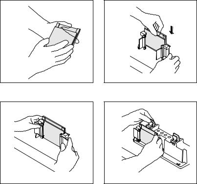
e.Engage the spring loaded lever and place the gel cassette assembly on the gray casting stand gasket. Insure the horizontal ribs on the back of the Casting Frame are flush against the face of the Casting Stand and the glass plates are perpendicular to the level surface. The lever pushes the Spacer Place down against the gray rubber gasket (see Figure 4d).
f.Repeat steps a–e for a second gel.
4a. Place a Short Plate on top of the Spacer Plate.
4b. Slide the two plates into the Casting Frame keeping the Short Plate facing front.
4c. Lock the pressure cams to secure the glass plates.
4d. Secure the Casting Frame in the Casting Stand by engaging the spring loaded lever.
Fig. 4. Assembling the Mini-PROTEAN 3 casting stand and frame.
2.Gel Casting
a. Discontinuous Polyacrylamide Gels
i.Place a comb completely into the assembled gel cassette. Mark the glass plate 1 cm below the comb teeth. This is the level to which the resolving gel is poured. Remove the comb.
ii.Prepare the resolving gel monomer solution by combining all reagents except APS and TEMED. (Refer to Section 4 for gel formulations.) Degas the solution under vacuum for at least 15 minutes. Do not use a sink water aspirator.
iii.Add APS and TEMED to the degassed monomer solution and pour to the mark using a glass or disposable plastic pipette. Pour the solution smoothly to prevent it from mixing with air.
iv. Immediately overlay the monomer solution with water or t-amyl alcohol. Note: If water is used, add it slowly and evenly to prevent mixing. Do not overlay w/butanol or isobutanol.
v. Allow the gel to polymerize for 45 minutes to 1 hour. Rinse the gel surface completely with distilled water. Do not leave the alcohol overlay on the gel for more than 1 hour because it will dehydrate the top of the gel.
6
 Loading...