


Microplate Manager Software

Microplate
Manager
®
5.0 PC
User Guide
Life Science
Group
Bio-Rad
Laboratories
2000 Alfred Nobel Drive
Hercules, CA 94547
P/N 4000138 RevB

Catalog Number 170-9520
Bio-Rad Technical Services Department
Open Monday–Friday, 8:00 a.m. to 4:00 p.m., Pacific Standard Time.
Phone: (800) 424-6723, option 2, option 3
(510) 741-6576
Fax: (510) 741-5802
E-mail: LSG.TechServ.US@Bio-Rad.com (U.S.)
LSG.TechServ.Intl@Bio-Rad.com (International)
Notice:
No part of this publication may be reproduced or transmitted in any form or by any
means, electronic or mechanical, including photocopy, recording, or any information
storage or retrieval system, without permission in writing from Bio-Rad.
Microplate Manager is a registered trademark and Ultramark is a trademark of
Bio-Rad Laboratories. Windows and Windows NT are registered trademarks of Microsoft
Corporation. All other trademarks and registered trademarks are of their respective
companies.
Copyright © 1999 by Bio-Rad Laboratories. All rights reserved.

Warranty
Bio-Rad Laboratories warrants that the Microplate Manager software shall
substantially conform, in all operational features, to Bio-Rad’s current specifications
as published in Bio-Rad’s user and installation guides and that, when properly
installed, it will be free of material defects which affect system performance.
The Purchaser must notify Bio-Rad in writing, within 30 days of delivery of the
software (not including delivery of any subsequent modifications to the software), of
any defect. If the software is found to be defective by Bio-Rad, Bio-Rad’s sole
obligation under this warranty is to remedy the defect in a manner consistent with
Bio-Rad’s regular business practices. For a defect which adversely affects the
performance of the software, Bio-Rad shall use its best efforts to cure such defect as
soon as reasonably practicable after receipt of Purchaser’s notice. For minor defects,
Bio-Rad shall use its best efforts to correct such minor defects in the next release of
its software. If, however, Bio-Rad is unable to cure a major defect within 90 days of
receipt of Purchaser’s notice, Purchaser shall have the option to cancel this
agreement, whereupon Bio-Rad shall refund only the software fees paid.
The warranties set forth in this agreement are in lieu of all other representations and
warranties, expressed or implied, including warranties of merchantability and fitness
for a particular purpose and any other statutory or common-law warranty. Bio-Rad on
its own behalf expressly disclaims and excludes any and all such other
representations and warranties. Liability of Bio-Rad to Purchaser, if any, for breach
of warranty, or any other claim relating to this agreement, shall be limited to the total
amount of software fees paid by purchaser to Bio-Rad. In no event shall Bio-Rad be
liable for incidental or consequential damages, loss of business or profits, special or
indirect damages of any nature whatsoever. No amendment, waiver, or other
alteration of the warranties in this agreement may be made except by mutual
agreement in writing.
Purchaser agrees that Bio-Rad’s liability arising out of contract, negligence, strict
liability in tort or warranty shall not exceed the amount of software license fees paid
by Purchaser.
This manual and the software (computer program) described in it are copyright BioRad Laboratories, Inc. with all rights reserved worldwide. Under the copyright laws,
iii

this manual and the software program contained herein may not be copied, in whole
or in part, without the prior written consent of Bio-Rad, except in the normal use of
the software or to make a backup copy. This exception does not allow copies to be
made for others, whether or not sold, but all of the materials purchased (with all
backup copies) may be sold, given or loaned to another person. Under the law,
copying includes translating into another language or format.
A multi-use license may be purchased to allow the software to be used on more than
one computer owned by the purchaser, including a shared disk system.
iv

Table of Contents
1. Introduction..............................................................1
1.1 Overview of Microplate Manager...................................................1
1.2 Types of Files ...............................................................................3
1.3 New Features in Version 5.0.........................................................4
2. Installation and Setup..............................................7
2.1 Instrument Specifications..............................................................7
2.1.1 Host Computer and Operating System ........................................7
2.1.2 Microplate Readers ......................................................................7
2.2 Connecting the Microplate Readers to the Host Computer...........7
2.3 Attaching the Hardware Protection Key........................................8
2.4 Installing Microplate Manager.......................................................8
2.5 Starting Microplate Manager......................................................... 9
2.6 Selecting a Serial Port ..................................................................9
2.7 Setting Filters.............................................................................. 10
2.7.1 Ultramark Setup .........................................................................10
2.7.2 Model 550 Setup ........................................................................11
2.8 Preferences................................................................................11
2.9 Sample Data Files.......................................................................13
3. Getting Started.......................................................15
3.1 Menus, Toolbars, and Other Features........................................15
v

3.2 Opening and Saving Files...........................................................17
3.3 Reading Data from Other Applications........................................17
3.4 Quick Start..................................................................................17
3.5 Typical Scenarios........................................................................18
4. Templates...............................................................23
4.1 Opening a Template...................................................................23
4.1.1 Opening an Existing Template ...................................................23
4.1.2 Opening a New Template...........................................................24
4.2 Viewing the Template.................................................................28
4.3 Features of a Template...............................................................29
4.4 Formatting a Template................................................................33
4.4.1 Step 1. Define the Assays.........................................................34
4.4.2 Step 2. Define the Well Types...................................................36
4.4.3 Step 3. Enter the Concentrations of the Standards...................40
4.4.4 Step 4. Enter Dilutions of Unknowns.........................................41
4.4.5 Step 5. Select Regression Curve ..............................................43
4.4.6 Step 6. Select External Standards.............................................44
4.4.7 Step 7. Saving the Template.....................................................47
5. Protocols................................................................49
5.1 Features Common to All Protocols .............................................51
5.1.1 Reader Identification...................................................................51
5.1.2 Selecting a Template..................................................................51
5.1.3 Setting the Reading Parameters ................................................53
5.1.4 Incubator Controls (Ultramark and Model 550 only)...................53
5.1.5 Mix Settings................................................................................54
5.1.6 Reader Door (Ultramark only)....................................................54
5.1.7 Reports.......................................................................................55
5.1.8 Running a Protocol.....................................................................57
5.1.9 Saving a Protocol .......................................................................57
vi

5.2 Features Unique to Endpoint Protocols.......................................58
5.3 Features Unique to Kinetic Protocols ..........................................59
5.3.1 Reading Sets..............................................................................60
5.3.2 Analysis Options.........................................................................61
5.4 Features Unique to Multiple Plate Protocols...............................64
6. Data Formatting and Reports................................71
6.1 Summary of Available Reports....................................................71
6.2 Saving Your Data........................................................................73
6.3 Manually Editing Data.................................................................73
6.4 Identifying Outliers......................................................................74
6.5 Editing or Replacing the Template in a Data File........................76
6.6 Reports.......................................................................................77
6.6.1 Labels.........................................................................................77
6.6.2 Raw Image Report (Ultramark only)...........................................79
6.6.3 Reports Available for Endpoint and Multiple Plate Data Only.....83
6.6.4 Reports Available for Kinetic Data Only .....................................84
6.6.5 Reports Common to all Reading Types .....................................88
6.7 Standard Curve Comparison.......................................................97
6.8 Standard Curve Fitting................................................................98
7. Data Output..........................................................101
7.1 Printing.....................................................................................101
7.2 Data Import and Export.............................................................102
7.2.1 Exporting Data..........................................................................103
7.2.2 Importing Data..........................................................................104
7.2.3 Kinetic Data Formats................................................................104
vii

8. Quick Guides........................................................107
8.1 Creating a New Template.........................................................107
8.2 Creating and Running a New Kinetic Prot ocol with a
Stored Template.......................................................................108
8.3 Creating and Running a New Kinetic Prot ocol and Cr eating
the Template Simultaneously....................................................109
8.4 Creating and Running a New Endpoint Prot ocol with a
Stored Template.......................................................................110
8.5 Creating and Running a New Endpoint Prot ocol and
Creating the Template Simultaneously.....................................111
8.6 Creating and Running a Multiple Plate Protocol with a
Stored Template.......................................................................112
8.7 Creating and Running a New Multiple Plate Protocol and
Creating the Template Simultaneously.....................................113
9. Glossary...............................................................115
10. Ordering Information...........................................117
Index...........................................................................119
Appendix A. Menus ..................................................123
viii

List of Figures
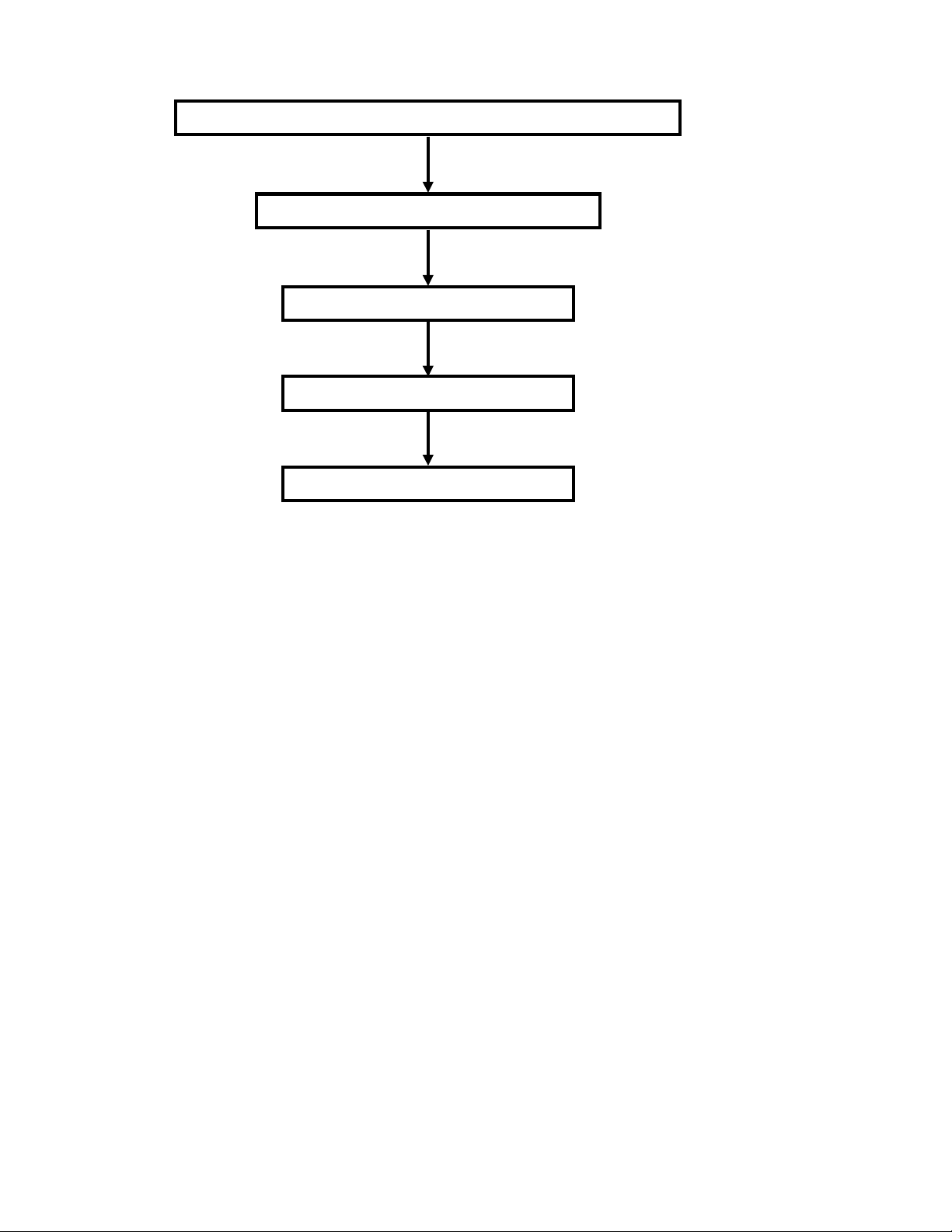
Figure 1. Workflow of Microplate Manager............................................................2
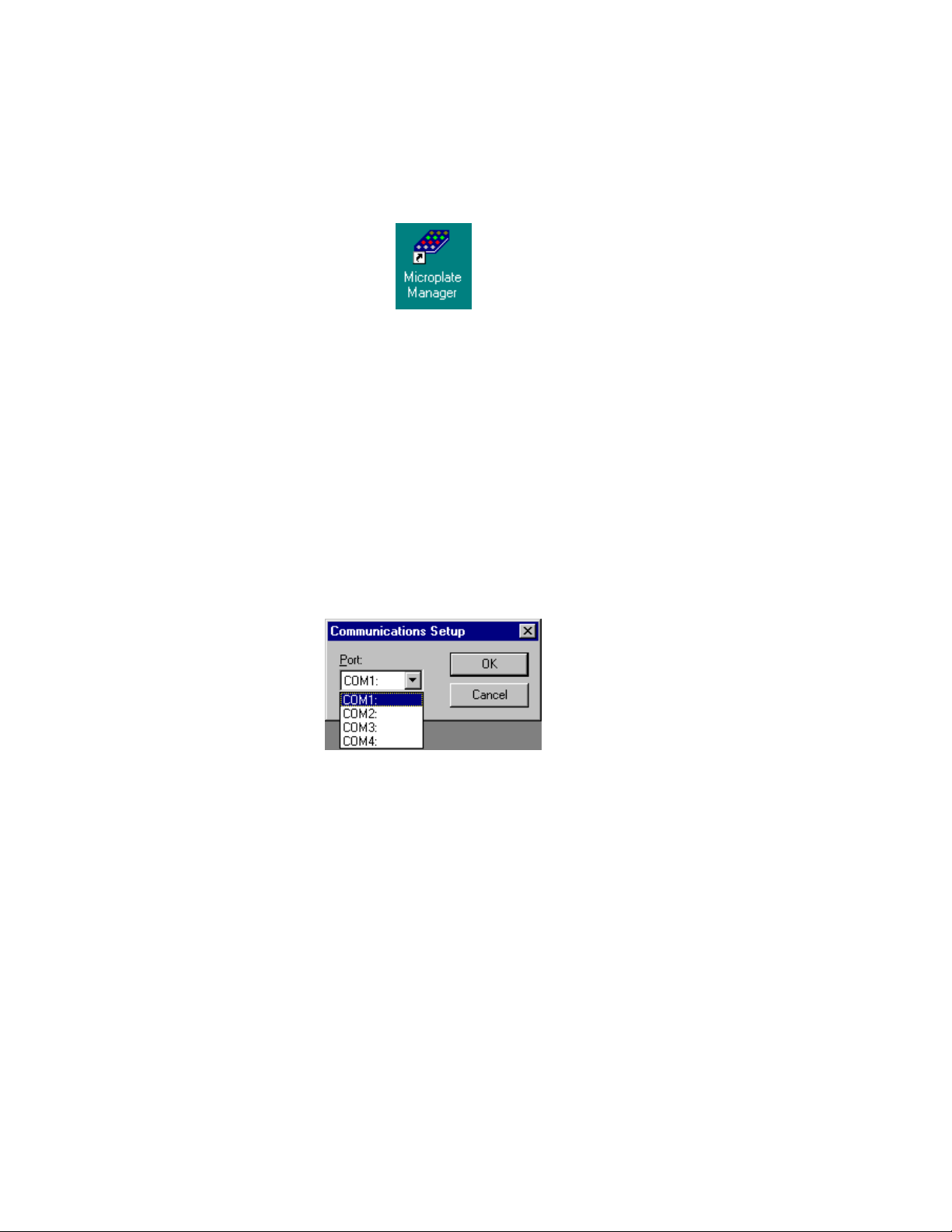
Figure 2. Microplate Manager desktop icon. .........................................................9
Figure 3. Communications Setup dialog box.........................................................9
Figure 4. Ultramark Setup dialog box..................................................................10
Figure 5. Model 550 Setup dialog box.................................................................11
Figure 6. Preferences dialog box.........................................................................12
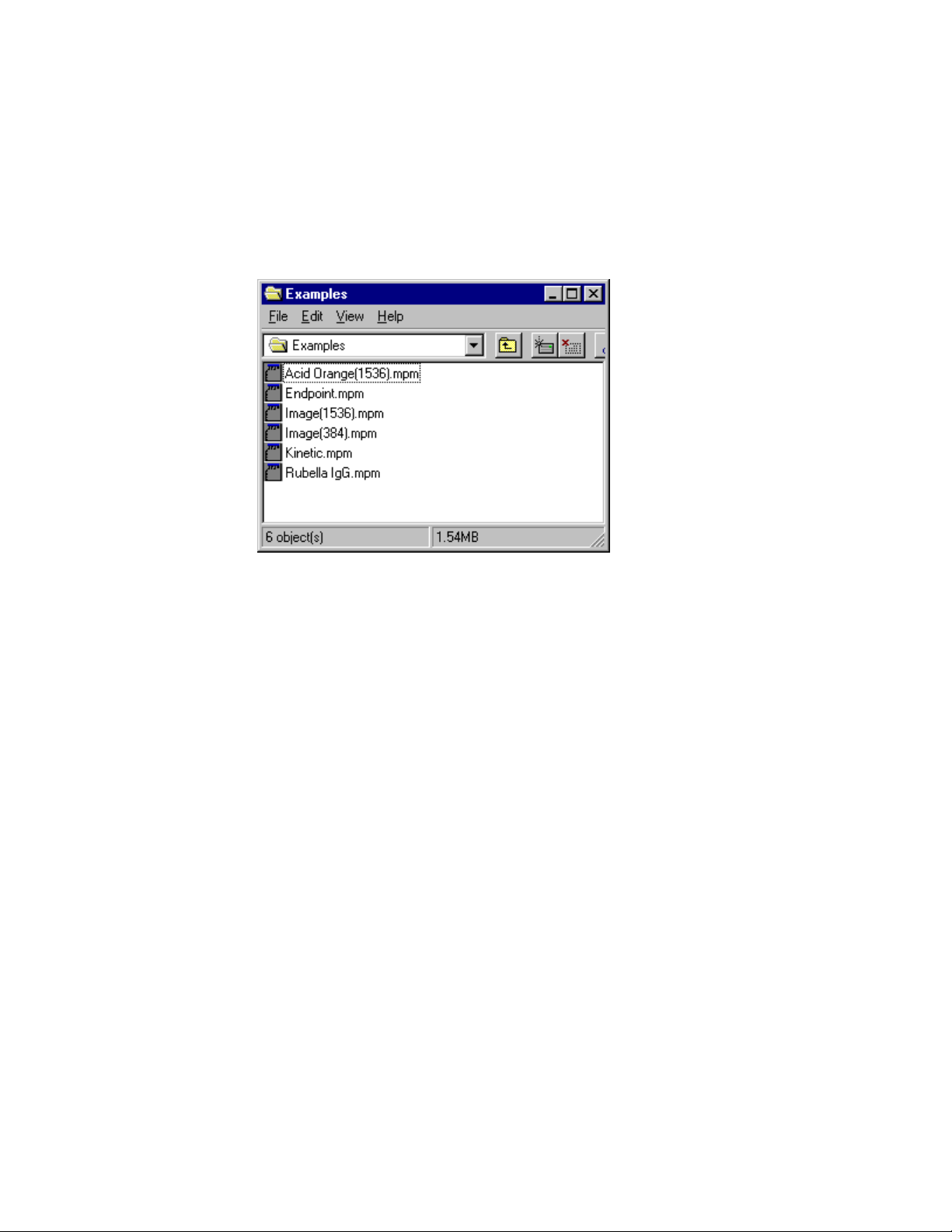
Figure 7. Examples directory...............................................................................13
Figure 8. Default menu bar and main toolbar......................................................15
Figure 9. Example of commands available by clicking right mouse button.........16
Figure 10. Performing an endpoint reading.........................................................19
Figure 11. Defining the Reading Sets..................................................................20
Figure 12. Comparing external and internal standards. ......................................22
Figure 13. Selecting a template...........................................................................24
Figure 14. Creating a custom template. ..............................................................25
Figure 15. Defining the format of a plate.............................................................26
Figure 16. Entering the physical dimensions of your plate..................................27
Figure 17. Example of cursor feedback in a template.........................................28
Figure 18. Well Info dialog box............................................................................29
Figure 19. Blank 12 x 8 template.........................................................................30
Figure 20. Example of a plate template with two different assays defined..........32
Figure 21. Format menu and template toolbar....................................................33
Figure 22. Defining an assay with the Assay tool................................................35
Figure 23. Assay Information dialog box. ............................................................36
Figure 24. Autofilling a row of standards. ............................................................37
Figure 25. Defining a replicate groups of unknowns. ..........................................38
Figure 26. Defining multiple standard replicate groups in a row..........................39
Figure 27. Edit Standards dialog box. .................................................................40
Figure 28. Edit Unknowns dialog box..................................................................42
Figure 29. Standard Curve dialog box.................................................................43
Figure 30. External Standards dialog box. ..........................................................45
Figure 31. Selecting the source file for the external standards. ..........................45
Figure 32. Selecting the source assay for your external standards.....................46
Figure 33. Example of a protocol dialog box. ......................................................50
Figure 34. Selecting a new template in a protocol dialog box. ............................52
Figure 35. Reading Parameters in the protocol dialog box. ................................53
Figure 36. Incubator settings...............................................................................54
ix

Figure 37. Ultramark reader door controls. .........................................................54
Figure 38. Reports dialog box for endpoint and multiple plate protocols.............55
Figure 39. Define Labels dialog box....................................................................56
Figure 40. Example of a running protocol............................................................57
Figure 41. Features unique to an endpoint protocol dialog box. .........................58
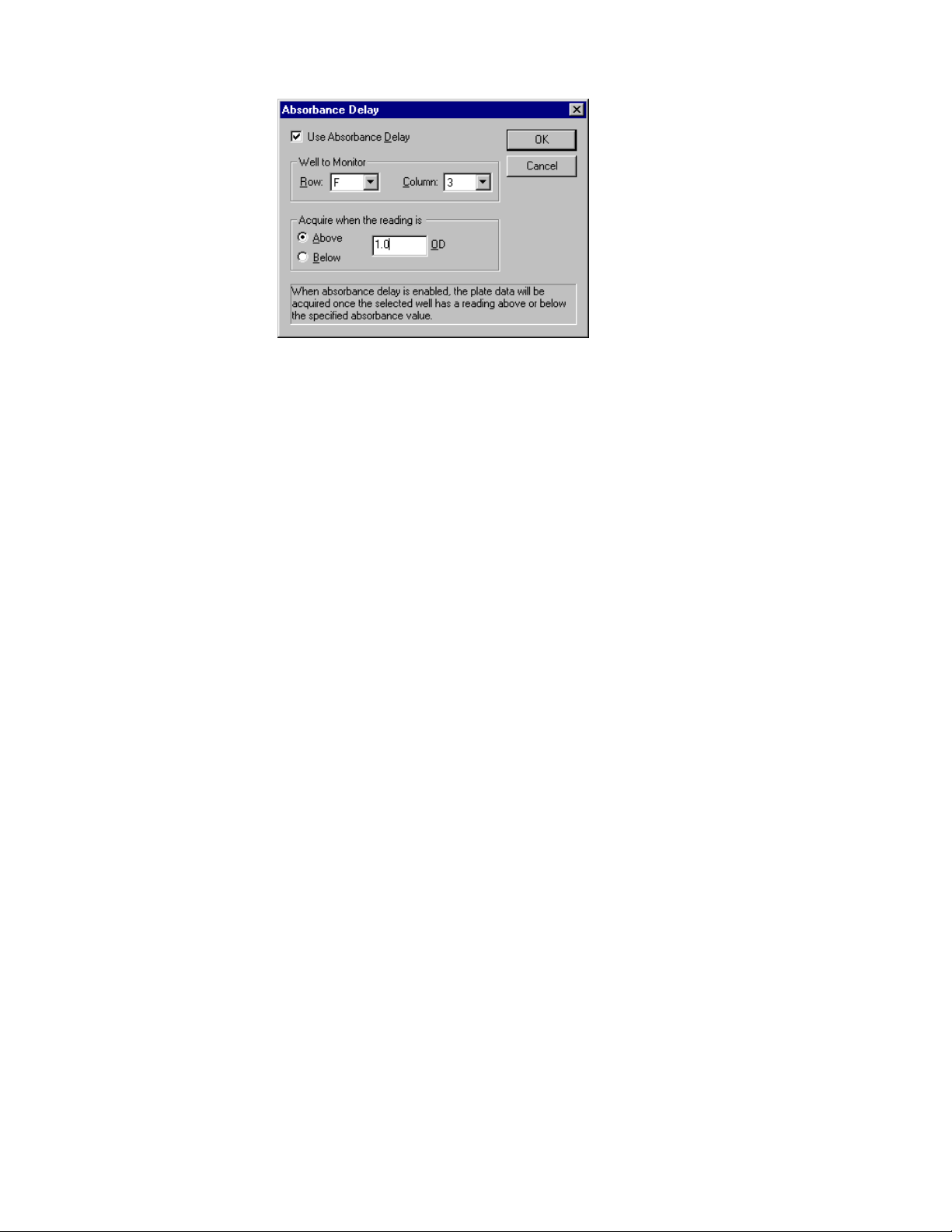
Figure 42. Absorbance Delay dialog box.............................................................59
Figure 43. Features of a kinetic protocol dialog box............................................60
Figure 44. Analysis Options in the kinetic protocol dialog box. ...........................62
Figure 45. Features of a Multiple Plate Protocol dialog box................................65
Figure 46. Plate Handler Options dialog box.......................................................66
Figure 47. Absorbance Delay dialog box.............................................................68
Figure 48. Editing raw data..................................................................................73
Figure 49. Select Outliers dialog box...................................................................75
Figure 50. Define Labels dialog box....................................................................77
Figure 51. Dialog box for adding or inserting labels. ...........................................78
Figure 52. Fill Labels dialog box..........................................................................78
Figure 53. Example of a Raw Image Report (1536-well plate)............................79
Figure 54. Image menu. ......................................................................................80
Figure 55. Close-up of a microplate image. ........................................................82
Figure 56. Raw Data Report................................................................................83
Figure 57. Absorbance Report. ...........................................................................84
Figure 58. Velocity Report...................................................................................84
Figure 59. Adjusted Velocity Report....................................................................85
Figure 60. Kinetic Correlation Coefficient Report. ...............................................86
Figure 61. Kinetic Standard Errors Report. .........................................................86
Figure 62. Kinetic Plots Report............................................................................87
Figure 63. Kinetic Zoom Plot. ..............................................................................88
Figure 64. Limit Report........................................................................................89
Figure 65. Limits dialog box.................................................................................90
Figure 66. Matrix Report......................................................................................91
Figure 67. Control Report....................................................................................92
Figure 68. Normalization Report..........................................................................93
Figure 69. Standard Curve Report. .....................................................................94
Figure 70. Unknown Concentration Report.........................................................96
Figure 71. Analysis of Variance box....................................................................97
Figure 72. Print dialog box.................................................................................101
Figure 73. Export to Excel dialog box................................................................104
x

1. Introduction
This manual assumes that you are familiar with your computer and standard
Windows commands and functions, such as opening, closing, and saving files, and
moving and clicking your mouse.
Some of the features and functions in Microplate Manager may be slightly different
depending on whether you are using the Ultramark, Model 550, or Benchmark
microplate reader. These differences are noted in the text.
1.1 Overview of Microplate Manager
Microplate Manager is designed to collect, analyze, and output data from Bio-Rad’s
Ultramark, Model 550, and Benchmark microplate readers. It runs as a Windows 95,
Windows 98, or Windows NT 4.0 application on a computer that is directly
connected to the reader. It features a standard Windows
menus, toolbars, and keyboard shortcuts.
Using Microplate Manager, you first select the type of reading you want to perform
and specify the layout of your microplate. Then you capture your data using the
microplate reader. Finally, you display your reports and print and/or export your data.
®
interface, with pulldown
1
Microplate Manager User Guide
Select Type of Reading (Endpoint, Kinetic, or Multiple Plate Protocol)
Define or Select Microplate Template
Take Reading
Generate and Format Reports
Print/Export Data
Figure 1. Workflow of Microplate Manager
Microplate Manager can perform three general types of microplate readings. These
are called “protocols.”
• Endpoint protocols are used to acquire a single absorbance reading from each
well.
• Kinetic protocols are used to acquire a series of absorbance readings from each
well over a user-defined interval. These protocols are used to calculate reaction
velocities.
• Multiple plate protocols are used with a stack loader to collect endpoint data
from a series of plates. Multiple plate protocols save each endpoint data set in a
separate file.
First you select the type of protocol you want to create. Then you specify the settings
for your particular protocol and define or select a template for your microplate.
2

Chapter 1. Introduction
Finally you take the reading. If you want to use the pa rticular protoc ol you’ve created
again, you can save it as a file.
Once absorbances have been read, you can save them as a data file and display them
in a selection of reports. Your data can be viewed, printed, or exported to other
applications.
1.2 Types of Files
There are two types of files used by Microplate Manager. Protocol files contain the
settings for reading a microplate. Data files contain the data from the reading and any
formatting associated with that data.
Protocol Files
A protocol file contains the parameters of a reading. It includes such information as
mixing times and measurement wavelengths. Each of the three protocol types
(endpoint, kinetic, and multiple plate) is slightly different, to accommodate the
different parameters used in each type. File names for protocols have the extensions
.epr (endpoint reading), .mpr (multiple plate reading), or .kpr (kinetic plate reading).
The protocol file also includes a plate template. The template specified in the
protocol file is copied into the data file at the completion of a plate reading. If there
is no template specified in the protocol file, then the default template is copied into
the data file. Defining a template in the protocol file before a reading allows you to
create data files that contain all the information necessary to evaluate the absorbance
data and automatically generate the desired reports.
(You can edit or replace the template in the data file after a reading. However,
changes made to the protocol file template after a reading are not updated in the data
file.)
You may specify labels for reports; these are stored in the protocol file.
A list of reports to be printed and/or displayed at the end of a run are saved in the
protocol file.
3

Microplate Manager User Guide
Data Files
The data file contains the raw data from the microplate reader. It has the extension
.mpm.
For an endpoint reading, this data consists of the individual absorbance readings
from the wells on the microplate. For a kinetic reading, this data is the time course
series of the individual absorbance readings. A multiple-plate reading creates a new
data file for each plate; each file contains endpoint absorbance measurements.
The data file also contains a plate template, which contains all the information
necessary to analyze the absorbance data, including a description of the assay, well
types, concentrations, dilutions, and the regression method used for computing
unknowns from standards. When the data file is first created after the ab sorbance data
is collected, the template associated with the protocol file is copied into the data file.
You can later edit the template or completely replace it with a template from another
data file.
Finally, the data file includes some information on how the plate was read (e.g.,
measurement wavelength, date/time of reading).
1.3 New Features in Version 5.0
This version of Microplate Manager features an enhanced user interface with image
display and grid overlay features. Some of the new features of the software include:
• Flexible plate definition to handle images reads of plates from 1 to 1,536 wells,
including drag-and-drop well layout and multilevel undo when formatting
images.
• Improvements in template formatting, including automatic scrolling when
formatting large plates, noncontiguous well selection for cha nging assay and
replicate set asso ciation, better handling of renumbering standard s and unknowns
on densely formatted plates, and autofilling for rapidly assigning standard and
unknown replicate sets.
• Automated setup. The software automatically identifies the microplate reader
and establishes the connection to the reader.
4

Chapter 1. Introduction
• Major improvements in associating protocols and templates.
• More flexibility in tagging outliers in replicate sets.
• Up to 12 different assays on one plate, each with its own blanks, controls, and
standards.
• More status bar and cursor feedback in templates and reports, including well
information and cursor positions.
• External standards and standard curve checking. A quantitative method for
comparing two standard curves is now available. A statistical analysis of the
comparison is provided.
• Improved display of graphics reports such as standard curve and kinetic zoom.
o
• Incubator temperature adjustments as small as 0.2
• Improved handling of multipage printouts for larger plates.
• Permanent tagging of user-edited or imported data on screen and in printouts.
• Fully integrated simulated scanner for demos and practice runs, capable of
producing simulated data.
• Complete reading protocols. Reading parameters, plate template, analysis
options, and print settings may be saved for repeated applications.
C.
• Auto-scaling of kinetic data in Kinetic Zoom Plot windows.
5


2. Installation and Setup
2.1 Instrument Specifications
2.1.1 Host Computer and Operating System
Microplate Manager will run under Windows 95, Windows 98, or Windows NT 4.0.
The host machine must be based on a Pentium Intel class CPU or higher. It should
have a hard disk of at least 200 MB, and a minimum of 16 MB RAM. It must have a
monitor and video card capable of displaying 256 colors at 1024 by 768 resolution.
There must be a SCSI-2 port available for connecting to the reader. A mouse is
required to use the software. A parallel port is required in order to print reports
directly from the PC.
The Ultramark communicates with the host computer via a SCSI-2 connection. You
can use the SCSI-2 cable and Adaptec card provided by Bio-Rad (cat. no. 170-9521)
or purchase them from any computer store.
The Model 550 and Benchmark microplate readers communicate with the host
computer via a standard serial port and cable.
2.1.2 Microplate Readers
Microplate Manager 5.0 supports Bio-Rad’s Ultramark, Model 550, and Benchmark
microplate readers.
2.2 Connecting the Microplate Readers to the
Host Computer
A SCSI-2 cable and card (cat. no. 170-9521) are required to connect the Ultramark to
the host PC. Make sure all devices are turned off before making or changing cable
connections. See the hardware manual for details.
7

Microplate Manager User Guide
A serial cable is included with the Model 550 or Benchmark and is used to connect
the instrument to the host PC. Make sure all devices are turned off before making or
changing cable connections. See the hardware manual for details.
2.3 Attaching the Hardware Protection Key
A hardware protection key (HPK) is included with this version of Microplate
Manager. You must attach the HPK to your computer before you can run Microplate
Manager.
Before attaching the HPK, turn off your computer. If you have a printer attached to
your computer’s parallel port, turn that off as well.
The HPK attaches to the parallel port on the back of your PC. If a printer cable is
attached to this port, disconnect it. After you have attached the HPK, you can attach
the printer cable to the key itself and restart your computer and printer.
The HPK has a driver that is automatically installed when you install Microplate
Manager.
2.4 Installing Microplate Manager
Insert the Setup disk (Disk 1) into the floppy disk drive on your computer. On your
Windows taskbar, click the Start button, then select Run. Type a:\setup in the field,
and click on OK.
The installer will prompt you to insert the remaining disks. The default program
directory is C:\Program Files\Bio-Rad\Microplate Manager. You can select a
different directory when prompted to do so by the installer.
The installer will place a startup icon on your desktop and create a Microplate
Manager directory on your Windows Start menu. When the installer is finished, click
on the Finish button.
8
Chapter 2. Installation and Setup
2.5 Starting Microplate Manager
To start Microplate Manager, click on the application icon on your desktop or select
Microplate Manager from the Programs directory on your Start menu.
Figure 2. Microplate Manager desktop icon.
The software will open, displaying the menu bar, main toolbar, main application
window, and status bar.
2.6 Selecting a Serial Port
The Ultramark connects to the computer via the SCSI port. If you are connecting to a
microplate reader other than the Ultramark, you can specify the serial port connection
by selecting Communications Setup from the OPTIONS menu in Microplate
Manager. This opens a dialog box in which you can select one of the available ports
on your computer.
Figure 3. Communications Setup dialog box.
9

Microplate Manager User Guide
When you open a protocol, Microplate Manager will look first for a reader at the
serial port you select. If a reader is not found at that port, the software will scan the
remaining ports as well as the SCSI bus for a reader.
If a reader is found at a particular port, that port will be selected. If no reader is found
at any serial port or the SCSI port, you will receive an error message.
2.7 Setting Filters
If you change the filters in the Ultramark or Model 550 microplate readers, you can
specify the wavelengths of the new filters from within Microplate Manager.
(Benchmark users should refer to the hardware manual for instructions on changing
filter settings.)
2.7.1 Ultramark Setup
Select Ultramark Setup from the OPTIONS menu
Figure 4. Ultramark Setup dialog box.
For each filter, enter the appropriate wavelength. The wavelengths of the filters that
are shipped with the Ultramark will be included with your Ultramark documentation.
If you change any of the filters, you will need to change these settings.
10

Chapter 2. Installation and Setup
Click on OK to implement your changes.
2.7.2 Model 550 Setup
Select Model 550 Setup from the OPTIONS menu
Figure 5. Model 550 Setup dialog box.
For each filter, enter the appropriate wavelength. The wavelengths of the filters that
are shipped with the Model 550 will be included with your reader documentation. If
you change any of the filters, you will need to change these settings.
Click on OK to implement your changes.
2.8 Preferences
To set the user-defined preferences for Microplate Manager, select Preferences from
the FILE menu.
11

Microplate Manager User Guide
Figure 6. Preferences dialog box.
In the Preferences dialog box, you can enter or select the Default File Location for
opening and saving files. To select the directory, click on the “...” button next to the
text field and scroll thro ugh the directory tree. You can also type the full director y
path and name directly in the field. If an invalid path is entered, it will be ignored,
and the working directory will be used as the home directory.
Microplate Manager has a number of “warning” messages that pop up if you try to
perform certain operations. Those messages include a checkbox to disable the
warning (“Don’t show this warning again”). If you select that checkbox, and then
decide that you want to display the warning again, click on the Reset All Warnings
button in the Preferences dialog box.
If you are not connected to a microplate reader, the Allow Simulated Scanner
checkbox allows you to operate the software as if you were connected to an
Ultramark. In this mode, all the controls will appear active, but instead of real
readings, you will create “dummy” reports containing manufactured data. This is
useful for practice and demonstration purposes.
To enter simulated mode, the checkbox must be checked and, if you are connected to
a reader, the reader must be turned off.
When the simulated scanner function is enabled, you can also select Allow Random
Variations. This will generate random numbers in your simulated scans.
½ The Advanced button accesses additional preferences that should not be changed
except with the assistance of Bio-Rad support personnel.
12
Chapter 2. Installation and Setup
When you are finished making your selectio ns, click on the OK button.
2.9 Sample Data Files
Six sample data files are installed with Microplate Manager, in a directory called
Examples in your Microplate Manager directory on your hard drive.
Figure 7. Examples directory.
Clicking on any one of these data files will open Microplate Manager and display the
template for that file. Then you can view the sample data using the commands
described in Chapter 6.
13


3. Getting Started
3.1 Menus, Toolbars, and Other Features
Menu Bar
Microplate Manager has a standard menu bar with pulldown menus that include all
the commands and functions in the software. The available menus and menu items
are different depending on the specific actions you are performing.
For example, when the software first opens, the menus will include basic file opening
and set-up features. When you are formatting a template, the menus will change to
include functions for formatting a template. When you are creating a protocol, the
menus will change to include related functions. After you have read a microplate and
the data is displayed, the menus will change again to include functions for creating
different reports and exporting your data.
Toolbars
Microplate Manager has a main toolbar that contains standard file and formatting
tools . It is displayed below the menu bar. Display of the main toolbar can be toggled
on and off from the VIEW menu.
Figure 8. Default menu bar and main toolbar.
Other tools are associated with particular features of the software, and only appear
when you are using those features. For example, the template toolbar is only
displayed when you are formatting a template. It is located at the top of the template
form.
15

Microplate Manager User Guide
Right-click Commands
You can access many of the commands associated with the action you are currently
performing by using the right mouse button. For example, if you are in the process
of defining an assay on your template, clicking the right mouse button will display
many of the commands associated with that action. The commands are displayed in a
drop-down menu next to the cursor.
Figure 9. Example of commands available by clicking right mouse button.
Status Bar
The status bar appears at the bottom of the Microplate Manager window. If your
cursor is positioned over a button or menu command, a brief description of that
function will appear in the status bar.
In some reports (Raw Image, Standard Curve), the status bar indicates the position
of the cursor. It also indicates the position of the cursor when you are working with
templates.
Display of the status bar can be toggled on and off from the VIEW menu.
16

Chapter 3. Getting Started
3.2 Opening and Saving Files
Microplate Manager has two basic file types: Protocol files and data files. Protocol
files have a .kpr, .epr., or .mpr extension. Data files have a .mpm extension.
To open an existing protocol file or data file, select Open... from the FILE menu ,
select the name of the file you want to open, and click on the Open button.
To save a protocol file, select Save Protocol or Save Protocol As... from the FILE
menu. To save a data file, select Save Data/Template or Save Data/Template As...
from the FILE menu. If you are saving a new file or renaming an old file, enter the
new file name and click on the Save button.
See the individual chapters on templates (Chapter 4), protocols (Chapter 5), and data
and reports (Chapter 6) for more information.
3.3 Reading Data from Other Applications
The software will read files from the previous version of the Microplate Manager/PC
software (version 4.0.x). It also imports data in several ASCII formats, including tab
delimited and comma delimited (CSV). Kinetic data is imported from one of three
formats defined in Kinetic Collector PC: COL, ROW, MTX. The software will not
read native files from the Macintosh Microplate Manager software, but it will read
tab delimited files generated by the Macintosh Microplate Manager software.
Data from all reports can be copied onto the clipboard, as well as exported to a file in
either tab delimited or comma delimited formats. Both tab delimited and comma
delimited formats may be exported into Excel
®
.
3.4 Quick Start
To read a plate immediately, perform the following steps:
1. Turn on the plate reader and let it warm up. Prepare a microplate and place it in
the plate reader.
17

Microplate Manager User Guide
2. Open Microplate Manager.
3. Under the FILE menu, select New Endpoint Protocol, New Kinetic Protocol, or
New Multiple Plate Protocol, depending on the type of analysis you want to
perform. The protocol dialog box will open.
4. In the dialog box, select the size of your microplate from the Plate Type:
pulldown list and click on the Run button. The plate will be read and your raw
absorbance or velocity data will be displayed.
At this point, you can format the template, save and analyze the data, and generate,
display, and print any additional reports. (See the following chapters for information
about to perform these functions.)
3.5 Typical Scenarios
The following scenarios describe the workflow for typical kinds of analysis. Refer to
the following chapters for details on how to perform the particular functions.
Scenario 1. Endpoint Assay with Previously Formatted Template
You want to perform an endpoint assay using a template layout that you have already
defined. From the FILE menu, you select New Endpoint Protocol. This opens the
Endpoint Protocol dialog box. You enter Mix Time, Initial Wait, and Incubator
settings for the reader.
18
Chapter 3. Getting Started
Figure 10. Performing an endpoint reading.
You have a data file saved from a previous run with the template you want to use for
this plate, so you click on Pick Template... and choose that data file. Now that
everything is set, you click on the Run button.
After the reading is complete, the raw data values pop up. The plate template is also
displayed. Since the template already contains the concentrations of the standards,
you go straight to the Unknown Concentration Report (select Unknown
Concentration Report from the VIEW menu). You select Print... from the FILE
menu to print this report.
You decide that you will be repeating this operation frequently, so you go back to the
Endpoint Protocol dialog box. The Reports... button opens a dialog box in which
you specify the reports to view and/or print after each reading. Select the Unknown
Concentration Report for printing, and click on OK. You select Save Protocol from
the FILE menu and enter a file name to store this protocol on disk.
The next day, you want to repeat the protocol. Select the protocol file name from the
Open dialog box, place your plate in the reader, click on the Run button, and wait at
the printer for a hard copy of the new Unknown Concentration Report.
19

Microplate Manager User Guide
Scenario 2. Kinetic Assay
You want to perform a new kinetic assay. From the FILE menu, you select New
Kinetic Protocol. The Kinetic Protocol dialog box opens.
For this assay, you would like to make five readings at 21-second intervals followed
by 20 readings at one-minute intervals. You want to shake the plate for one second
before each of the first five readings.
To accomplish this, you define two reading sets. The first set has 5 repetitions, a 1second mix time, and a 22-second interval (the interval you want plus the mix time).
The second set has 20 repetitions, 0 seconds mix time, and a 60-second interval.
Interval includes
mix time
Figure 11. Defining the Reading Sets.
After inserting your 12 x 8 plate into the reader, you click on Run and the reader
begins collecting data. At this point, both the template and the Kinetic Plots Report
automatically pop up.
The Kinetic Plots Report shows a graph of absorbance versus time for each well. As
each reading is completed, the graphs are updated. After all of the data has been read,
you can display any relevant report (Limit, Control, etc.) by selecting it from the
VIEW menu. To change the velo city calculation, you go to Analysis Options... under
the OPTIONS menu and select one of the two calculation methods under Kinetic
Mode. When you click on OK, the velocities are automatically recalculated.
20
 Loading...