


Bio-Dot and Bio-Dot SF Microfiltration Apparatus
Bio-Dot
®
SF
Microfiltration
Apparatus
Instruction
Manual
Catalog Number
170-6542
170-6543
For technical service call your local Bio-Rad office or in the U.S., call 1-800-424-6723.


Table of Contents
Page
Section 1 Introduction ..................................................................................1
1.1 Specifications............................................................................................1
Section 2 Special Handling and Features ..................................................1
2.1 Autoclaving ..............................................................................................1
2.2 Chemical Stability ....................................................................................1
Section 3 Bio-Dot SF Assembly ..................................................................3
3.1 Assembly ..................................................................................................3
3.2 Helpful Hints..............................................................................................5
Section 4 Protein Slot Blotting ....................................................................6
4.1 General Recommendations ......................................................................6
4.2 Immunoassay Procedure..........................................................................6
Section 5 DNA Slot Blotting ........................................................................8
Section 6 RNA Slot Blotting ........................................................................9
6.1 Alkaline RNA Denaturation and Fixation ..................................................9
6.2 Glyoxal RNA Denaturation and Fixation ..................................................9
Section 7 Hybridization Protocols for Nucleic Acids ..............................11
7.1 Probe Recommendations ......................................................................11
7.2 Hybridization Protocols for DNA or RNA Bound to
Nitrocellulose or Zeta-Probe
®
Membrane ..............................................11
7.3 Hybridization Protocols for RNA Probes ................................................13
7.4 Probe Stripping and Rehybridization ......................................................14
Section 8 Solutions for Protein Applications ..........................................15
8.1 Solutions for Nitrocellulose Membrane ..................................................15
8.2 Solutions for Zeta-Probe Membrane ......................................................16
Section 9 Solutions for Nucleic Acid Applications..................................17
Section 10 Troubleshooting Guide..............................................................19
Section 11 References..................................................................................22
Section 12 Ordering Information ................................................................24


Section 1
Introduction
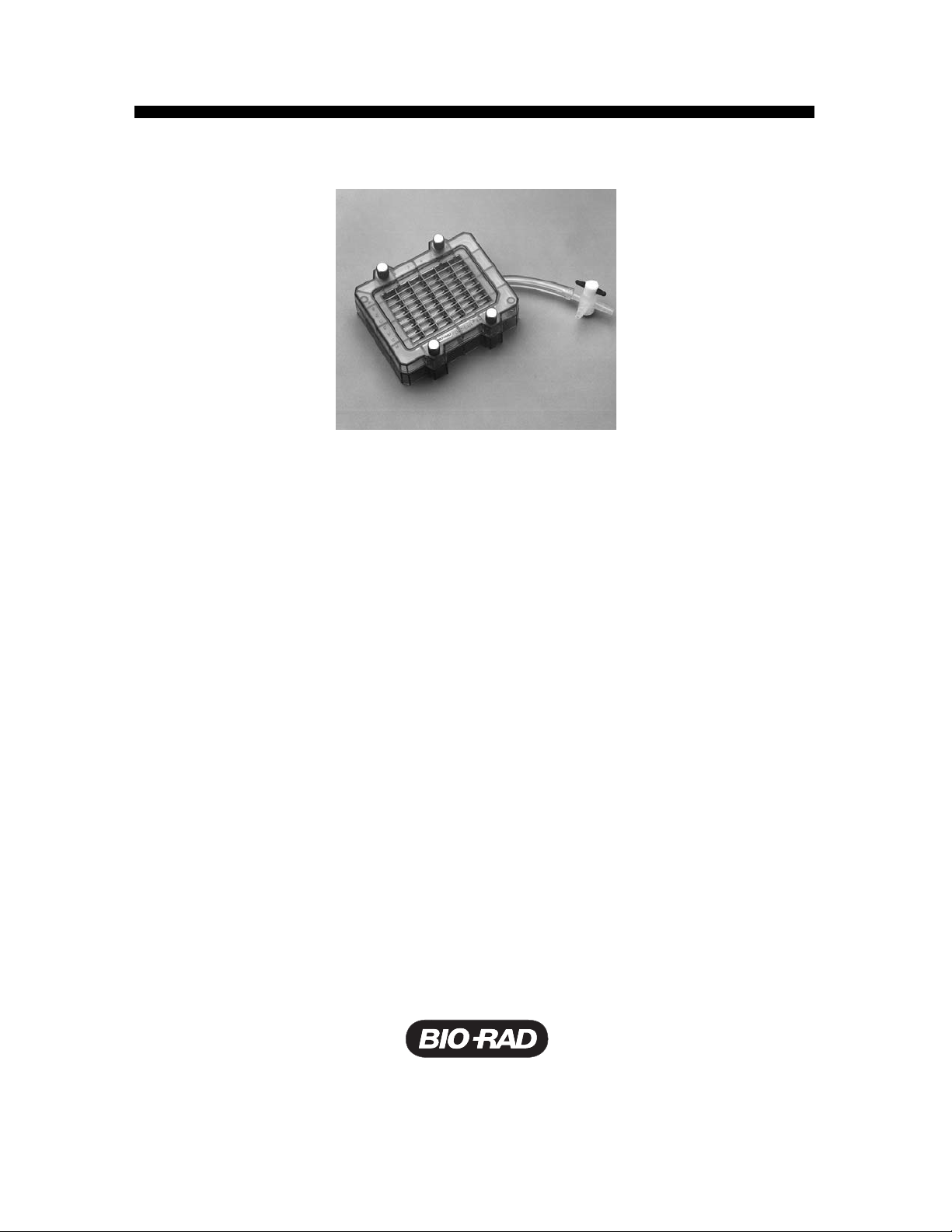
The Bio-Dot SF blotting apparatus has an evenly spaced, slot shaped sample template for easy
slot blot sample comparisons. Because the Bio-Dot SF apparatus focuses the applied samples in
a thin line instead of a circle, this slot format makes it easy to use a densitometer to quantitate
results. The Bio-Dot SF apparatus is provided as a complete unit, or as a modular addition to the
Bio-Dot microfiltration system. Conversion of the Bio-Dot SF apparatus to the
Bio-Dot blotting apparatus is accomplished by purchasing the Bio-Dot module, which provides
the 96-well sample template.
The Bio-Dot SF slot format sample template has 48 wells with dimensions of 7 mm x 0.75 mm. The
wells are arranged in 8 rows and 6 columns. Sample can be applied using a standard pipet or
with an 8-channel pipet. The material used in the construction of the Bio-Dot SF blotting
apparatus can withstand rigorous sterilization and cleanup procedures. The Bio-Dot SF
apparatus can be repeatedly autoclaved, and is resistant to many chemicals, including acids,
bases, and ethanol.
1.1 Specifications
Materials
Bio-Dot SF apparatus Molded polysulfone
Bio-Dot SF gasket Silicone rubber
Stopcock Polytetrafluoroethylene (PTFE)
Shipping weight 600 grams
Overall size 13 x 15 x 6 cm
Membrane size 12 x 9 cm sheet
Autoclaving 15 minutes at 250°F (121°C) with a 1 minute fast exhaust
Chemical compatibility The Bio-Dot SF apparatus can be used with 100% alcohol solutions
and concentrated alkali or acid solutions. It cannot be used with
aromatic or chlorinated hydrocarbons. (See Table 1)
1

Section 2
Special Handling and Features
The Bio-Dot apparatus withstands autoclave temperatures for sterilization, as well as cleaning
with alcohols, acids, and base solutions.
2.1 Autoclaving
The Tygon tubing and flow valve cannot be autoclaved. All other components of the apparatus
withstand the autoclave treatment. After repeated autoclaving (~25 cycles) the silicone rubber
gasket may need replacing. The autoclave conditions that should be used are a maximum
sterilization temperature of 250°F (121°C) for 15 minutes, followed by a 1 minute fast exhaust.
Higher temperatures or increased exposure times will significantly reduce the life of the
apparatus. Do not autoclave the unit with the thumbscrews tightened, as this may cause the unit
to warp during exposure to the elevated temperatures.
2.2 Chemical Stability
The apparatus is stable in both acid and base solutions. It is stable in all concentrations of
alcohol solutions. Both of these features allow rapid cleanup and sterilization of the apparatus
and gaskets. The unit is not compatible with polar, aromatic, or chlorinated hydrocarbons, esters,
and ketones. These solvents will cause degradation of the plastic. See Table 1 for list of chemical
stability. For color development in the apparatus, the unit is compatible with both the methanol
used in the horseradish peroxidase (HRP) color development systems and the low concentration
of DMF used to solubilize the alkaline phosphatase (AP) color development reagents. However,
high concentrations of DMF will attack the plastic. Also, the unit is completely compatible with the
low concentrations of diethyl pyrocarbonate (DEPC) used as an alternative to autoclaving for
elimination of RNase activity.
Table 1. Chemical Compatibility
Chemicals compatible with Bio-Dot SF apparatus
Hydrochloric acid Methanol
Sulfuric acid Ethanol
Phosphoric acid Butanol
Glacial acetic acid Isopropanol
Sodium hydroxide Formaldehyde
Potassium hydroxide Hydrogen peroxide
Ammonium hydroxide Ethylene glycol
Heptane 5% acetone in H
2
O
Nitric acid
Chemicals that will attack polysulfone
Ethyl acetate Toluene
Butyl acetate Benzene
Acetone Methyl ethyl ketone
Chloroform Methylene chloride
Trichloroacetic acid
2
Section 3
Bio-Dot SF Assembly
3.1 Assembly
1. Clean and dry the Bio-Dot SF apparatus and gasket prior to assembly.
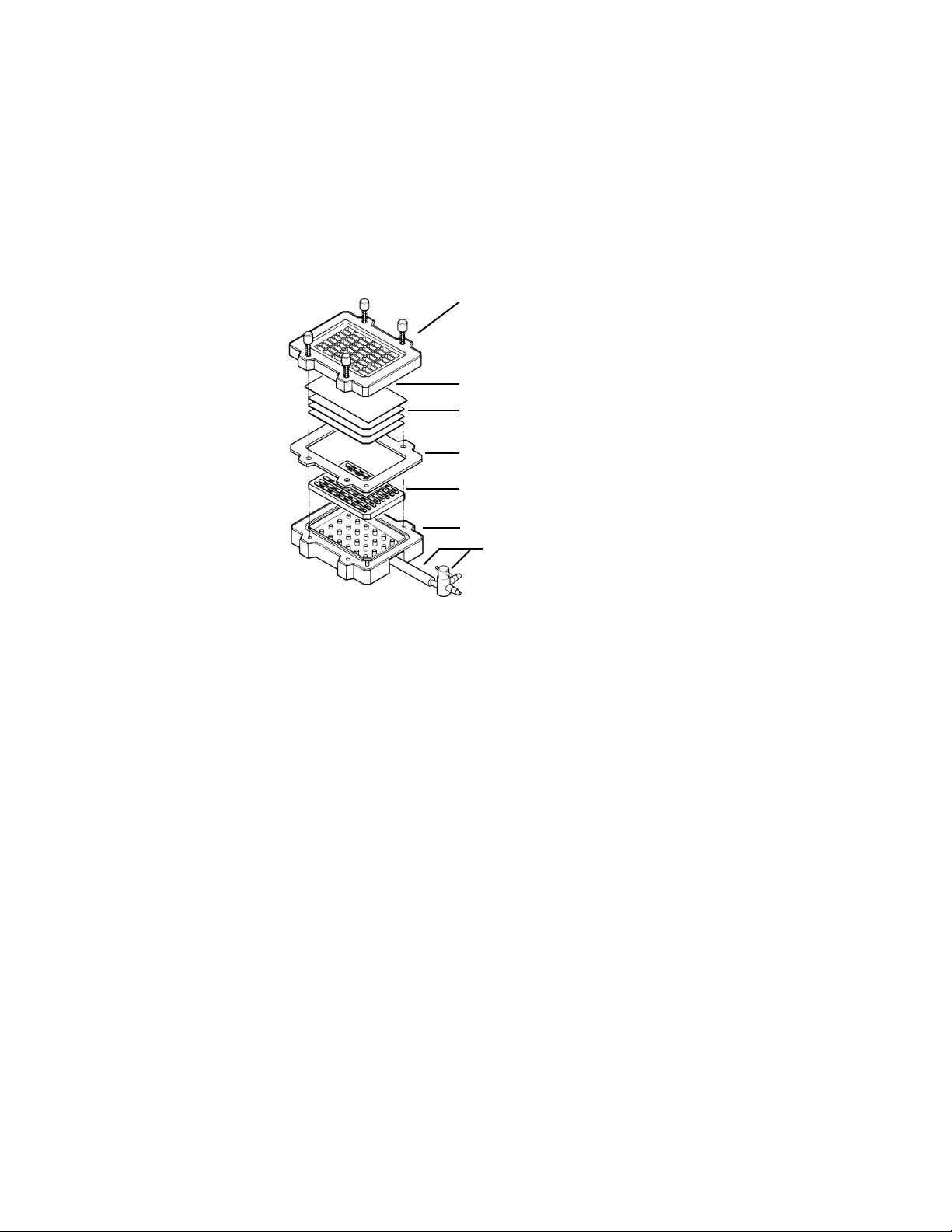
2. Place the gasket support plate into position in the vacuum manifold. (There is only one way to
slide the plate into the manifold.) Place the sealing gasket on top of the vacuum manifold.
Fig.1. Diagram of proper Bio-Dot SF apparatus assembly.
3. Moisten three sheets of Bio-Dot SF filter paper (catalog number 162–0161) in wetting
solution. Use the same solution that is used to prewet the membrane (step 4). Place the
three sheets onto the membrane support. The filter paper is precut to fit inside the sealing
gasket. Use of Bio-Dot SF filter paper ensures high quality results and eliminates the chance
of cross-well contamination.
4.
Always use forceps or wear gloves when handling membranes. Prewet the nitrocellulose or
Zeta-Probe
®
membrane by slowly sliding it at a 45° angle into wetting solution. Nitrocellulose
is wetted in 6x sodium, sodium citrate (SSC) for nucleic acid applications, and in Tris-buffered
saline (TBS) for protein binding. Zeta-Probe membrane is wetted in distilled water. See
Sections 9 and 10 for solution preparation. A 10 minute soak is recommended for complete
wetting of the membrane to ensure proper drainage of solutions. Remove the membrane from
the wetting solution. Let the excess liquid drain from the membrane. (Touching the membrane
to a sheet of filter paper is a simple method for removing excess buffer.) Lay the membrane
on the filter paper in the apparatus so it extends over the edges of the filter paper. For the best
slot blot results, use membrane sheets that have been precut to a 9 x 12 cm size (catalog
number 162–0117 for nitrocellulose, 162-0153 for Zeta-Probe membrane). In all cases, the
membrane should not extend beyond the edge of the gasket after the Bio-Dot SF apparatus is
assembled. Remove any air bubbles trapped between the membrane and the filter paper.
Note: PVDF membrane is not recommended.
3
Vacuum manifold
Membrane
Filter paper (3 sheets)
Sealing gasket
Tubing and flow valve
Sample template with attached sealing screws
Gasket support plate
5. Place the sample template on top of the membrane. The guide pins ensure that the template
will be properly aligned. Finger-tighten the four screws. When tightening the screws, use a
diagonal crossing pattern to ensure uniform application of pressure on the membrane surface
(see Figure 2).
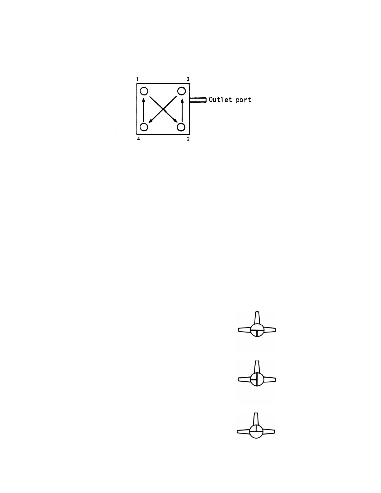
Fig. 2. Diagonal crossing pattern for tightening screws in the Bio-Dot apparatus.
6. Attach a vacuum source (house vacuum or vacuum pump) to the flow valve with a waste trap
set up and positioned between the vacuum outlet and flow valve. Turn on the vacuum and
set the 3-way valve to apply vacuum to the apparatus (flow valve setting one, Figure 3).
7. With vacuum applied, repeat the tightening process using the diagonal crossing pattern.
Tightening while vacuum is applied ensures a tight seal, preventing cross contamination
between slots. Failure to tighten screws during application of vacuum prior to starting
the assay may lead to leaking between the wells.
8. Adjust the flow valve so that the vacuum manifold is open to air (flow valve setting two,
Figure 3). Apply 100 µl to all the sample wells. Use of an 8-channel pipet and buffer
reservoirs (see Section 13 for information) will simplify the process of adding solutions to the
Bio-Dot SF apparatus. Addition of buffer is necessary to rehydrate the membrane following
the vacuum procedure in step 7. If this step is not performed prior to applying samples, assay
results will show halos or weak detection signal.
9. Gently remove the buffer from the wells by vacuum (flow valve setting three, Figure 3).
Watch the sample wells. As soon as the buffer solution drains from all the wells, adjust the
flow valve so that the unit is exposed to air and disconnect the vacuum. At this point, the unit
is ready for sample application.
Flow Valve Setting 1.
The vacuum manifold is exposed to the vacuum
source only. Use for applying vacuum to the
Bio-Dot SF apparatus.
Flow Valve Setting 2.
The manifold is exposed to air.
Use for gravity filtration procedures.
Flow Valve Setting 3.
The manifold is exposed to both air and the
vacuum. Use this setting for gentle vacuum
applications where the amount of vacuum
is regulated by putting a finger over the port
exposed to the atmosphere.
Fig. 3. Optional settings for the 3-way flow valve to obtain optimal performance from the Bio-Dot SF apparatus.
4
Vacuum
Bio-Dot
Air
Air
Vacuum
Vacuum
Bio-Dot
Bio-Dot
Air

3.2 Helpful Hints
1. During the assay, do not leave the vacuum on. This may dehydrate the membrane and may
cause halos around the wells. Apply vacuum only until solutions are removed from the
sample wells, then adjust the flow valve so that the unit is exposed to air and disconnect the
vacuum source.
2. If some sample wells are not used in a particular assay, those wells must be closed off to
insure proper vacuum to the wells in use. There are three ways to close off unused wells.
One is to apply a 3% gelatin solution to those wells. Gelatin will clog the membrane and cut
off the vacuum flow to the clogged wells. The second method is to cover the unused portion
of the apparatus with tape to prevent air from moving through those wells. The third method
is to add buffer to the empty wells at each step instead of sample or wash solutions.
3. Any particulate in samples or solutions will block the membrane and restrict flow of solutions
through the membrane. For best results, filter or centrifuge samples to remove particulate matter.
4. Check the wells after sample has been applied to insure that there are no air bubbles in the
wells. Air bubbles will prevent the sample from binding to the membrane. Air bubbles may be
removed by pipetting the liquid in the well up and down.
5. Proper positioning of the flow valve relative to the level of the apparatus is important for
proper drainage. The speed of filtration is determined by the difference in hydrostatic
pressure between the fluid in the sample wells and the opening of the flow valve which is
exposed to air. If the opening of the flow valve is above the level of the sample wells very
little drainage will occur. When the flow valve is positioned where it is at a level below the
sample wells proper drainage will occur during filtration applications.
6. The recommended sample loading volume is at least 200 µl. If sample volumes of less than
200 µl are loaded, they must be carefully applied to the center of the well. Applying the
solution on one side of the well results in unequal distribution of sample. This results in
unevenly shaped bands, leading to distorted densitometer readings.
7. The Bio-Dot SF apparatus is designed for use with an 8-channel pipet allowing eight sample
or wash solutions to be quickly and easily applied to one row at a time.
8. The best method for removing the blotted membrane from the Bio-Dot SF apparatus is to
leave the vacuum on following the wash step. With the vacuum applied, loosen the screws
and remove the sample template. Next, turn off the vacuum and remove the membrane.
5

Section 4
Protein Slot Blotting
4.1 General Recommendations
1. Solution Volume.
The liquid in the incubation vessel should be least 0.25 cm deep to ensure the membrane is
completely submerged during incubation. There should be at least 0.5 ml of reagent per cm
2
of membrane. Larger volumes may be used for convenience.
2. Handling the mMembrane.
Wear clean plastic gloves or use forceps to avoid fingerprints on the membrane.
3. Temperature.
All steps are performed at room temperature (22–25°C).
4. Incubation Vessels.
Incubation vessels may be made of plastic or glass. However, since avidin binds to
unsiliconized glass, plastic or siliconized glass vessels should be used whenever biotin-avidin
systems are employed for detection.
5. Membrane Incubation.
Agitation with a rotating shaker platform enhances incubation efficiency. If a shaker platform
is not available, hand mixing every few minutes and extended incubation periods will suffice.
6. Detection.
It is best to incubate only one membrane per vessel. Should it become necessary to use
more than one membrane per incubation vessel, calculate the solution volume based on the
membrane surface area, not the vessel size.
4.2 Immunoassay Procedure
Detailed instructions, including a comprehensive troubleshooting guide, for performing
immunoassays are given in the Immun-Blot
®
instruction manuals.
1. Assemble the Bio-Dot SF apparatus as described in Section 3.1. Prewet the membrane prior
to placing it in the apparatus. Nitrocellulose membranes are prewetted in TBS; Zeta-Probe
membrane is prewetted in distilled water (see Section 10 for solution preparation). Make sure
that all the screws have been tightened under vacuum to ensure that there will not be any
cross-well contamination.
2. Rehydrate the membrane to ensure uniform binding of the antigen. Use 100 µl TBS per well
for nitrocellulose membranes. Use 100 µl distilled water per well for the Zeta-Probe
membrane.
3. Adjust the flow valve so that the vacuum chamber is open to air (flow valve setting 2, Figure
3). Fill the appropriate wells with antigen (protein) solution, applying 50–500 µl per well. The
recommended sample loading volume is at least 200 µl. If less than 200 µl is applied, the
sample must be carefully applied to the center of the well. Applying the solution on one side
of the well results in unequal distribution of sample. This results in unevenly shaped bands,
leading to distorted densitometer readings.
Note: The solution applied should be free of insoluble particles to avoid clogging of wells.
4. Allow the entire sample to filter through the membrane by gentle vacuum. Make sure that the
flow valve is positioned at a level below the sample wells to ensure proper drainage during
filtration applications. Slow, gentle filtration is necessary for quantitative antigen binding.
Each well should be filled with the same volume of sample solution to ensure homogeneous
filtration of all sample wells.
6
 Loading...