


BIOLOGIC LP
CHROMATOGRAPHY SYSTEM
INSTRUCTION MANUAL
Catalog Numbers 731-8300 731-8301

Table of Contents
TABLE OF CONTENTS
Safety
Getting Started Quickly
Chapter 1.0 |
Introduction................................................................................................................... |
|
1 |
|
1.1 |
Overview......................................................................................................................... |
|
1 |
|
1.2 |
Features ......................................................................................................................... |
|
2 |
|
1.3 |
Unpacking....................................................................................................................... |
|
3 |
|
1.4 |
Description of System Components............................................................................... |
3 |
||
Chapter 2.0 |
Description of Components ........................................................................................ |
6 |
||
2.1 |
BioLogic LP .................................................................................................................... |
|
6 |
|
2.2 |
Proportioning Valve/Mixer Module.................................................................................. |
9 |
||
2.3 |
UV Detector.................................................................................................................... |
|
10 |
|
2.4 |
Conductivity Detector ..................................................................................................... |
11 |
||
2.5 |
Bio-Rad System Options ................................................................................................ |
12 |
||
|
2.5.1 Model 2110 Fraction Collector ............................................................................ |
12 |
||
|
2.5.2 Model 2128 Fraction Collector ............................................................................ |
13 |
||
|
2.5.3 Model 1327 Chart Recorder................................................................................ |
14 |
||
2.6 |
Non-Bio-Rad System Options ........................................................................................ |
15 |
||
|
2.6.1 |
Non-Bio-Rad Fraction Collectors......................................................................... |
15 |
|
|
2.6.2 |
Non-Bio-Rad Chart Recorders............................................................................ |
16 |
|
Chapter 3.0 |
System Connections .................................................................................................... |
17 |
||
Chapter 4.0 |
System Plumbing ......................................................................................................... |
22 |
||
4.1 |
General Guidelines for Plumbing the System ................................................................ |
22 |
||
4.2 |
Adjusting the Platen and Plumbing The Peristaltic Pump .............................................. |
24 |
||
4.3 |
Plumbing the System ..................................................................................................... |
26 |
||
4.4 |
Purging the System ........................................................................................................ |
30 |
||
Chapter 5.0 |
System Operation......................................................................................................... |
31 |
||
5.1 |
Front Panel Controls....................................................................................................... |
31 |
||
5.2 |
Manual Mode Operation................................................................................................. |
34 |
||
|
5.2.1 Manual Mode Operation of the Pump ................................................................. |
34 |
||
|
5.2.2 Manual Mode Operation of the Fraction Collector .............................................. |
38 |
||
|
5.2.3 Manual Mode Operation of the Alarms ............................................................... |
41 |
||
|
5.2.4 Manual Mode Operation of the UV Monitor ........................................................ |
42 |
||
|
5.2.5 Manual Mode Operation of the Conductivity Monitor.......................................... |
44 |
||
|
5.2.6 Manual Mode Operation of the Valves ................................................................ |
46 |
||
|
5.2.7 Manual Mode Operation of the Chart Recorder.................................................. |
48 |
||
5.3 |
Programming Mode ........................................................................................................ |
49 |
||
|
5.3.1 Programming Mode’s Main Menu ....................................................................... |
51 |
||
|
5.3.2 Creating a New Method ...................................................................................... |
53 |
||
|
5.3.3 Viewing and Editing a Method ............................................................................ |
56 |
||
|
5.3.4 |
Program Mode’s Pump Table .............................................................................. |
58 |
|
|
5.3.5 Program Mode’s Fraction Collector Table............................................................ |
62 |
||
|
|
5.3.5.1 |
Collect All Mode ................................................................................... |
64 |
|
|
5.3.5.2 |
Threshold Collection Mode................................................................... |
65 |

Table of Contents
|
|
|
5.3.5.3 |
Collection Windows Mode .................................................................... |
67 |
|
|
|
5.3.5.4 Threshold and Collection Windows Mode ............................................ |
70 |
|
|
|
5.3.6 |
Programming Mode’s Alarm Table ...................................................................... |
62 |
|
|
|
5.3.7 |
Entering Method Names ..................................................................................... |
75 |
|
|
5.4 |
Run Mode....................................................................................................................... |
|
76 |
|
|
|
5.4.1 |
Starting a Run ..................................................................................................... |
76 |
|
|
|
|
5.4.1.1 Errors Which Prevent the Start of Runs ............................................... |
78 |
|
|
|
|
5.4.1.2 Using the Delay Feature ....................................................................... |
78 |
|
|
|
5.4.2 |
Run in Progress .................................................................................................. |
79 |
|
|
|
|
5.4.2.1 Information Available during a Run ...................................................... |
80 |
|
|
|
|
5.4.2.2 |
Holding a Run....................................................................................... |
81 |
|
|
|
5.4.2.3 |
Pausing a Run...................................................................................... |
82 |
|
|
|
5.4.2.4 |
Manual Override ................................................................................... |
83 |
|
|
5.4.3 Interpreting the Chart Recorder Trace ................................................................ |
84 |
||
Chapter 6.0 |
Maintenance and Troubleshooting ............................................................................. |
85 |
|||
|
6.1 |
Cleaning and Storage..................................................................................................... |
85 |
||
|
6.2 |
Pump Calibration............................................................................................................ |
85 |
||
|
|
6.2.1 |
Nominal Calibration ............................................................................................. |
86 |
|
|
|
6.2.2 |
User Calibration .................................................................................................. |
86 |
|
|
6.3 |
Flushing/Cleaning Valves, Flow Cells, and Filters ......................................................... |
87 |
||
|
|
6.3.1 Rinsing Valves and Flow Cells............................................................................ |
87 |
||
|
|
6.3.2 Cleaning Valves and Flow Cells.......................................................................... |
87 |
||
|
|
6.3.3 Cleaning the UV Optics Module’s Filters ............................................................ |
87 |
||
|
6.4 |
Care of the Proportioning Valve and Mixer .................................................................... |
88 |
||
|
6.5 |
Replacing the Lamp in the UV Optics Module ............................................................... |
88 |
||
|
6.6 |
Troubleshooting |
.............................................................................................................. |
90 |
|
Appendix A. Specifications ............................................................................................................... |
|
92 |
|||
Appendix B. Warranty and Ordering Information ........................................................................... |
94 |
||||
LIST OF FIGURES |
|
|
|
||
1. |
BioLogic LP System ....................................................................................................................... |
|
1 |
||
2. |
Proportioning valve/Mixer module .................................................................................................. |
9 |
|||
3. |
UV Optics Module........................................................................................................................... |
|
10 |
||
4. Conductivity Flow Cell and Separate Holder.................................................................................. |
11 |
||||
5. Model 2110 Fraction Collector........................................................................................................ |
12 |
||||
6. Model 2128 Fraction Collector ....................................................................................................... |
13 |
||||
7. Model 1327 Chart Recorder ........................................................................................................... |
14 |
||||
8. Pin Assignments for BioLogic LP’s Fraction Collector and Chart Recorder Connectors ............... |
15 |
||||
9. |
Example of a BioLogic LP System ................................................................................................. |
17 |
|||
10. |
Rack Assembly |
............................................................................................................................... |
|
18 |
|
11. System Cable Connections ............................................................................................................ |
20 |
||||
12. |
Luer Fittings.................................................................................................................................... |
|
|
23 |
|
13. |
Plumbing the BioLogic ................................................................................LP Controller’s Pump |
24 |
|||
14. |
System Plumbing............................................................................................................................ |
|
27 |
||
15. |
Manual Operation ......................................................................................................of the Pump |
35 |
|||
16. |
Manual Operation ...................................................................................of the Fraction Collector |
39 |
|||
17. |
Manual Operation .....................................................................................................of the Alarms |
41 |
|||
18. |
Manual Operation ..............................................................................................of the UV Monitor |
43 |
|||
19. |
Manual Operation ...............................................................................of the Conductivity Monitor |
45 |
|||
20. |
Manual Operation .....................................................................................................of the Valves |
47 |
|||
21. |
Contents of a Method ..................................................................................................................... |
|
50 |
||

Table of Contents
22. |
List of Methods ............................................................................................................................... |
52 |
23. |
Programming a New Method.......................................................................................................... |
55 |
24. |
Programming: The Pump Table...................................................................................................... |
61 |
25. |
Programming: The Fraction Collector’s Summary ......................................................................... |
63 |
26. |
Programming: The Fraction Collector’s Collect All Mode............................................................... |
64 |
27. |
Programming: The Fraction Collector’s Threshold Mode............................................................... |
66 |
28 |
Programming: The Fraction Collector’s Windows Mode ................................................................ |
69 |
29. |
Programming: The Fraction Collector’s Threshold with Collection Windows Mode...................... |
72 |
30. |
Programming: The Alarm Table ...................................................................................................... |
74 |
31. |
Run In Progress.............................................................................................................................. |
79 |
32. |
UV Optics Module........................................................................................................................... |
89 |
LIST OF TABLES |
|
|
1. |
Description of System Components ............................................................................................... |
3 |
2. |
BioLogic LP Controller’s Front Panel Features .............................................................................. |
6 |
3. |
BioLogic LP Controller’s Rear Panel Connectors .......................................................................... |
7 |
4. |
Comparison of Flow Rate Ranges for Different Tubing IDs ........................................................... |
22 |
5. |
Front Panel Controls....................................................................................................................... |
31 |
6. |
Manual Mode Operation: Pump .................................................................................................... |
34 |
7. |
Manual Mode Operation: Fraction Collector ................................................................................. |
38 |
8. |
Manual Mode Operation: Alarms................................................................................................... |
41 |
9. |
Manual Mode Operation: UV Monitor............................................................................................ |
42 |
10. |
Manual Mode Operation: Conductivity Monitor ............................................................................. |
44 |
11. |
Manual Mode Operation: Valves ................................................................................................... |
46 |
12. |
Manual Mode Operation: Chart Recorder ..................................................................................... |
48 |
13. |
Programming Mode Operation: List of Methods ............................................................................ |
51 |
14. |
Programming Mode Operation: New Method................................................................................. |
53 |
15. |
Programming Mode Operation: Viewing and Editing a Method ..................................................... |
56 |
16. |
Programming Mode’s Pump Table ................................................................................................. |
58 |
17. |
Program Mode’s Fraction Collection Table..................................................................................... |
62 |
18. |
Program Mode’s Fraction Collection Table: Collect All.................................................................. |
64 |
19. |
Program Mode’s Fraction Collection Table: Threshold Collection................................................. |
65 |
20. |
Program Mode’s Fraction Collection Table: Collection Windows .................................................. |
67 |
21. |
Program Mode’s Fraction Collection Table: Threshold and Collection Windows.......................... |
70 |
22. |
Program Mode’s Alarm Table ......................................................................................................... |
73 |
23. |
Program Mode: Entering Method Names...................................................................................... |
75 |
24. |
Run Mode: Starting a Run............................................................................................................. |
76 |
25. |
Run Mode: Run Hold..................................................................................................................... |
81 |
26. |
Run Pause...................................................................................................................................... |
82 |

Safety
SAFETY
!
Caution/Warning
Disconnect power to any BioLogic LP component before servicing. No userserviceable parts are inside any component. Refer servicing to Bio-Rad service personnel.
The Bio-Rad BioLogic LP is certified to meet the I.E. C. 1010* safety standard for safety of laboratory equipment. Certified products are safe to use when operated in accordance with the instruction manual. This safety certification does not extend to other chromatography equipment or accessories not I.E.C. 1010 certified, even when connected to this BioLogic LP system.
This instrument is intended for laboratory use only.
The BioLogic LP conforms to the “Class A” standards for Electromagnetic Emissions, intended for laboratory equipment applications. It is possible that emissions from this product may interfere with some sensitive appliances when placed nearby or on the same circuit as those appliances. The user should be aware of this potential and take appropriate measures to avoid interference.
This instrument should not be modified or altered in any way. Alteration of this instrument will void the manufacturer’s warranty, void the I.E.C. 1010 certification, and create a potential safety hazard for the user.
Bio-Rad is not responsible for any injury or damage caused by the use of this instrument for purposes other than for which it is intended or by modifications of the instrument not performed by Bio-Rad or an authorized agent.
*I.E.C. 1010 is an internationally accepted electrical safety standard for laboratory instruments.

Getting Started
GETTING STARTED QUICKLY
This manual provides detailed discussion of the use and maintenance of the BioLogic LP system. Listed below is an overview of the steps involved in setting up and using your system.
Setting up the electrical and plumbing connections:
1.Connect system cabling, as shown in Figure 11, System Cable Connections. Note the following:
a.Chart recorder: Be sure to plug the conductivity signal banana plugs into Channel 2 of the chart recorder. (Refer to Chapter 3, step 6 for connecting the chart recorder.)
All chart recorder controls should be set to the position marked in green.
b.Fraction collector: Because this depends on the type of fraction collector you will be using, it is recommended that you read Chapter 3, steps 7 and 8 for connecting the fraction collector.
2.Select and install the pump head tubing: Select a tubing according to the flow rate that will be used for the separation. (Refer to sections 4.1 and 4.2 for plumbing the pump.)
3.Adjust the platen pressure: Read section 4.2, which discusses adjusting the platen.
4.Plumb the system: Refer to Figure 14, System Plumbing. Note the following:
a.Arrows embossed on the UV Optics module indicate flow direction.
b.The MV-6 Inject valve will conform to the diagram when the knob is turned counterclockwise.
5.Provide a drain tube for the rack tray.
Setting up the operating conditions:
1.Using the BioLogic Lp’s front panel, from the Mode keys select Manual.
a.Select your fraction collector: From the Instrument keys select Collector. From the screen display select the Model softkey.
b.Calibrate the pump: This is essential for acquiring an accurate displayed flow rate. From the Instrument keys select Pump. From the screen display select the Flow softkey. To calibrate, read section 5.2.1, Manual Mode Operation of the Pump.
c.Purge air from the system: From the screen display select the Purge softkey.
d.When the UV Monitor has warmed up (5 to 10 minutes after power on), select a sensitivity range and zero the UV Monitor: From the Instrument keys select UV. From the screen display select the Set Range or Set Max (your choice) and Zero softkeys.
Using the thumbwheel on the chart recorder, adjust the position of the Channel 1 chart recorder pen.
e.Select a sensitivity range for the Conductivity Monitor: From the Instrument keys select Cond. From the screen display select the Set Range or Min/Max (your choice) softkey.
Using the chart recorder’s thumbwheel, adjust the position of the Channel 2 chart recorder pen.
2.Program a method: From the Mode keys select Program. Refer to section 5.3 for discussion.

Getting Started
3.Make final adjustments. From the Mode keys select Manual, and from the Instrument keys select Pump. Start the pump, and with fluid flowing through the system, check the following:
a.Check the range setting for the UV Monitor, zero the UV Monitor, and position the Channel 1 pen on the chart recorder.
b.Check the range setting for the Conductivity Monitor, and position the Channel 2 pen on the chart recorder.
c.Check that a sufficient number of tubes are in the fraction collector rack.
d.Check all fittings for leaks.
e.Turn the MV-6 valve know to the left, and load the sample loop.
f.Check that the “Waste” tube is in the waste container or drain, and make sure that buffer inlet lines are submerged to the bottom of their containers.
4.Run the method: From the Mode keys select Run to start the separation. When the run starts, turn the MV-6 Inject valve knob to the right. (Refer to section 5.4.)
Introduction
1.0INTRODUCTION
1.1OVERVIEW
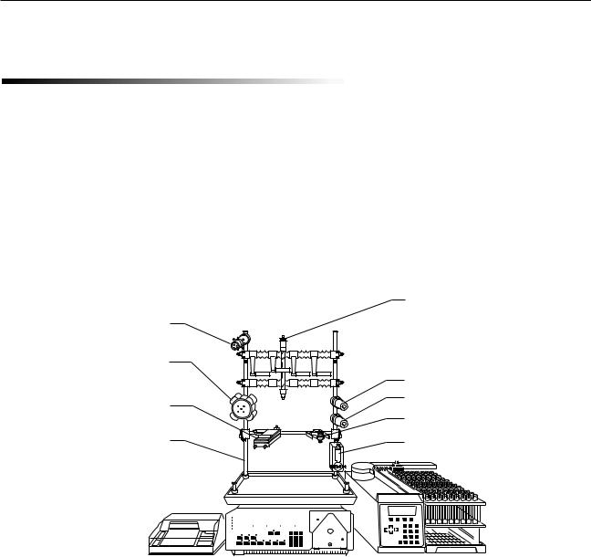
The BioLogic LP low-pressure, gradient chromatography system is designed for the purification of proteins, peptides, and other biomolecules where recovery of biological activity is of primary concern.
The BioLogic LP Controller is microprocessor controlled, with easy-to-use front panel controls and menu-dri- ven software for manual operation, system setup, method editing and run operations.
The flexible control architecture allows the seamless integration of a wide variety of configurations with other Bio-Rad and non-Bio-Rad components to meet your purification requirements.
MV-6 INJECT VALVE
SV-5 BUFFER SELECT
UV OPTICS MODULE
SYSTEM RACK
ECONO COLUMN
SV-3 DIVERTER VALVE
SV-3 BYPASS VALVE |
CONDUCTIVITY FLOW CELL |
PROPORTIONING VALVE |
AND MIXER MODULE |
|
|
|
|
|
|
|
|
|
|
|
|
|
|
|
|
|
|
|
|
|
|
|
|
|
|
|
|
|
|
|
|
|
|
|
|
|
|
|
|
|
|
|
|
|
|
|
|
|
|
|
|
|
|
|
|
|
|
|
|
|
|
|
|
|
|
|
|
|
|
|
|
|
|
|
|
|
|
|
|
|
|
|
|
|
|
|
MODEL 2128 FRACTION |
||
MODEL 1327 |
|
BIOLOGIC LP |
|||||||||||||||
CHART RECORDER |
|
CONTROLLER |
COLLECTOR |
||||||||||||||
Figure 1. BioLogic LP System
1

Introduction
1.2 FEATURES
The BioLogic LP System provides the following features:
•A space-saving modular and stackable design which minimizes the system footprint on the bench.
•Programming separation methods is menu-driven, easy and intuitive using either Time-based or Volume-based steps. Method storage capacity easily meets most laboratory requirements.
•On-screen help function.
•Single-point control of pump, UV and Conductivity monitors, chart recorder, fraction collector, valves, and timer.
•Dynamic mixing for accurate and reproducible gradient formation.
•The use of biocompatible materials throughout the flowpath to ensure maximum recovery of biological activity.
•Operation at 280nm and 254nm, with a preparative UV flow cell
•Standard conductivity cell to monitor gradient formation.
•Four Fraction Collection schemes are standard. Collection is volume-based or time-based with Collect All, Collection Windows, Threshold and Threshold + Collection Window modes. A wide range of fraction collectors may be used, including Bio-Rad’s Model 2128 and Model 2110 fraction collectors.
•Software control of diverter, column bypass, and buffer select valves.
•Sufficient tray space on the basic System Rack to hold a Model 2110 Fraction Collector or a Model 1327 Chart Recorder. Additional rack components are available to make a three-tray configuration.
•System Rack includes column supports to eliminate rack clutter.
2
Introduction
1.3 UNPACKING
When you receive the BioLogic LP System, carefully inspect the shipping containers for any damage which may have occurred in shipping. Severe damage to a container may indicate damage to its contents. If you suspect damage to the contents may have occurred, immediately file a claim with the carrier in accordance with their instructions before contacting Bio-Rad Laboratories.
!
Caution
Lift items from the bottom as you remove them from their containers!
Open each of the shipping cartons and lift the contents out of its packing. Check the contents of each box against the supplied packing list. Remove the plastic bag from each unit and inspect the unit for external damage. If any part is missing or damaged, contact Bio-Rad Laboratories immediately.
1.4 DESCRIPTION OF SYSTEM COMPONENTS
The following sections identify the key features of the BioLogic LP System and available options.
Table 1.
Description of System Components
Component |
Function |
|
|
Controller The BioLogic LP Controller consists of the following:
•System Software. Through the software’s menu-driven interface, each instrument in the system can be operated manually, or as part of a process as specified by the method you create. Software controls the Peristaltic Pump, the Mixer/Proportioning valve, the Valves, the UV/Conductivity Monitors, and peripheral instruments (such as the Model 2128 fraction collector and Model 1327 Chart Recorder) .
•Peristaltic Pump. This is a two-channel, bi-directional, variable speed, peristaltic pump, delivering flow rates from 0.05 to 40 ml/min.
•Control circuitry for the UV and Conductivity Monitors. Signal export ports for UV and Conductivity data at 1V and chart recorder control (pen up/down, start/stop).
•Control circuitry for the system valves (low pressure solenoid and buffer select valves).
•An output power connector to the UV lamp.
3
Introduction
Table 1. (continued)
Description of System Components
Component |
Function |
|
|
System Rack This is the system organizer for columns and cartridges, buffer containers, sample inject and buffer select valves, UV and Conductivity Flow Cells, and other devices used with the system. The optional BioLogic Rack Expansion kit is available to extend the rack to 3 trays.
Proportioning This combination of valve and mixer module mixes and proportions two buffers. Valve/Mixer It is designed to be rack mounted or free-standing.
Module
UV Detector This consists of the UV Optics Module and the control circuitry within the BioLogic LP Controller. The UV Optics Module includes a mercury lamp and filters for fixed wavelength UV detection at 280nm and 254nm. The flow cell has a path length of 2 mm, an internal volume of 80 l, and an illuminated volume of 3µl.
Conductivity This consists of the Conductivity Flow Cell and the control circuitry within the BioLogic LP Detector Controller. The Conductivity Flow Cell provides instantaneous, on-line readings of con-
ductance for monitoring a salt gradient and optimization of column chromatographic conditions.
Valves |
Valves for the BioLogic LP include: |
•MV-6 Inject Valve
•SV-5 Buffer Select valve
•SV-3 Diverter/Column Bypass valves
Sample Loops |
Tygon tubing sample loops are prepared by the user. |
Fraction |
Fraction collectors are controlled by the BioLogic LP Controller via the Fraction Collector |
Collector |
port. Fraction advance marks (event marks) are embedded in the UV signal sent from the |
|
Controller to a chart recorder. The following fraction collectors are supported: |
•The Model 2128 provides X-Y motion drop dispensing. The Model 2128 accommodates a wide range of tube diameters and lengths, microtiter plates, micro-tubes, and “bottle size” fractions. The Model 2128 is ideally suited for both analytical and preparative applications.
•The Model 2110 uses a stationary drop-dispensing head to collect up to 80 fractions in a carousel. The SV-3 Diverter valve is required for full operation. The Model 2110 is controlled by the BioLogic LP Controller via the Fraction Collector port.
•Generic fraction collectors may be used with the BioLogic LP as long as tube advances can be initiated by a TTL pulse (active high or active low, 100 ms duration.) The SV-3 Diverter valve is required for full operation.
Regardless of which fraction collector is chosen, fraction time/volume and collection parameters such as Collect All, Collection Windows, Threshold, and Threshold + Collection Windows are controlled from the BioLogic LP Controller.
4

Introduction
|
Table 1. (continued) |
|
Description of System Components |
|
|
Component |
Function |
|
|
Chart recorder |
Bio-Rad offers the Model 1327 Chart Recorder as a system option. This is a dual pen |
|
chart recorder for Conductivity and UV Detector readings. Stop/Start and Pen Up/Down |
|
functions are controlled by the BioLogic LP Controller. Chart speed is set at the recorder |
|
itself (the BioLogic LP Controller does not control this function). Event marks including |
|
fraction advance marks are embedded in the UV signal sent from the BioLogic LP |
|
Controller to the chart recorder. |
|
The BioLogic LP may be used with any recording instrument (such as a chart recorder, |
|
integrator, or data acquisition system) which will accept a 0 to 1 volt analog input. |
Tubing |
The following tubing is supplied with the unit: |
|
System tubing: 0.8mm ID, 1.6mm ID Tygon® tubing. |
|
Pump head tubing: 0.8mm ID, 1.6mm ID, 3.2mm ID PharMed® tubing. |
Fittings |
Luer fittings. |
|
|
PharMed and Tygon are registered trademarks of Norton Co.
5
Description of Components
2.0 DESCRIPTION OF COMPONENTS
The following sections identify the key features of each of the major system components.
2.1 BIOLOGIC LP
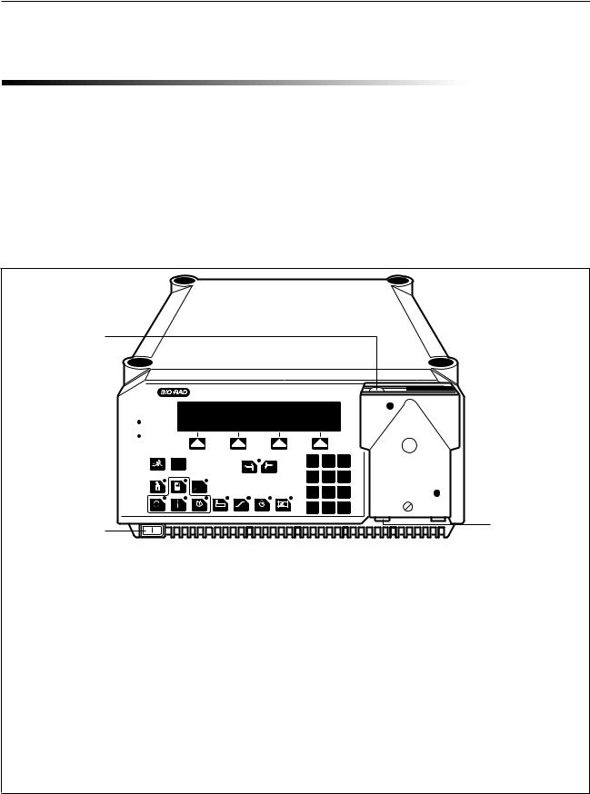
The BioLogic LP Controller is described in Table 2.
Table 2.
BioLogic LP Controller’s Front Panel Features
PLATEN ADJUST |
SCREW |
BioLogic LP
 Pump
Pump
Fraction Collector
 UV Lamp
Chart Recorder
 Alarm
Alarm
?
Mark |
Help |
|
|
Previous |
Next |
MODE
Manual Program Run
INSTR
Pump Collector Alarm UV Cond Valves Recorder
1 2 3
4 5 6
7 8 9
C 0 .
POWER ON/OFF |
PLUMBING |
|
CONNECTIONS |
||
|
Feature |
Description |
|
|
Control |
Consists of the control keys and status LEDs for monitoring and controlling the |
Panel |
system. It is designed to withstand the minor spills associated with use in a laboratory. |
|
|
Power switch |
Turns on/off the BioLogic LP Controller. |
|
|
Plumbing |
The peristaltic pump may be used with most flexible tubing having an inner diameter |
Connections |
less than or equal to 3.2 mm (1/8”) and a wall thickness of 1.0 mm or less, including |
|
PharMed, and silicone. Inlet and outlet lines attach to the ports at the bottom of the |
|
pump. These ports accept standard luer fittings. |
|
|
6
Description of Components
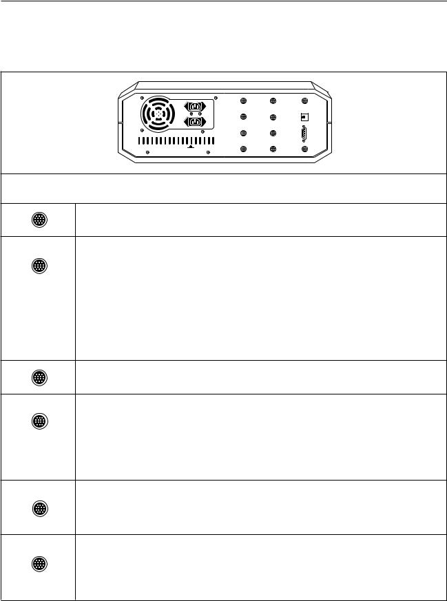
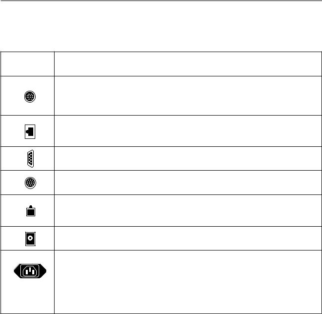
Table 3.
BioLogic LP Controller’s Rear Panel Connectors
|
|
|
|
UV |
BUFFER |
FRACTION |
|
|
|
|
|
OPTICS |
SELECTOR |
COLLECTOR |
|
|
|
|
|
UV |
BYPASS |
INSTR. |
|
|
|
|
|
CHART |
VALVE |
BUS |
|
|
|
|
|
COND |
DIVERTER |
|
|
|
|
|
|
FLOWCELL |
VALVE |
|
|
|
|
|
|
COND |
GRADIENT |
AUX |
|
|
|
|
|
CHART |
MIXER |
|
|
|
|
|
|
|
|
|
UV LAMP 12 V |
Connector |
Description |
UV Optics: For connecting the UV Optics module to the system.
UV Chart: For UV signal output to a single or dual pen chart recorder. In addition, when the Bio-Rad Model 1327 is used, chart recorder Pen Up/Down, Stop/Start commands, and event marks are sent from this port.
The Bio-Rad Model 1327 dual pen recorder needs an 8 pin mini-DIN to standard DIN cable (System Cable 2) available from Bio-Rad.
Generic chart recorders require an 8 pin mini-DIN to banana plug cable (System Cable 4) available from Bio-Rad.
The chart recorder should be set to 1V full scale.
Cond Flowcell: For connecting the Conductivity Flow Cell to the system.
Cond Chart: For conductivity signal output to a single or dual pen chart recorder.
An 8-pin mini-DIN to banana plugs cable (System Cable 4) for connection to the Model 1327 Chart Recorder is available. Connect the red line to the positive (+) terminal and the black line to the negative (–) or ground terminal of channel 2 (CH2).
The chart recorder should be set to 1V full scale.
Buffer Selector, Bypass, and Diverter Valves: These connectors are for connecting Bio-Rad’s low pressure solenoid valves (SV-5 Buffer Select and SV-3 Bypass and Diverter valves) to the system.
Proportioning valve/Mixer module: This is a combination gradient proportioning valve and mixer used for the forming of linear gradients as specified by the Method. The proportioning valve proportions, and then the dynamic mixer rapidly mixes the two solutions.
7
Description of Components
Table 3. (continued)
BioLogic LP Controller’s Rear Panel Connectors
Connector |
Description |
Fraction Collector: The BioLogic LP supports the Bio-Rad Model 2110 and Model 2128 fraction collectors, as well as other fraction collectors. This port sends “Advance” signals to the fraction collector.
Instrument bus (phone jack connector): This connector is reserved for internal BioRad use.
Test Port: This connector is reserved for internal Bio-Rad use.
Aux connector: This connector is reserved for internal Bio-Rad use.
UV Lamp: This specialized 6-pin square port provides electrical power to the mercury lamp in the UV Optics module’s lamp housing.
12 Volt: This is a 12 V DC power source designed to power optional equipment.
Power Connectors: There are two power connectors. They are keyed so that you can plug a fraction collector into one power connector and the BioLogic LP Controller’s power cord into a power strip. This arrangement means the fraction collector’s power switch can be left in the ON position. The BioLogic LP Controller’s power ON/OFF switch then turns on/off both the BioLogic LP Controller and the fraction collector.
8

Description of Components
2.2 PROPORTIONING VALVE/MIXER MODULE
This is a combination proportioning valve and mixer. The solenoid valve proportions the two solutions for the purpose of forming linear gradients, and the dynamic mixer rapidly mixes them. It can be mounted to the system rack or left free-standing.
BMIXER
A
Figure 2. Proportioning valve/Mixer module
9

Description of Components
2.3 UV DETECTOR
The UV Detector, which consists of the UV Optics Module and the control circuitry within the BioLogic LP Controller, is a single beam, fixed wavelength UV absorbance detector specifically designed for protein chromatography. The UV Optics Module can be positioned close to a column outlet, minimizing system dead volume and remixing of peaks. When connecting the UV Optics Module to the system, note the flow direction arrows on the top of the UV Optics Module’s case. It is important that the flow direction through the flow cell is correct.
 FLOW CELL
FILTER HOLDER
AND FILTERS
UNDERSIDE OF
UV OPTICS MODULE
Figure 3. UV Optics Module
The AU readings from the BioLogic LP UV detector will not correspond directly to absorbance readings from a spectrophotometer. The primary reason for this is the different path lengths; light bandwidths and other factors have an effect as well. This has no effect on the UV monitor’s ability to detect protein.
Eleven fixed UV absorbance ranges, from 5.0 to .001 Absorbance Units Full Scale (AUFS), are available. The user may choose a “custom” range using the “Set Max” function. Refer to Table 9.
The UV Optics Module consists of a low pressure mercury lamp, 280nm and 254nm filters, and a flow cell. The filters are both held by a single tray. The flow cell, which uses luer fittings, has a 2 mm path length. It has an internal volume of 80 l and an illuminated volume of 3 µl.
The UV Optics Module receives power from the BioLogic LP Controller, to which it is connected by the UV Lamp cable. The UV detector communicates with the system via the UV Optics cable, which plugs into the UV Optics connector on the back of the BioLogic LP Controller.
10

Description of Components
Figure 3 shows how the flow cell and the filters can be changed. To remove the flow cell, you will need to remove the retaining clip from the bottom of the optics module and pull the luer connectors away from their holders. Then loosen the thumbscrews and remove the flow cell. When inserting the replacement flow cell, make sure the O-ring is securely placed on the flow cell. To change the filter, loosen the filter’s thumbscrew and lift out and rotate the filter holder. The selected wavelength is indicated by the raised arrow on the bottom of the case.
WARNING: To avoid exposure to UV radiation, turn off the UV lamp when changing filters and flow cells.
2.4 CONDUCTIVITY DETECTOR
The Conductivity Detector consists of a small, portable Conductivity Flow Cell and the control circuitry which resides in the BioLogic LP Controller. This monitoring system provides a means to check equilibration conditions and the formation of a salt gradient, for example, in ion-exchange chromatography and hydrophobic interaction chromatography. This data helps in optimizing purification protocols and column cleaning procedures.
Figure 4. Conductivity Flow Cell and Separate Holder
The Conductivity Flow Cell consists of the following:
•Flow cell with Inlet/Outlet ports: For connection of the tubing, using luer fittings. The flow cell allows flow in either direction.
•Signal Cable: For connection to the back of the BioLogic LP Controller. Electrical power for the Conductivity Flow Cell is drawn off the signal cable.
The flow cell can be plumbed immediately after the UV Optics Module’s flow cell or at any other point in the flowpath. A separate holder for the Conductivity Flow Cell is mounted to the system rack. The swept volume in the cell is a nominal 2 l.
Conductivity is measured in milli-Siemens (mS). For accurate measurement, the flow cell must be calibrated. Refer to Table 10.
Nine fixed Conductivity ranges, from 500 to 0.5 mS Full Scale (mSFS), are available. The user may choose a “custom” range using the “Min/Max” function. Refer to Table 10.
11

Description of Components
2.5 BIO-RAD SYSTEM OPTIONS
Bio-Rad offers a number of system options for use with your BioLogic LP. The following instrument options are described in this section.
•Models 2110 and 2128 Fraction Collector
•Model 1327 Chart Recorder
2.5.1Model 2110 Fraction Collector
The Model 2110 collects up to 80 fractions in a motor-driven carousel. It uses standard 13 x 100 test tubes. An optional adapter is available for use with 1.5 ml microcentrifuge test tubes.
 MODEL 2110 FRACTION COLLECTOR
Figure 5. Model 2110 Fraction Collector
(Dust Cover is optional)
The Model 2110 is connected to the BioLogic LP Controller via System Cable 1. When controlled by the BioLogic LP Controller, fraction collection is by time or volume. The numeric display screen on the Model 2110 is inactive while the fraction collector is under the control of the BioLogic LP. Only the fraction collector’s Advance key is active during this time.
The SV-3 diverter valve is required by the Model 2110 when doing any collection scheme other than “Collect All.” The SV-3 diverts flow away from the fraction collector when fractions are not being collected. Collection parameters such as Collect All, Threshold, Collection Windows, and Threshold + Collection Windows become available in Program mode.
The Model 2110 is plumbed to the BioLogic LP using Tygon tubing. The Tygon tubing is inserted directly into the fraction collector’s drop former, without the need for additional fittings.
The Model 2110 fraction collector is described in detail in its separate documentation.
12
Description of Components
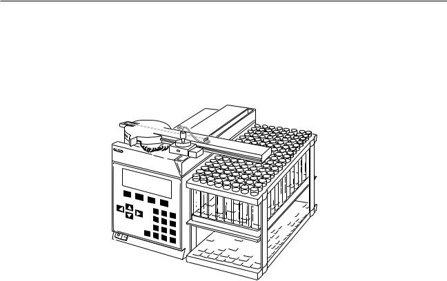
2.5.2Model 2128 Fraction Collector
The Model 2128 provides X/Y motion drop-dispensing, accommodating a wide range of tube diameters and lengths, microtiter plates, microtubes, and “bottle size” fractions. It is ideally suited for both analytical and preparative applications.
MODEL |
2128 |
|
FRA |
||
CTION |
COLLECTOR |
|
|
|
|
Threshold |
|
|
Next |
|
2 |
tube |
||
Draining |
|
|
ADV |
COLL |
|
|
||
STOP
7 |
8 |
|
|
||
4 |
5 |
|
|
||
1 |
2 |
|
HELP |
||
|
||
CE |
0 |
|
|
9 6 3 .
Figure 6. Model 2128 Fraction Collector
The Model 2128 is connected to the BioLogic LP Controller via the following cables:
•System Cable 15: This is required whenever the Model 2128 is to be controlled by the BioLogic LP Controller. It transmits the “Advance” commands. (Note: Only three of the 15 pins on the D-con- nector are used.)
•System Cable 3: This is required when the Model 2128’s arm-mounted diverter valve is used, or when no diverter valve is used. This cable transmits the “Collect/waste” commands from the BioLogic LP, which tells the fraction collector when to move the drop head to the waste trough, or when the optional arm-mounted diverter valve is to switch between collect and waste.
When connected as described above and place in its ECONO mode, the Model 2128 is controlled by the BioLogic LP Controller. Collection and tube advance is controlled by the BioLogic LP. Programming mode supports the following collection schemes: Collect All, Threshold, Collection Windows, and Threshold + Collection Windows (all with Delay volume, if desired). The Model 2128’s optional diverter valve mounts on the collector’s arm and minimizes liquid spills during fraction advances.
The Model 2128 is plumbed to the BioLogic LP Controller using Tygon tubing and either of the following fittings:
•To connect directly to the drop head, use the luer adaptor (provided with the Model 2128 Fraction Collector) to adapt the Tygon tubing from the BioLogic LP to the 1/16” tubing leading to the drop head.
•To connect to the optional arm-mounted diverter valve, use the luer adaptor (provided with the Model 2128) to adapt the Tygon tubing from the BioLogic LP to the 1/16” tubing leading to the “Common” port of the diverter valve.
This instrument is described in detail in its separate documentation.
13
Description of Components
2.5.3Model 1327 Chart Recorder
When used with the BioLogic LP, the Model 1327 Chart Recorder automatically starts when a method begins and stops when the method ends. The BioLogic LP’s Manual mode operation of the chart recorder may be used to start and stop the chart recorder.
The following cables are required to connect the Model 1327 Chart Recorder to the BioLogic LP Controller:
•System Cable 2: Through this cable, the BioLogic LP outputs the UV analog data signal, pen up/down, and Stop/Start commands to the Model 1327 chart recorder. It connects to the BioLogic LP’s UV Chart port and to the chart recorder’s DIN connector.
•System Cable 4: Through this cable, the Conductivity analog data signal is sent from the BioLogic LP to the Model 1327 Chart Recorder. The cable connects to the BioLogic LP’s Cond Chart port and to the chart recorder’s channel 2 banana plug connectors.
•Power cable and adapter: Operating power for the Model 1327 Chart Recorder is supplied via the jack next to the chart recorder’s DIN connector. (Note: The Model 1327 Chart Recorder may also be run on batteries.)
Figure 7. Model 1327 Chart Recorder
In addition, following chart recorder controls should be set:
•All chart recorder controls with a green setting should be set to their green setting.
•Paper speed dial: Select a chart speed appropriate for the separation being performed.
•Manual paper feed: Using this switch, select Paper “fast feed” to quickly advance the paper to the desired position.
•Baseline adjustment dial: These dials allow for pen position adjustment. The “zero” position of each pen is adjusted using the thumbwheel for each channel. When adjusting the pen’s zero position, make sure that the BioLogic LP instrument (UV or Conductivity Monitor) is zeroed first.
Note: The chart speed is set at the recorder itself. The BioLogic LP Controller does not control this function.
This instrument is described in detail in its separate documentation.
14
Description of Components
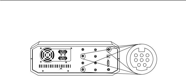
2.6 NON-BIO-RAD SYSTEM OPTIONS
Non-Bio-Rad fraction collectors and chart recorders may be used with the BioLogic LP, as discussed in the following sections.
|
|
|
|
UV |
BUFFER |
FRACTION |
|
|
|
|
|
OPTICS |
SELECTOR |
COLLECTOR |
|
|
|
|
|
UV |
BYPASS |
INSTR. |
|
|
|
|
|
CHART |
VALVE |
BUS |
|
|
|
|
|
COND |
DIVERTER |
|
|
|
|
|
|
FLOWCELL |
VALVE |
|
|
|
|
|
|
COND |
GRADIENT |
AUX |
|
|
|
|
|
CHART |
MIXER |
|
|
|
|
|
|
|
|
UV LAMP 12 V
8 7 6
5 4 3
2 1
Figure 8. Pin Assignments for BioLogic LP’s Fraction Collector and Chart Recorder Connectors
2.6.1Non-Bio-Rad Fraction Collectors
A non-Bio-Rad collector may be used with the BioLogic LP, providing its tube advance function can be initiated by a TTL signal with a duration of 100 milliseconds or greater.
Use System Cable 7 to connect a non-Bio-Rad fraction collector. Pin-outs for the BioLogic LP’s Fraction Collector port are listed below and shown in Figure 8. Pin 5 is the TTL control wire, and pin 7 is the logic ground. A wire color to pin number chart is included with System Cable 7. See the pin-out information in your collector manual.
•Pin 1: The function of this pin differs, depending on your selection in Manual mode operation of the fraction collector. (See Table 7, Manual Mode Operation: Fraction Collector for details on selecting a
fraction collector.) Manual mode offers the following selections:
Other or 2128: The BioLogic LP software allows you to select “Other” when indicating a non-Bio- Rad fraction collector. (Selecting 2128 functions similar to Other.) In this mode, this pin is normally “low” (0 volts). It goes “high” (5 volts) for 100 milliseconds when a tube change is commanded.
2110: When the Model 2110 fraction collector is selected, this pin is normally “high” (5 volts). It goes “low” (0 volts) for 100 milliseconds when a tube change is commanded.
•Pins 2 - 4: Not connected.
•Pin 5: The function of this pin differs, depending on your selection in Manual mode operation of the fraction collector. (See Table 7, Manual Mode Operation: Fraction Collector for details on selecting a
fraction collector.) Manual mode offers the following selections:
Other or 2128: When Other (or Model 2128) fraction collector is selected, this pin is normally “high” (5 volts). It goes “low” (0 volts) for 100 milliseconds when a tube change is commanded.
2110: In this mode, this pin is normally “low” (0 volts). It goes “high” (5 volts) for 100 milliseconds when a tube change is commanded.
•Pin 6: Not connected.
•Pin 7, Digital Ground: This is the “ground reference” pin for all control inputs and outputs on this connector.
•Pin 8, Event Mark In: This pin is normally high (5 volts). When an external device such as a fraction collector pulls it “low” for 100 milliseconds or more, the BioLogic LP generates an event mark on the analog output to the Chart Recorder’s channel 1.
15

Description of Components
If you are using a non-Bio-Rad fraction collector, use an SV-3 diverter valve to enable advanced features such as collection by Threshold and/or Collection Windows. If this optional valve is not used, then only Collect All is available.
2.6.2Non-Bio-Rad Chart Recorders
A non-Bio-Rad chart recorder may be used with the BioLogic LP. A mini-DIN to banana plug cable (System Cable 4) is used to connect the BioLogic LP Controller’s UV Chart port to the chart recorder. The input signal voltage should be set to 1V for both BioLogic LP UV and Conductivity signals.
The pin outs for the BioLogic LP’s UV Chart port are listed below and shown in Figure 8:
•Pin 1, Stop Paper: This pin is high (5 volts) when a method is running or when the BioLogic LP’s Manual mode is used to make the chart recorder run. When the method ends, or Manual mode is used to stop the chart recorder, the BioLogic LP pulls this pin “low” (0 volts) and the chart paper stops feeding.
•Pins 2 and 3: Not connected.
•Pin 4, Integrator (+): This pin sends an unfiltered, unscaled signal to integrators or other data acquisitions systems. An absorbance of 2 AU will cause a 1 volt signal at this pin, regardless of UV Monitor range settings. When using this output, connect the negative lead to pin 7, Analog ground.
•Pin 5, Chart Recorder (+): This pin is connected to the positive lead of the chart recorder channel 1, which displays the UV absorbance trace. This signal is 0 volts when the UV Monitor reads 0 AU, and 1 volt when the UV monitor reads “full scale”.
•Pin 6, Pen Lift: This pin is “low” (0 volts) when a method is running, or when the BioLogic LP Manual mode is used to make the chart recorder run. When the BioLogic LP allows this pin to go “high”, the pens lift from paper.
•Pin 7, Chart Recorder (–), analog/digital ground: This pin is connected to the negative lead of the chart recorder channel, which displays the UV absorbance trace. It also serves as the negative lead for the integrator signal and the negative connection for all digital signals on this connector.
•Pin 8: Not connected.
The pin outs for the BioLogic LP’s Cond Chart port are listed below and shown in Figure 8:
•Pins 1 – 4: Not connected.
•Pin 5, Chart Recorder (+): This pin is connected to the positive lead of the chart recorder’s channel 2, which displays the conductivity trace. This signal is 0 volts when the Conductivity monitor reads the programmed “minimum” conductivity value, and 1 volt when the conductivity monitor reads the programmed “maximum” value.
•Pin 6: Not connected.
•Pin 7, Chart Recorder (–), analog ground: This pin is connected to the negative lead of the chart recorder’s channel 2, which displays the conductivity trace.
•Pin 8: Not connected.
16

System Connections
3.0 SYSTEM CONNECTIONS
When setting up the system, consider the amount of bench space available, the instruments to be used with the system, and the devices to be used with the System Rack.
The BioLogic LP can be set up wherever there is available bench space and sufficient power outlets, including in 4° cold rooms or cold boxes. When used in a cold environment, it is recommended that you leave system power “ON” to minimize condensation.
All BioLogic LP systems will include as a minimum the following:
• |
Controller |
• |
Proportioning valve/Mixer module |
• System Rack (single tray configuration) |
• |
MV-6 Inject Valve |
|
• |
UV Optics Module |
• |
Fittings kit |
• |
Conductivity Flow Cell |
• |
Tubing |
Your BioLogic LP system may include components or instruments not listed above. Refer to the separate supporting documentation for each of the following types of devices:
•Bio-Rad Model 2128 or Model 2110 Fraction Collector
•Bio-Rad Model 1327 Chart Recorder
•additional valves
•instruments not purchased from Bio-Rad, such as a generic fraction collector or chart recorder
MV-6 INJECT VALVE
SV-5 BUFFER SELECT
UV OPTICS MODULE
SYSTEM RACK
ECONO COLUMN
SV-3 DIVERTER VALVE
SV-3 BYPASS VALVE |
CONDUCTIVITY FLOW CELL |
PROPORTIONING VALVE |
AND MIXER MODULE |
|
|
|
|
|
|
|
|
|
|
|
|
|
|
|
|
|
|
|
|
|
|
|
|
|
|
|
|
|
|
|
|
|
|
|
|
|
|
|
|
|
|
|
|
|
|
|
|
|
|
|
|
|
|
|
|
|
|
|
|
|
|
|
|
|
|
|
|
|
|
|
|
|
|
|
|
|
|
|
|
|
|
|
|
|
|
|
MODEL 2128 FRACTION |
||
MODEL 1327 |
|
BIOLOGIC LP |
|||||||||||||||
CHART RECORDER |
|
CONTROLLER |
COLLECTOR |
||||||||||||||
Figure 9. Example of a BioLogic LP System
17
System Connections
To set up the BioLogic LP System:
1.BioLogic LP Controller.
a.Place the BioLogic LP Controller on the bench and turn the unit so that the back side faces you.
b.Connect the power cable. Do not turn on the unit.
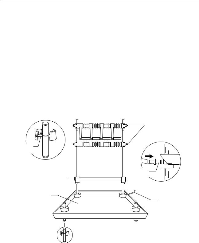
2.System Rack.
Assemble the Rack and place it on the BioLogic LP Controller, as described below.
a.Fit the tapered collars into the ringed grooves on the rods. The collars are tapered so that when they are attached to the rods and the rods are fitted into the holes at each end of the tray, the rods and collars serve as the legs of the tray. With this in mind, note the following guidelines:
•The long rods have several grooves. Attach the collars to the groove closest to the end of the rod. Attach the collars so that the taper is toward the end of the rod.
•The short rods each have only one groove. Fit the collars onto the grooves so that the collars flare out toward the farthest end of the rod. Refer to Figure 10.
b.Insert the two long rods into the holes at the back of the tray, as shown in Figure 10.
Note: The rods are inserted from underneath the tray such that they produce a firm fit in the holes.
COLUMN
CLAMPING
ARRANGEMENT
TAPERED
COLLAR
DETAIL
DRAIN
FITTING
HORIZONTAL
BAR
SIDE VIEW
TRAY
DRAIN
TUBING
Figure 10. Rack Assembly
18

System Connections
c.Insert the two short rods into the remaining holes.
d.Mount the 2-piece column clamping arrangement across the two long rods using the attached thumbscrews.
e.The horizontal bar may be positioned between the upright bars using the rod clamps (tightened by the Allen wrench) supplied with the system.
f.Place the rack into the four corner holes of the BioLogic LP Controller. Since the back of the BioLogic LP Controller is facing you, you will want the back of the rack (the side with the two long rods) also facing you.
If a hole is covered by a green cap, remove the cap.
3.Proportioning valve/Mixer module.
a.Attach the Proportioning valve/Mixer module to a suitable position on the vertical bar using the module’s rod clamp.
b.Connect the signal cable from the Proportioning valve/Mixer module to the port marked “Gradient Mixer” on the rear of the BioLogic LP Controller.
4.Buffer Select valve.
a.If you will be using the SV-5 Buffer Select valve, attach the valve to a suitable position on the horizontal bar using the valve’s rod clamp.
b.Connect the signal cable from the Buffer Select valve to the port marked “Buffer Selector” on the rear of the BioLogic LP Controller.
5.UV Optics Module and Conductivity Flow Cell.
a.Attach the UV Optics Module to a suitable position on the horizontal bar using a rod clamp to hold one of the module’s two foot-posts.
b.Connect the power cable (square connector) from the UV Optics Module lamp into the port marked “UV Lamp” on the rear of the BioLogic LP Controller.
c.Connect the UV Optics Module’s signal cable (mini-DIN connector) to the port marked “UV Optics” on the rear of the BioLogic LP Controller.
d.Connect the Conductivity Flow Cell’s combined power and signal cable (mini-DIN connector) to the port marked “Cond. Flowcell” on the rear of the BioLogic LP Controller.
e.Attach the Conductivity Flow Cell’s holder to a suitable position on the horizontal bar using the holder’s rod clamp.
f.The Conductivity Flow Cell is designed to be held in its holder, but may be placed anywhere in the fluid path as desired by the user.
19

System Connections
SYSTEM
CABLE 2
UV OPTICS
MODULE
CONTROLLER
CONDUCTIVITY
FLOW CELL
MIXER
B A
PROPORTIONING
VALVE AND
MIXER MODULE
MODEL 1327 |
SV-5 |
CHART |
BUFFER |
RECORDER |
SELECT |
|
VALVE |
SYSTEM |
|
CABLE 4 |
|
SYSTEM
CABLE 15
SYSTEM
CABLE 1
SV-3
COLUMN
BYPASS
SV-3 DIVERTER VALVE
(2110 FRACTION
COLLECTOR)
|
|
|
|
|
|
|
|
|
|
|
|
|
|
|
|
|
|
|
|
|
|
|
|
|
|
|
|
|
|
|
|
|
|
|
|
|
|
MODEL 2128 |
|
|
|
MODEL 2110 |
|||||||||||
FRACTION COLLECTOR |
OR FRACTION COLLECTOR |
||||||||||||||||
|
|
|
|
|
|
|
|
|
|
|
|
|
|
|
|
|
|
|
|
|
|
|
|
|
|
|
|
|
|
|
|
|
|
|
|
|
|
|
|
|
|
|
|
|
|
|
|
|
|
|
|
|
|
|
|
|
|
|
|
|
|
|
|
|
|
|
|
|
|
|
|
|
|
|
|
|
|
|
|
|
|
|
|
|
|
|
|
|
|
|
|
|
|
|
|
|
|
|
|
|
|
|
|
|
|
|
|
SYSTEM
CABLE 3
Figure 11. System Cable Connections
20

System Connections
6.Chart Recorder; Model 1327.
The Model 1327 chart recorder may be positioned on the rack shelf or on the bench.
a. Connect System Cable 2 between the BioLogic LP Controller and the recorder as follows:
•The mini-DIN connector is connected to the port marked “UV Chart” on the rear of the BioLogic LP Controller.
•The DIN connector is connected to the single DIN port on the side of the chart recorder.
This cable provides system control of pen up/down, event marks and paper advance, but chart speed MUST be set on the recorder faceplate itself.
b.Conductivity signals are recorded on channel 2 of the recorder using System Cable 4 as follows:
•The mini-DIN connector is connected to the port marked “Cond. Chart” on the rear of the BioLogic LP Controller.
•The banana plugs are connected to the ports marked CH 2 on the side of the recorder (red wire to +, black wire to ground | ).
c.Set both channel inputs on the recorder to 1V. Set all other switches to their position marked in green. Connect the power adapter to a wall outlet, and plug the power lead into the chart recorder.
7.Fraction Collector; Model 2110.
a.The Model 2110 fraction collector may be positioned on the rack shelf or on the bench.
b.Connect System Cable 1 between the BioLogic LP Controller’s Fraction Collector port and the fraction collector as shown in Figure 11 and described below:
•The 9-pin D connector is connected into the single D port on the rear of the Model 2110.
•Connect the power cable. (A power cable is available to connect the fraction collector to the BioLogic LP Controller, eliminating the need for a wall outlet.)
c.Position the SV-3 valve on the rack using the integral clamp.
d.Connect the SV-3 valve cable mini-DIN connector to the Diverter Valve port.
8.Fraction Collector; Model 2128.
a.Place the Model 2128 fraction collector on the bench, next to the BioLogic LP.
b.Connect System Cable 15 between the BioLogic LP Controller’s Fraction Collector port and the fraction collector as shown in Figure 11. The 15-pin D connector is connected into the single D port on the rear of the Model 2128.
c.Connect System Cable 3 between the BioLogic LP Controller’s Diverter Valve port and the fraction collector as shown in Figure 11. The mini-DIN connector is connected into the single mini-DIN port on the rear of the Model 2128.
dConnect the power cable. (A power cable is available to connect the fraction collector to the BioLogic LP Controller, eliminating the need for a wall outlet.)
When all the connections have been made, turn the units around. Plug all the power cables into an approved power-strip. The system can now be plumbed.
21

System Plumbing
4.0 SYSTEM PLUMBING
This chapter begins with discussion of plumbing practices and general guidelines, followed by a general procedure for plumbing the major system components. Later sections discuss how to plumb Bio-Rad’s low pressure valves.
4.1 GENERAL GUIDELINES FOR PLUMBING THE SYSTEM
The BioLogic LP uses the following tubing:
•System tubing: 0.8mm ID or 1.6mm ID Tygon tubing.
•Pump Tubing: 0.8mm ID, 1.6mm ID, or 3.2mm ID PharMed tubing. Refer to the following table when selecting a tubing.
Warning
Do not use pump tubing with wall thickness greater than 1.0 mm. Using tubing with a wall thickness greater than 1.0 mm can damage the pump and void the warranty.
Table 4
Comparison of Flow Rate Ranges for Different Tubing IDs
TUBING SIZE (ID/WALL)
FLOW RATE RANGE ml/hr
1.0 |
|
3.0 |
|
|
5.0 |
10 |
30 |
50 |
100 |
300 |
500 |
1000 |
|
|
|
|
|||||||||||
|
|
|
|
|
|
|
|
|
|
|
|
|
|
|
|
|
|
|
|
|
|
|
|
|
|
|
|
0.8/0.8 mm |
|
|
|
|
|
|
|
|
|
|
|
|
|
|
|
|
|
|
|
|
|
|
|
|
|
|
OPTIMAL RANGE |
|
|
|
|
|
|
|
|
|
|
|
|
|
|
|
|
|
|
|
|
|
|
|
|
|
|
||
1.6/0.8 mm |
|
|
|
|
|
|
|
|
|
|
|
|
|
|
|
|
|
|
|
|
|
|
|
|
|
|
|
|
|
|
|
|
|
|
|
|
|
|
|
|
|
|
|
|
|
|
|
|
|
|
|
|
|
MAXIMUM RANGE: |
|
|
|
|
|
|
|
|
|
|
|
|
|
|
|
|
|
|
|
|
|
|
|
|
|
|
|
||
|
|
|
|
|
|
|
|
|
|
|
|
|
|
|
|
|
|
|
|
|
|
|
|
|
|
|
|
3.2/0.8 mm |
|
|
|
|
|
|
|
|
|
|
|
|
|
|
|
|
|
|
|
|
|
|
|
|
|
|
0.8 mm: 0.05 to 1.75 ml/min |
|
|
|
|
|
|
|
|
|
|
|
|
|
|
|
|
|
|
|
|
|
|
|
|
|
|
|
1.6 mm: 0.1 to 6.5 ml/min |
|
|
|
|
|
|
|
|
|
|
|
|
|
|
|
|
|
|
|
|
|
|
|
|
||||
|
|
|
|
|
|
|
|
|
|
|
|
|
|
|
|
|
|
|
|
|
|
|
|
|
|
|
3.2 mm: 0.2 to 20.0 ml/min |
|
|
|
|
|
|
|
|
|
|
|
|
|
|
|
|
|
|
|
|
|
|
|
|
|
|
|
|
.02 |
.04 .06 .08 |
|
|
.2 |
.4 |
.6 .8 |
2 |
4 6 |
8 |
20 |
|
|
|
|
|||||||||||||
FLOW RATE RANGE ml/min
22

System Plumbing
All plumbing connections require Luer fittings. A fittings kit is included with the BioLogic LP system. The figure below shows the different Luer connectors available for use in plumbing the BioLogic LP system.
|
|
|
|
MALE LUER |
|
|
|
|
|
|
|
|
FEMALE LUER |
||
|
|
|
|
FOR SYSTEM TUBING |
|
|
|
|
|
|
|
|
|
|
|
|
|
|
|
|
|
|
|
|
|
|
|
FOR PUMP TUBING |
|||
|
|
|
|
CONNECTIONS |
|
|
|
|
|
|
|
|
|
|
|
|
|
|
|
|
|
|
|
|
|
|
|
|
|||
|
|
|
|
MALE-TO-MALE CONNECTOR |
|
|
|
|
|
|
|
|
|
|
FEMALE 'T' CONNECTOR |
|
|
|
|
|
|
|
|
|
|
|
|
|
|
||
|
|
|
|
|
|
|
|
|
|
|
|
|
|
||
|
|
|
|
|
|
|
|
|
|
|
|
|
|
|
|
|
|
|
|
|
|
|
|
|
|
|
|
|
|
|
|
Figure 12. Luer Fittings
When plumbing the system, be sure to keep tubing lengths to a minimum. Also, all fittings should be fingertight.
The procedures for plumbing the pump and all components in the BioLogic LP system are provided on the following pages.
23
 Loading...