


Table of Contents
|
|
|
Page |
Section 1 |
General Information ...................................................................... |
1 |
|
1.1 |
About This Manual .................................................................................... |
1 |
|
1.2 |
Safety Information ..................................................................................... |
1 |
|
|
1.2.1 |
Electrical Safety Information ........................................................... |
2 |
|
1.2.2 |
Laser Safety Information ................................................................ |
2 |
|
1.2.3 |
Mechanical Safety Information ....................................................... |
4 |
|
1.2.4 |
Biological Safety Information .......................................................... |
4 |
|
1.2.5 |
Blue Indicator Light ........................................................................ |
4 |
Section 2 |
Introduction ................................................................................... |
4 |
|
2.1 |
The Bio-Plex Suspension Array System and Multiplexing Technology ....... |
4 |
|
2.2 |
Description of System Components .......................................................... |
5 |
|
|
2.2.1 |
Array Reader ................................................................................. |
5 |
|
2.2.2 |
Microplate Platform ........................................................................ |
8 |
|
2.2.3 |
High-Throughput Fluidics (HTF) ..................................................... |
9 |
|
2.2.4 |
Computer and Monitor.................................................................. |
10 |
|
2.2.5 Maintenance, Calibration, and Validation Plate ............................ |
10 |
|
|
2.2.6 |
Bio-Plex Reservoir ....................................................................... |
10 |
2.3 |
Recommended Additional Equipment Not Provided ................................ |
11 |
|
2.4 |
Bio-Plex Assays ...................................................................................... |
11 |
|
Section 3 |
Installation ................................................................................... |
11 |
|
3.1 |
Unpacking ............................................................................................... |
11 |
|
3.2 |
System Location ...................................................................................... |
11 |
|
3.3 |
Microplate Platform Setup ....................................................................... |
12 |
|
3.4 |
Array Reader Setup ................................................................................. |
12 |
|
3.5 |
Connecting the Sheath Fluid and Waste Containers ................................ |
14 |
|
3.6 |
Computer and Monitor Connections ........................................................ |
15 |
|
3.7 |
Software Installation ................................................................................ |
15 |
|
|
3.7.1 |
System Software Loading ............................................................ |
15 |
|
3.7.2 |
Communication Ports .................................................................. |
16 |
3.8 |
Installing or Changing the Sample Needle ............................................... |
16 |
|
|
3.8.1 Installing/Changing the Long Sample Needle ............................... |
16 |
|
|
3.8.2 Adjusting Sample Needle Height ................................................. |
17 |
|
3.9 |
Initial System Priming............................................................................... |
19 |
|
3.10 |
Resetting Instrument Pressure Settings .................................................. |
20 |
|
3.11 |
High-Throughput Fluidics (HTF) Setup .................................................... |
20 |
|
3.12 |
Vacuum Manifold Setup .......................................................................... |
24 |
|
|
3.12.1 System Setup .............................................................................. |
24 |
|
|
3.12.2 Validation of Vacuum Pressure .................................................... |
25 |
|
3.13 |
Performing System Validation ................................................................. |
26 |
|
Section 4 Care and Maintenance ................................................................ |
27 |
||
Section 5 |
Troubleshooting Guide ............................................................... |
30 |
|
5.1 |
Troubleshooting Guide for Bio-Plex 200 System ..................................... |
30 |
|
5.2 |
Troubleshooting Guide for Vacuum Manifold ........................................... |
35 |
|
5.3 |
Technical Support ................................................................................... |
36 |
|
Section 6 Bio-Plex 200 System Specifications .......................................... |
36 |
||
Section 7 |
Warranty Statement .................................................................... |
38 |
|
Section 8 |
Ordering Information – System Accessories ............................ |
39 |
|
Section 9 |
Decontamination Information .................................................... |
41 |
|
Section 10 |
Legal Notices .............................................................................. |
42 |
|

Section 1
General Information
1.1 About This Manual
A Bio-Rad service engineer will install the Bio-Plex® 200 system. However, the procedure is provided herein as a reference, in addition to instructions for maintaining your Bio-Plex 200 system. This manual uses certain conventions to facilitate understanding of the text material and to assist operators in using the Bio-Plex 200 system.
Conventions
Left and right sides of the system components are as viewed from the front (operator’s position) unless otherwise stated.
Notes, Cautions, and Warnings
Notes, cautions, and warnings are used to highlight certain operating procedures and recommendations.
A note indicates a special procedure, an exception to normal operation, or something else of specific interest to the reader. Notes are preceded by the word "Note" in italics.
The following symbols describe the warning and cautions used in the operation of this instrument.
Warning Symbols
General Warning |
Puncture Hazard |
Pinch Point Hazard |
(See manual for specific areas where these symbols may be found.)
1.2 Safety Information
Your safety and the safety of others are very important to us. To help you make informed decisions about safety, we have provided comprehensive operating procedures and safety information in this manual and on labels affixed to instrumentation. This information will alert you to any potential hazards. Please review the safety information contained in this manual.
The user should be present during operation of the Bio-Plex 200 system. This system contains electrical, mechanical, and laser components that, if handled improperly, are potentially harmful. In addition, biological hazards may be present during system operation. Therefore, Bio-Rad recommends that all Bio-Plex 200 system users become familiar with the specific safety advisory below, in addition to adherence to standard laboratory safety practices. The protection provided by the equipment may be impaired or the warranty voided if the equipment is used in a manner not specified by Bio-Rad Laboratories, Inc.
1 |
www.bio-rad.com/bioplex/ |

1.2.1 Electrical Safety Information
Warning: This instrument must be connected to an approved power source.
Warning: Do not perform any maintenance or cleaning of the electrical components (except for fuses) of this instrument.
Warning: This system contains fluidics. In the event of a fluid leak, turn off all power to the system and disconnect all power cords. Contact Bio-Rad Technical Support for further information.
Note: Waste levels must be manually monitored. Do not allow the waste container to overflow! Empty the waste container each time sheath fluid is filled. The waste container should not be placed on top of the Bio-Plex array reader.
1.2.2 Laser Safety Information
Caution: Use of controls or adjustments or performance of procedures other than those specified herein may result in hazardous laser radiation exposure.
This instrument and its accessories are certified according to US FDA 21 CFR 1040.10 of the Center for Devices, Radiological Health (CDRH) as a class 1 laser device. The two lasers contained within the array reader produce diode laser energy of up to 10 mW at 532 nm (reporter laser) and 635 nm (classification laser).
The United States and international regulations require the following warnings to appear on the instrument during operation and maintenance. These labels appear on the back panel of the instrument:
www.bio-rad.com/bioplex/ |
2 |

Caution: Removal of the array reader cover is intended for trained service personnel only. Do not attempt to operate the instrument with the cover removed. When routine maintenance is performed, power to the instrument must be OFF and the power cord must be disconnected.
This label appears on the back of the instrument:
All laser apertures are located within the instrument and are contained within a protective housing. This label appears next to the laser apertures, located inside the optics enclosure, enclosed in the instrument:
3 |
www.bio-rad.com/bioplex/ |

1.2.3 Mechanical Safety Information
Caution: During operation, this system contains exposed, moving parts. Risk of personal injury is present. Keep hands and fingers away from the sample probe and the syringe arm, as well as the microplate platform during operation.
Note: Access doors must be closed while operating the Bio-Plex 200 system.
1.2.4 Biological Safety Information
Warning: All human and animal samples may contain hazardous infectious agents. Follow appropriate biosafety procedures when handling these products and any containers.
Observe all local, state, and federal biohazard handling regulations when disposing of biohazardous waste material.
1.2.5 Blue Indicator Light
Note: The blue lights above the sample arm, on the microplate platform, and on the high-throughput fluidics (HTF) system indicate the on/off status of the respective system components. The blue light emitting diode (LED) does not emit laser light or light in the UV spectrum.
Section 2
Introduction
2.1 The Bio-Plex® Suspension Array System and Multiplexing Technology
The Bio-Plex suspension array system is a unique and complete system comprising a 96-well fluorescent microplate reader, Bio-Plex Manager™ software, validation and calibration kits, and assays. The system is designed, manufactured, and tested as a fully integrated system to ensure accurate and reproducible assay results that are comparable across different laboratories. Centered around a flow-based dual laser detector with real-time digital signal processing, the Bio-Plex 200 system is able to distinguish up to 100 different families of color-coded, monodisperse polystyrene beads, each bearing a different homogeneous capture assay (but all using the same signal molecule) in a single 50 μl sample. This high degree of multiplexing dramatically increases the amount of useful information from rare or volume-limited samples, such as mouse and rat serum, and allows you to investigate analyte and biomarker interrelationships that would not have been possible with traditional analysis systems. A microplate platform allows the automated analysis of 96-well plates. The throughput of samples using this system will allow analysis of more than 9,600 assay points in 30 min in a 96-well plate.
The Bio-Plex suspension array system uses up to 100 color-coded bead sets, each of which may be conjugated with a unique specific reactant. Each reactant is specific for a different target analyte. Reactants can include enzyme substrates, receptors, antigens, and antibodies to create, for example, a capture sandwich immunoassay. To perform a multiplex assay, sample and reporter molecules are allowed to react with the conjugated bead mixture in microplate wells. The flow-based Bio-Plex 200 system identifies each specific reaction based on bead color and quantitates it. The magnitude of the reaction is measured using fluorescently labeled reporter molecules also specific for each target analyte. Bio-Plex Manager software automates data analysis and generation of detailed summary reports. With the Bio-Plex suspension array system you can:
•Simultaneously quantitate up to 100 analytes per sample from culture media and serum
•Automatically analyze up to 96 samples in 30 min
•Instantly customize your assay by mixing Bio-Plex assays, or create your own assays
•Dramatically increase the amount of useful data obtained from a single sample
For more specific or updated information, visit us at www.bio-rad.com/bio-plex/
www.bio-rad.com/bioplex/ |
4 |
2.2 Description of System Components
The Bio-Plex 200 system is comprised of the following components:
•Array reader — combines 2 lasers, fluidics, and real-time digital signal processing to distinguish up to 100 different color-coded different color-coded bead sets, each representing a different assay
•Microplate platform — automates the reading of 96-well plates, yielding up to 9,600 data points in ~ 35 min
•PC and monitor — controls the Bio-Plex suspension array system via Bio-Plex Manager software
•MCV (maintenance, calibration, and validation) plate IV — automates the maintenance, calibration, and validation functions of the array reader
•Bio-Plex reservoir — allows maintenance functions to be seamlessly run before and after a protocol resulting in improved walkaway capability
•Calibration kit — contains beads to standardize daily signal output and ensure unit-to-unit reproducibility of the reader
•Validation kit — contains beads to validate the operational specifications of the reader, including accuracy, linearity, dynamic range, slope, fluidics, and optical alignment
•Optional HTF — delivers up to 20 L of sheath fluid without user intervention
•Sheath fluid cube — contains 20 L of sheath fluid (1x) for the array reader
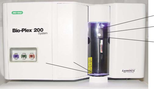
2.2.1 Array Reader
The array reader (Figure 1) is a compact flow analysis unit integrating a dual laser detection system, optics, fluidics, and advanced digital signal processing. When used with the microplate platform, the array reader facilitates the simultaneous analysis of up to 100 different analytes from a single sample. The features of the array reader are outlined in Table 1.
|
|
|
|
Cheminert fitting |
|
|
|
|
Sample arm |
Fluid connection |
|
|
|
Needle height adjustment |
(side of reader) |
|
|
|
|
|
|
|
|
thumbscrew |
|
|
|
|
Sample needle |
|
|
|
|
|
|
|
|
|
Access doors |
|
|
|
Fig. 1. Array reader – front and side panel features.
5 |
www.bio-rad.com/bioplex/ |
Table 1. Array Reader Front and Side Panel Features.
Feature |
Description |
Sample arm |
The sample arm transports the sample from the 96-well |
|
microtiter plate in the microplate platform to the cuvette. |
|
Upon operation, the carriage drops automatically to the |
|
microtiter plate for sample retrieval. |
Sample needle |
A stainless-steel sample needle acquires sample from |
|
the 96-well plate in the microplate platform. |
Cheminert fitting |
Covered by the sample arm cover, this fitting may be |
|
disconnected to allow replacement of the sample needle |
|
if necessary. |
Access doors |
There are two access doors on the face of the array |
|
reader. The centermost door allows access to the |
|
syringe. The left door provides access to the sheath filter. |
Air, waste fluid, |
Located on the side of the instrument, these connectors |
and sheath fluid |
couple directly to the sheath and waste fluid connectors. |
connectors |
The air connector is green, the sheath connector is blue, |
|
and the waste fluid connector is orange. |
The rear panel features of the array reader are shown in Figure 2 and described in Table 2.
Air filter and access door
Communication port P1
Communication port P2
Power connector
Fig. 2. Array reader – rear panel features.
www.bio-rad.com/bioplex/ |
6 |

Table 2. Array Reader Rear Panel Features.
Feature |
Description |
Communications |
The DB9-PIN connector is used to connect the array |
port P1 |
reader to the computer. |
Communications |
The DB9-PIN connector is used to connect the array |
port P2 |
reader to an HTF. |
Air filter and |
A replaceable filter cleans the air used to pressurize |
access door |
sheath fluid. This filter is enclosed behind an access |
|
door. Refer to the Care and Maintenance section |
|
(page 27) for routine maintenance procedures. |
Ventilation filter |
Located on the bottom of the instrument, the |
(not shown) |
ventilation filter must be checked and cleaned as |
|
necessary. Refer to the Care and Maintenance section |
|
(page 28) for cleaning procedures. |
Power connector |
Contains the instrument on/off switch and fuses. |
|
Refer to the Care and Maintenance section (Section 4, |
|
page 29) for fuse replacement instructions. |
Sheath filter
Syringe
Fig. 3A. Sheath filter internal fluidics features. Fig. 3B. Internal fluidics features.
Table 3. Array Reader Internal Fluidics Features.
Feature |
Description |
Syringe |
Located behind the center door immediately to the left |
|
of the sample needle assembly, the syringe delivers |
|
sample from the 96-well microplate to the cuvette via |
|
an intermediate sample loop. |
Sample loop |
The sample is drawn into the sample loop by the |
(not shown) |
syringe pump and injected into the cuvette for analysis. |
Sheath filter |
This filter removes particles greater than 5 µm in |
|
diameter from the sheath fluid. Refer to the Care and |
|
Maintenance section (page 28) for routine maintenance |
|
instructions. |
7 |
www.bio-rad.com/bioplex/ |

2.2.2 Microplate Platform
The microplate platform (Figures 4 and 5) allows the automated processing of samples from a 96-well microplate. The features of the microplate platform are outlined in Table 4.
Blue shipping pin
Access door
Fig. 4. Microplate platform – front view.
Power connector |
Communications port |
Fig. 5. Microplate platform – back panel view.
Table 4. Microplate Platform Features.
Feature |
Description |
Access door |
This door provides access to the assay plate holder. |
|
Operation of the access door is controlled through |
|
the system software. |
Blue shipping pin |
A temporary fitting for shipping purposes. |
Communications port |
A DB9-PIN connector used to connect the microplate |
|
platform to the computer. |
Power connector |
Contains the instrument on/off switch and fuses. |
|
Refer to the Care and Maintenance section (page 29) |
|
for fuse replacement instructions. |
www.bio-rad.com/bioplexsystem/ |
8 |

2.2.3 High-Throughput Fluidics (HTF)
The Bio-Plex HTF (high-throughput fluidics) is designed to automate the introduction of sheath fluid into the array reader (Figures 6 and 7). With the HTF, you can run samples continuously without the need to replenish the sheath supply. The HTF automatically draws sheath fluid from a nonpressurized bulk container to constantly maintain a reservoir of pressurized sheath fluid. A single 20 L container provides enough sheath fluid for 48 hr or more of normal operation, or forty 96-well assay plates. The features of the HTF are outlined in Table 5.
Power indicator light
Fault indicator light
Prime button
Regulator adjustment screw
Air in port
Sheath out port
Sheath in port
Fig. 6. HTF – front view.
Communications port P2 (to HTF)
Communications port P1
Power connector
Fig. 7. HTF – rear panel view with connection to Bio-Plex 200 system.
Table 5. HTF Features.
Feature |
Description |
Power indicator light |
Indicates that the power to the system is on |
Fault indicator light |
Indicates when a fault has occurred with the system |
Prime button |
Primes the HTF |
Regulator adjustment screw |
Adjusts the sheath pressure of the array reader |
Air in port |
Port where air line from array reader is connected |
Sheath out port |
Port where sheath line from array reader is connected |
Sheath in port |
Port where sheath supply (sheath cube) is connected to |
|
the HTF |
Communications port |
A DB9-PIN connector used to connect the HTF to the |
|
reader |
9 |
www.bio-rad.com/bioplex/ |
|

2.2.4 Computer and Monitor
The Bio-Plex 200 system may be supplied with a computer. If so, please transfer the computer’s registration to your company’s name following unpacking.
2.2.5 Maintenance, Calibration, and Validation Plate
The Bio-Plex maintenance, calibration, and validation (MCV) plate IV (Figure 8) is a specially designed accessory to facilitate automated system startup, calibration and shut-down procedures, as well as validation routines used to qualify the performance of the array reader. It is designed for use with the Bio-Plex validation kit to verify the performance of the instrument. Sized like a 96-well microplate, it contains labeled wells for bead solutions as well as larger reservoirs for system wash and sterilization solutions.
Fig. 8. Maintenance, calibration, and validation (MCV) plate IV.
2.2.6 Bio-Plex Reservoir
The Bio-Plex Reservoir (Figure 9) is a specially designed accessory that enables “walk away” capabilities and greatly simplifies maintenance functions. The reservoir is used in conjunction with a protocol that allows the user to perform maintenance functions either before starting a run or at the completion of a run without manual intervention.
Fig. 9. Bio-Plex reservoir.
www.bio-rad.com/bioplex/ |
10 |
 Loading...