


C1000 Touch™ Thermal Cycler
Instruction Manual
Catalog #184-1100 #185-1138 #185-1148 #185-1196 #185-1197
C1000 TouchTM Thermal Cycler Manual
Copyright ©2011 Bio-Rad Laboratories, Inc. Reproduction in any form, either print or electronic, is prohibited without written permission of Bio-Rad Laboratories, Inc.
Gmail is a trademark of Google, Inc.
LICENSE NOTICE TO PURCHASER
This base unit, Serial No. __________, in combination with its immediately attached Bio-Rad sample block module(s), constitutes a thermal cycler whose purchase conveys a limited non-transferable immunity from suit for the purchaser’s own internal research and development and for use in human in vitro diagnostics and all other applied fields under U.S. Patent No. 5,475,610 (claims 1, 44, 158, 160-163 and 167 only), or corresponding claims in its non-U.S. counterpart, owned by Applera Corporation. No right is conveyed expressly, by implication, or by estoppel under any other patent claim, such as claims to apparatus, reagents, kits, or methods such as 5´ nuclease methods. Further information on purchasing licenses may be obtained by contacting the Director of Licensing, Applied Biosystems, 850 Lincoln Centre Drive, Foster City, California 94404, USA.
This C1000 TouchTM thermal cycler base unit, when combined with a CFX96TM or CFX384TM detection module, constitutes a real-time thermal cycler authorized for use in research, human in vitro diagnostics, and all applied fields except veterinary in vitro diagnostics. No rights are conveyed expressly, by implication or estoppel to any patents on real-time methods, including but not limited to 5´ nuclease assays, or to any patent claiming a reagent or kit. For further information on purchasing license rights, contact the Director of Licensing at Applied Biosystems, 850 Lincoln Centre Drive, Foster City, California, 94404, USA.
These products are covered by one or more of the following U.S. patents or their foreign counterparts owned by Eppendorf AG: US Patent Nos. 6,767, 512 and 7,074,367.
i
C1000 TouchTM Thermal Cycler Manual
Bio-Rad Laboratories Resources
Bio-Rad provides many resources for scientists. The Bio-Rad website contains useful information for running PCR and real-time PCR experiments:
•www.bio-rad.com
This site includes links to technical notes, manuals, product information, and technical support. This site also provides many technical resources on a wide variety of methods and applications related to PCR, real-time PCR, and gene expression.
Table 1 lists Bio-Rad resources and how to locate what you need.
Table 1. Bio-Rad resources.
Resource |
How to Contact |
|
|
Local Bio-Rad Laboratories |
Find local information and contacts on the Bio-Rad |
representatives |
Laboratories web site (www.bio-rad.com). Find the |
|
nearest international office listed on the back of this |
|
manual. |
|
|
Technical notes and literature |
Find technical information on the Bio-Rad Laboratories |
|
website (www.bio-rad.com). Type a term in the Search |
|
box and select Documents to find links to technical notes, |
|
manuals, and other literature. |
|
|
Technical specialists |
To find local technical support on the phone, contact your |
|
nearest Bio-Rad Laboratories office. For technical support |
|
in the United States and Canada, call 1-800-424-6723 |
|
(toll-free phone), and select the technical support option. |
|
|
Warranty
The C1000 TouchTM thermal cycler and associated accessories are covered by a standard Bio-Rad warranty. Contact your local Bio-Rad Laboratories office for the details of the warranty.
Writing Conventions Used in This Manual
This manual provides instructions on how to safely set up and operate the C1000 Touch thermal cycler and uses the writing conventions shown in Table 2 to quickly provide relevant information.
Table 2. Writing conventions.
Convention |
Meaning |
|
|
TIP: |
Provides helpful instructions, including information explained in |
|
further detail elsewhere in this manual. |
|
|
NOTE: |
Provides important information, including information explained in |
|
further detail elsewhere in this manual. |
|
|
ii

C1000 TouchTM Thermal Cycler Manual
Table 2. Writing conventions. (Continued)
Convention |
Meaning |
|
|
WARNING! |
Explains crucial information about a topic that may lead to injury |
|
to the user, instrument damage, or data loss. |
|
|
Touch X |
Touch X using your finger. For example, touch the NEW button |
|
means use your finger to touch the NEW button on the screen. |
|
|
Touch X > Y |
From menu X, touch Y. For example, touch MAIN > RUN means |
|
touch the RUN button in the MAIN menu. |
Safety and Regulatory Compliance
The C1000 Touch thermal cycler heats and cools very quickly during operation. We strongly recommend that you follow the safety specifications listed in this section and throughout this manual.
Use only Bio-Rad USB cable (catalog #184-8000) when using any 1000-series cycler.
Safety Warning Labels
Warning labels posted on the instrument and in this manual warn you about sources of injury or harm. Refer to Table 3 to review the meaning of each safety warning label.
Table 3. Instrument safety warning labels
Icon Meaning
CAUTION: Risk of danger! This symbol identifies components that pose a risk of personal injury or damage to the instrument if improperly handled. Wherever this symbol appears, consult the manual for further information before proceeding.
CAUTION: Risk of electrical shock! This symbol identifies components that pose a risk of electrical shock if improperly handled.
CAUTION: Hot surface! This symbol identifies components that pose a risk of personal injury due to excessive heat if improperly handled.
iii

C1000 TouchTM Thermal Cycler Manual
Instrument Safety Warnings
The following warning labels display on the instrument, and refer directly to the safe use of this C1000 Touch thermal cycler (Table 4).
Table 4. Instrument safety warning labels.
Icon Meaning
Warning about risk of harm to body or equipment.
Operating the C1000 Touch instrument before reading this manual can constitute a personal injury hazard. Only qualified laboratory personnel should operate this instrument.
Warning about risk of harm to body or equipment from electrical shock.
Do not attempt to repair or remove the outer case of this thermal cycler base, power supply, heat pump, or other accessories. If you open these instruments, you put yourself at risk for electrical shock and void your warranty. All repairs must be done by an authorized repair service.
Never remove the outer case of a thermal cycler base. This may cause you to receive an electrical shock.
This thermal cycler uses neutral fusing, which means that live power could still be exposed inside the instrument even when the fuse is blown or removed.
Warning about risk of burning.
A thermal cycler generates enough heat to cause serious burns. Wear safety goggles or other eye protection at all times during operation. Always allow the sample block to return to idle temperature before opening the lid and removing samples. Always allow maximum clearance to avoid accidental skin burns.
Warning about risk of explosion.
The sample blocks can become hot enough during the course of normal operation to cause liquids to boil and explode.
Safety and Regulatory Compliance
This instrument has been designed to be safely operated under the environmental conditions listed in Table 5.
Table 5. Conditions for safe use.
Usage Aspect |
Conditions for Safe Use |
|
|
Rated input power |
100-240 VAC, 50-60 Hz, 850 W Max |
|
|
Overvoltage category |
II |
|
|
Fuses |
10 A, 250 V, 5 x 20 mm, fast blow (qty. 2) |
|
|
Environment |
Indoor use only |
|
|
Temperature |
15-31oC |
Relative humidity |
Up to 80% (noncondensing) |
|
|
Altitude |
Up to 2,000 meters above sea level |
|
|
Pollution degree |
2 |
|
|
SAFETY COMPLIANCE
This instrument has been tested and found to be in compliance with all applicable requirements of the following safety and electromagnetic standards:
iv
C1000 TouchTM Thermal Cycler Manual
•IEC 61010-1:2001 Safety Requirements for Electrical Equipment for Measurement, Control, and Laboratory Use, Part 1: General Requirements
•IEC 61010-2-010:2003 Safety Requirements for Electrical Equipment for Measurement, Control, and Laboratory use, Part 2-010: Particular Requirements for Laboratory Equipment for the Heating of Materials
•IEC 61010-2-081:2001+A1:2003 Safety Requirements for Electrical Equipment for Measurement, Control, and Laboratory use, Part 2-081: Particular Requirements for automatic and semi-automatic laboratory equipment for analysis and other purposes
•CAN/CSA-C22.2 NO. 61010-1-04 Safety Requirements for Electrical Equipment for Measurement, Control, and Laboratory Use, Part 1: General Requirements
•CAN/CSA-C22.2 NO. 61010-2-010-04 Safety Requirements for Electrical Equipment for Measurement, Control, and Laboratory use, Part 2-010: Particular Requirements for Laboratory Equipment for the Heating of Materials
•CAN/CSA-C22.2 NO. 61010-2-081-04 Safety Requirements for Electrical Equipment for Measurement, Control, and Laboratory use, Part 2-081: Particular Requirements for automatic and semi-automatic laboratory equipment for analysis and other purposes
•EN 61010-1:2001 Safety Requirements for Electrical Equipment for Measurement, Control, and Laboratory Use, Part 1: General Requirements
•EN 61010-2-010:2003 Safety Requirements for Electrical Equipment for Measurement, Control, and Laboratory use, Part 2-010: Particular Requirements for Laboratory Equipment for the Heating of Materials
•EN 61010-2-081:2002+A1:2003 Safety Requirements for Electrical Equipment for Measurement, Control, and Laboratory use, Part 2-081: Particular Requirements for automatic and semi-automatic laboratory equipment for analysis and other purposes
•UL 61010-1:2004(R2008) Safety Requirements for Electrical Equipment for Measurement, Control, and Laboratory Use, Part 1: General Requirements
ELECTROMAGNETIC COMPATIBILITY (EMC)
•IEC61326-1:2005 Electrical Equipment for measurement, control, and laboratory use
-EMC Requirements, Class A
•EN61326-1:2006 Electrical Equipment for measurement, control, and laboratory use
-EMC Requirements, Class A
•FCC Part 15, Subpart B, Sections 15.107 and 15.109 as a Class A digital device
FCC WARNINGS AND NOTES
•Warning. Changes or modifications to this unit, not expressly approved by Bio-Rad Laboratories, could void the user’s authority to operate the equipment
•Note. This equipment has been tested and found to comply with the limits for a Class A digital device, pursuant to part 15 of the FCC Rules. These limits are designed to provide reasonable protection against harmful interference when the equipment is operated in a commercial environment. This equipment generates, uses, and can radiate radio frequency energy and, if not installed and used in accordance with the instruction manual, may cause harmful interference to radio communications. Operation of this equipment in a residential area is likely to cause harmful interference in which case the user will be required to correct the interference, at his own expense
•Note regarding FCC compliance. Although this instrument has been tested and found to comply with Part 15, Subpart B of the FCC Rules for a Class A digital device, please note that this compliance is voluntary, for the instrument qualifies as an “exempted
v
C1000 TouchTM Thermal Cycler Manual
device” under 47 CFR 15.103(c), in regard to the cited FCC regulations in effect at the time of manufacture
•Note regarding Canadian EMC compliance: Le present appareil numerique n’emet pas de bruits radioelectrique depassant les limites applicables aux appareils numeriques de class A prescrites dans le reglement sur le brouillage radioelectrique edicte par le Ministere des Communications du Canada
•Cables. Shielded cables must be used with this unit to ensure compliance with the Class A FCC limits
Battery
The C1000 Touch thermal cycler uses a 3 V lithium-metal coin cell battery and a 4.8 V nickelmetal hydride rechargeable battery pack to maintain time settings and run data in the event of AC power loss. If the time and/or run data do not remain set after the unit is turned off, it may be an indication that the batteries are getting weak. If this occurs, contact Bio-Rad Technical Support (See “Bio-Rad Laboratories Resources” on page ii.) for assistance.
WARNING! Do not attempt to change the batteries. Contact Bio-Rad technical support.
FOR THE STATE OF CALIFORNIA, USA ONLY
Perchlorate material – special handling may apply, see www.dtsc.ca.gov/hazardouswaste/ perchlorate.
Perchlorate material – lithium battery contains perchlorate.
vi

C1000 TouchTM Thermal Cycler Manual
Table of Contents
Bio-Rad Laboratories Resources . . . . . . . . . . . . . . . . . . . . . . . . . . . . . . . . . . . . . . . ii Warranty . . . . . . . . . . . . . . . . . . . . . . . . . . . . . . . . . . . . . . . . . . . . . . . . . . . . . . . . . . ii Writing Conventions Used in This Manual . . . . . . . . . . . . . . . . . . . . . . . . . . . . . . . . ii Safety and Regulatory Compliance. . . . . . . . . . . . . . . . . . . . . . . . . . . . . . . . . . . . . iii
Chapter 1. Introduction to the C1000 TouchTM Thermal Cycler . . . . . . . . 1
System Overview. . . . . . . . . . . . . . . . . . . . . . . . . . . . . . . . . . . . . . . . . . . . . . . . . . . . 1 Reaction Modules . . . . . . . . . . . . . . . . . . . . . . . . . . . . . . . . . . . . . . . . . . . . . . . . . . . 2 Setting Up the C1000 Touch Thermal Cycler . . . . . . . . . . . . . . . . . . . . . . . . . . . . . . 3 Operating the Reaction Module Lid . . . . . . . . . . . . . . . . . . . . . . . . . . . . . . . . . . . . . 5 The Home Screen . . . . . . . . . . . . . . . . . . . . . . . . . . . . . . . . . . . . . . . . . . . . . . . . . . . 6 Renaming the C1000 Touch Thermal Cycler . . . . . . . . . . . . . . . . . . . . . . . . . . . . . . 7 Setting Up Email Notification . . . . . . . . . . . . . . . . . . . . . . . . . . . . . . . . . . . . . . . . . . 8
Chapter 2. Creating, Editing, Naming, and Saving Protocols . . . . . . . . . . 11
Creating a New Protocol or Editing an Existing Protocol . . . . . . . . . . . . . . . . . . . . 11 Sample Volume and Lid Temperature. . . . . . . . . . . . . . . . . . . . . . . . . . . . . . . . . . . 17 Naming a Protocol. . . . . . . . . . . . . . . . . . . . . . . . . . . . . . . . . . . . . . . . . . . . . . . . . . 19 Saving a Protocol . . . . . . . . . . . . . . . . . . . . . . . . . . . . . . . . . . . . . . . . . . . . . . . . . . 19
Chapter 3. Running Protocols . . . . . . . . . . . . . . . . . . . . . . . . . . . . . . . . . . . 21
Preparing to Run a Protocol . . . . . . . . . . . . . . . . . . . . . . . . . . . . . . . . . . . . . . . . . . 21 Monitoring a Run . . . . . . . . . . . . . . . . . . . . . . . . . . . . . . . . . . . . . . . . . . . . . . . . . . . 23 Pausing and Resuming a Run . . . . . . . . . . . . . . . . . . . . . . . . . . . . . . . . . . . . . . . . . 24 Skipping Steps in a Protocol. . . . . . . . . . . . . . . . . . . . . . . . . . . . . . . . . . . . . . . . . . 25 Canceling a Run . . . . . . . . . . . . . . . . . . . . . . . . . . . . . . . . . . . . . . . . . . . . . . . . . . . 25 Incubating Samples. . . . . . . . . . . . . . . . . . . . . . . . . . . . . . . . . . . . . . . . . . . . . . . . . 25
Chapter 4. Protocol AutoWriter . . . . . . . . . . . . . . . . . . . . . . . . . . . . . . . . . . 27
Creating a Protocol with the Protocol AutoWriter . . . . . . . . . . . . . . . . . . . . . . . . . . 27 Overview of the Protocol AutoWriter. . . . . . . . . . . . . . . . . . . . . . . . . . . . . . . . . . . . 29 The Ta Calculator . . . . . . . . . . . . . . . . . . . . . . . . . . . . . . . . . . . . . . . . . . . . . . . . . . 30
Chapter 5. Managing Files and Folders . . . . . . . . . . . . . . . . . . . . . . . . . . . 33
The Saved Files Screen. . . . . . . . . . . . . . . . . . . . . . . . . . . . . . . . . . . . . . . . . . . . . . 33
Managing Files and Folders . . . . . . . . . . . . . . . . . . . . . . . . . . . . . . . . . . . . . . . . . . 34
Chapter 6. Advanced Functions . . . . . . . . . . . . . . . . . . . . . . . . . . . . . . . . . 39
Logging In To or Logging Off the C1000 Touch Thermal Cycler . . . . . . . . . . . . . . 39 Tools Screen . . . . . . . . . . . . . . . . . . . . . . . . . . . . . . . . . . . . . . . . . . . . . . . . . . . . . . 40 Using Communication Ports on the C1000 Touch Thermal Cycler . . . . . . . . . . . . 41 Controlling S1000 Thermal Cyclers with the C1000 Touch Thermal Cycler . . . . . . 42
vii
C1000 TouchTM Thermal Cycler Manual
Chapter 7. Maintenance and Troubleshooting . . . . . . . . . . . . . . . . . . . . . |
43 |
Cleaning and Maintaining the C1000 Touch Thermal Cycler . . . . . . . . . . . . . . . . . 43
Maintaining Sufficient Airflow . . . . . . . . . . . . . . . . . . . . . . . . . . . . . . . . . . . . . . . . . 45
Replacing Fuses . . . . . . . . . . . . . . . . . . . . . . . . . . . . . . . . . . . . . . . . . . . . . . . . . . . 46
Appendix A: References . . . . . . . . . . . . . . . . . . . . . . . . . . . . . . . . . . . . . . . . 47
viii
C1000 TouchTM Thermal Cycler Manual
1Introduction to the C1000 TouchTM Thermal Cycler
Read this chapter for information on setting up the C1000 Touch thermal cycler.
•System overview (page 1)
•Reaction modules (page 2)
•Setting up the C1000 Touch thermal cycler (page 3)
•Operating the reaction module lid (page 5)
•The home screen (page 6)
•Renaming the C1000 Touch thermal cycler (page 7)
•Setting up email notification (page 8)
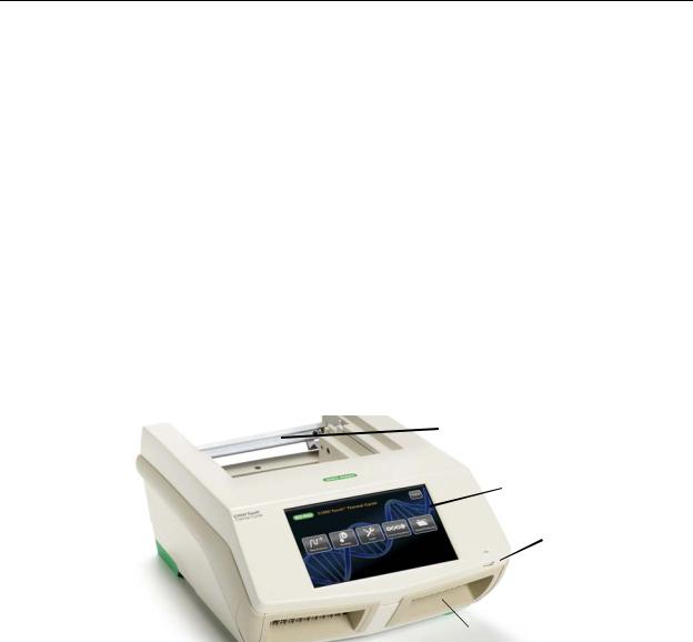
System Overview
The C1000 Touch thermal cycler base (Figure 1) includes:
•Reaction module bay — holds the inserted reaction module
•Reaction module locking bar —locks reaction module in place
•Touchscreen display— provides access to all the functions needed to create and run PCR protocols
•USB A port — connects to a USB flash drive, mouse, or keyboard
•Air intake vents — allow the thermal cycler to heat and cool quickly
Reaction module locking bar
 Reaction module bay
Touchscreen display
USB A port
 Air intake vents
Figure 1. Front view of the C1000 Touch thermal cycler.
1
C1000 TouchTM Thermal Cycler Manual
The back panel of the C1000 Touch thermal cycler includes data ports (Figure 2).
•USB B port — connects the C1000 Touch thermal cycler to a computer
•USB A ports — connects up to three S1000 thermal cyclers to the C1000 Touch thermal cycler. These ports can also connect to any USB flash drive, mouse, or keyboard
•Test port — for service testing only
•Ethernet port — for connecting the C1000 Touch thermal cycler to your network
USB B port |
|
|
||
Ethernet |
USB A ports |
|||
port |
||||
|
|
|||
|
|
|
|
|
Power switch
Power input
Fuses
|
|
|
|
Cooling vents |
Test port |
||
Figure 2. Back panel of the C1000 Touch thermal cycler.
Reaction Modules
The C1000 Touch thermal cycler is compatible with any 1000-series reaction module. The reaction modules come in four module sizes: the 96-well fast module, 96–deep well module, dual 48/48-well fast module, or 384-well module. Each reaction module includes a fully adjustable heated lid that is capable of running reliably with a broad range of reaction vessels.
Recommended Sample Volumes
When using the C1000 Touch thermal cycler, the maximum sample volume is determined by the type of reaction module used. Table 6 lists the volumes to be used with different reaction modules.
Table 6. Size and volume limit for 1000-series reaction modules.
Number of Wells |
Number of |
Recommended Sample |
|
Blocks |
Volume (Upper Limit) |
||
|
|||
|
|
|
|
96 fast |
1 |
10–50 μl (50 μl limit) |
|
|
|
|
|
96 deep |
1 |
10–125 μl (125 μl limit) |
|
|
|
|
|
Dual 48/48 fast |
2 |
10–50 μl (50 μl limit) |
|
|
|
|
|
384 |
1 |
3–30 μl (30 μl limit) |
|
|
|
|
Each reaction module contains cooling fins for fast heating and cooling and a fully adjustable, heated lid.
•Heated inner lid — maintains the lid temperature to prevent condensation and evaporation
•Sample/reaction block —holds reaction vessels, including tubes and microplates
The top of a reaction module lid includes a lid lever, lid force knob, and status LED.
2

C1000 TouchTM Thermal Cycler Manual
•Lid lever — opens and closes the lid
•Lid force knob — sets lid force and seals the reaction
•Status LED — turns on to indicate that the block is in use
Figure 3 shows the components of a 96-well fast reaction module.
Lid force knob
Lid
Lid lever
Status LED
Cooling fins
Figure 3. Components of a reaction module.
Setting Up the C1000 Touch Thermal Cycler
The C1000 Touch thermal cycler package includes:
•C1000 Touch thermal cycler base
•Power cord
•1 USB flash drive
•Instruction manual
•Quick guide for system installation
Reaction modules for use with the C1000 Touch thermal cycler are shipped in separate packaging. Remove all packaging materials and store them for future use. If any item is missing or damaged, contact your local Bio-Rad office.
Place the C1000 Touch thermal cycler base on a flat, dry surface with sufficient cool airflow to run properly.
The instrument can run in two modes: stand-alone or software-controlled by CFX ManagerTM software version 2.1 or higher. When running the system in software-controlled mode, make sure there is sufficient space for a computer during setup.
3

C1000 TouchTM Thermal Cycler Manual
To insert a 1000-series reaction module into the reaction module bay of the thermal cycler base, follow these instructions:
1.With the locking bar in the down position and the lid lever of the reaction module pointing to the front, lift the reaction module into the reaction module bay (Figure 4). Leave 1–2 cm of space in front of the module.
Lid lever (front)
Leave space here
Locking bar (down position when unlocked)
Figure 4. Inserting the reaction module into the bay.
2.Pull the locking bar up to lock the reaction module in place (Figure 5). There should be no space at the front of the module when it is locked into the C1000 Touch thermal cycler base.
No space |
|
Locking bar |
|
(up position |
|
(in locked position) |
|
|
|
when locked) |
|
|
|
Figure 5. Locking the reaction module in place.
3.Plug the supplied power cord into the appropriate electrical outlet.
4.Turn on the thermal cycler using the power switch on the back panel of the thermal cycler base.
NOTE: Before operating the thermal cycler, be sure to read the safety specifications (“Safety and Regulatory Compliance” on page iii) and operating requirements.
5.When the C1000 Touch thermal cycler starts, it runs a self-test to verify proper functions, and then displays the home screen. Use the home screen to begin operating the thermal cycler.
To remove the reaction module from the thermal cycler base, follow these instructions:
1.Turn off the thermal cycler.
2.Unlock and release the reaction module by pushing the locking bar down.
3.Carefully lift the reaction module out of the bay.
WARNING! Cooling fins may be hot immediately after running a protocol or incubation. Before lifting the reaction module, make sure the fins are cool.
4.After removing the reaction module from the C1000 Touch thermal cycler, store it on a clean, flat surface where it cannot get bumped, scraped, or dropped.
4

C1000 TouchTM Thermal Cycler Manual
Operating the Reaction Module Lid
The inner lid of the reaction module applies heat and force to the reaction vessel lids (caps or tape) to produce consistent and successful reactions. Heating the inner lid prevents condensation, while applying force seals the reaction to prevent evaporation.
WARNING! After a run, the heated inner lid can remain hot. Use caution when opening and closing the lid.
To open the lid, use the following steps:
1. Turn the lid force knob counterclockwise to release the inner lid (Figure 6).
Lid force knob
(turn counterclockwise to release the lid)
Figure 6. Turn the lid force knob counterclockwise to release the inner lid.
2.To open the lid, lift the lid lever up.
3.Lift the lid lever completely until the reaction module stays open without assistance.
To close the lid, follow these steps:
1.Push the lid lever down, making sure that the front of the lid is secured beneath the housing.
2.Adjust the lid force by turning the lid force knob (Figure 7).
•Turn the knob clockwise to increase the lid force
•Turn the knob counterclockwise to decrease the lid force
3.Increase the lid force until the heated lid touches the reaction vessel. Continue to increase the lid force further based on the following recommendations.
•If using tubes, increase the lid force by a quarter turn after the lid touches the tubes
•If using plates, increase the lid force by a half turn after the lid touches the plate
NOTE: The position marks on the lid indicate quarter turns
WARNING! If the lid is tightened past the recommended force, tightening the lid further will result in the knob slipping and causing a clicking sound. This is designed as a warning that the lid force is past the recommended setting and may result in damage to the reaction vessels. If this happens, decrease the lid force by
5

C1000 TouchTM Thermal Cycler Manual
turning the lid force knob counterclockwise one full turn. Reapply the correct lid force by following the instructions in step 3.
 Lid force knob (turn clockwise to secure the lid)
Figure 7. Adjust the lid force by turning the lid force knob.
Loading Sample Vessels into the Reaction Block
To ensure uniform heating and cooling of samples, vessels must be in complete contact with the reaction block. Adequate contact is achieved by:
•Confirming that the block is clean before loading samples
•Firmly pressing the individual tubes or the microplate into the block wells
TIP: When using one or a few tubes, use the tube frame (catalog #184-9000 or 184-9001) or load at least one empty tube in each corner of the block to ensure that the lid exerts even pressure on individual tubes.
The Home Screen
The home screen provides access to all thermal cycler operations and displays the status of the reaction module and the name of the thermal cycler. In the example shown in Figure 8, the home screen displays the date and time, name of logged-in user (Pete), name of the instrument (CC006622), current status (Idle), and home screen buttons.
Figure 8. The home screen of the C1000 Touch thermal cycler.
6

C1000 TouchTM Thermal Cycler Manual
To initiate the functions on the home screen, touch the associated button. Below are choices of functions:
•New Protocol — Create a new protocol (page 11)
•Protocol AutoWriter — Create a new protocol by entering amplicon length, annealing temperature and desired speed (page 27)
•Saved Files — View the saved files and folders in the file library (page 33)
•Incubate — Opens the incubate setup screen (page 25)
•Tools — Opens the tools screen (page 40)
•Log in — Log in to the C1000 Touch thermal cycler. Once you log in, the button name changes to Log Off (page 39)
•Status — Open the status screen to view the current status of the reaction module (page 23)
Renaming the C1000 Touch Thermal Cycler
Each C1000 Touch thermal cycler is initially named using the serial number of the thermal cycler base. Users can rename a thermal cycler for easy identification.
To rename a C1000 touch thermal cycler, follow these steps:
1.From the home screen, touch the Tools button to open the tools menu. Touch About, then touch the Name button (Figure 9).
2.Enter a new name using the pop-up alphanumeric keypad.
3.Touch the OK button to accept the new cycler name.
Figure 9. Touch the Name button to rename the instrument.
7
C1000 TouchTM Thermal Cycler Manual
Setting Up Email Notification
A run complete confirmation and run report can be emailed directly to any computer with Internet access. To configure the outgoing email from the C1000 Touch thermal cycler, use the following instructions:
1.Touch the Log In button on the home screen to log in to the thermal cycler as the Administrator.
NOTE: The logged in user name appears to the left of the log out button when you return to the home screen.
2.Touch the Tools button on the home screen to launch the tools menu.
3.Touch Email Settings in the admin menu.
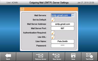
Setting Up the Gmail server
NOTE: A Gmail account must be set up with user name and password prior to setting up the instrument Gmail server.
1.Select the Gmail server from the Mail Server dropdown list.
2.Enter the Gmail account user name and password.
3.Touch the Set as Default checkbox (Figure 10).
Figure 10. Gmail server is selected, user name and password have been entered, and server has been selected as the default server.
4.Touch the Save button to save the current server settings.
5.Touch the Test Email button.
6.Touch the Test Email Address button and enter an email address using the pop-up alphanumeric keypad.
7.Touch the Attachment Size in MB button and enter a test attachment size.
NOTE: The allowable limit on attachment size is dictated by your institute’s server. We recommend testing an attachment size between 0.5 and 5 MB. Entering 0 will send a test email with no attachment.
8

C1000 TouchTM Thermal Cycler Manual
8. Touch the Send Email button.
A test email will be sent to the test email address.
9. Touch the Cancel button to return to the server settings screen. 10.Touch the Back button to return to the tools menu.
Setting up a custom server
1. Touch the New Server button (Figure 11).
Figure 11. New Server button.
2.Touch the Mail Server Address button and enter an address using the pop-up alphanumeric keypad.
3.Touch the Mail Server Port button and enter a value using the pop-up numeric keypad.
4.Touch the Set As Default checkbox.
5.Enter additional information (Authentication Required, Use SSL, User Name, and Password) only if required by your server.
TIP: Contact your network administrator for server requirements.
6.Touch the Save button. The new server will appear in the Mail Servers dropdown list.
7.Repeat steps 5-10 in “Setting Up the Gmail server” (page 8).
Removing a server
1.Select the server to be removed in the Mail Servers dropdown list.
2.Touch the Remove Server button.
3.Touch the Yes button to confirm removal of selected server.
9
C1000 TouchTM Thermal Cycler Manual
10
 Loading...