


 ®
®
P4S533-E
User Guide
Motherboard

P4S533-E
E1034
June 2002
Copyright © 2002 ASUSTeK COMPUTER INC. All Rights Reserved.
No part of this manual, including the products and software described in it, may be reproduced, transmitted, transcribed, stored in a retrieval system, or translated into any language in any form or by any means, except documentation kept by the purchaser for backup purposes, without the express written permission of ASUSTeK COMPUTER INC. (“ASUS”).
Product warranty or service will not be extended if: (1) the product is repaired, modified or altered, unless such repair, modification of alteration is authorized in writing by ASUS; or (2) the serial number of the product is defaced or missing.
Products and corporate names appearing in this manual may or may not be registered trademarks or copyrights of their respective companies, and are used only for identification or explanation and to the owners’ benefit, without intent to infringe.
The product name and revision number are both printed on the product itself. Manual revisions are released for each product design represented by the digit before and after the period of the manual revision number. Manual updates are represented by the third digit in the manual revision number.
For previous or updated manuals, BIOS, drivers, or product release information, contact ASUS at: http://www.asus.com or through any of the means indicated on the following page.
ASUS PROVIDES THIS MANUAL “AS IS” WITHOUT WARRANTY OF ANY KIND, EITHER EXPRESS OR IMPLIED, INCLUDING BUT NOT LIMITED TO THE IMPLIED WARRANTIES OR CONDITIONS OF MERCHANTABILITY OR FITNESS FOR A PARTICULAR PURPOSE. IN NO EVENT SHALL ASUS, ITS DIRECTORS, OFFICERS, EMPLOYEES OR AGENTS BE LIABLE FOR ANY INDIRECT, SPECIAL, INCIDENTAL, OR CONSEQUENTIAL DAMAGES (INCLUDING DAMAGES FOR LOSS OF PROFITS, LOSS OF BUSINESS, LOSS OF USE OR DATA, INTERRUPTION OF BUSINESS AND THE LIKE), EVEN IF ASUS HAS BEEN ADVISED OF THE POSSIBILITY OF SUCH DAMAGES ARISING FROM ANY DEFECT OR ERROR IN THIS MANUAL OR PRODUCT.
SPECIFICATIONS AND INFORMATION CONTAINED IN THIS MANUAL ARE FURNISHED FOR INFORMATIONAL USE ONLY, AND ARE SUBJECT TO CHANGE AT ANY TIME WITHOUT NOTICE, AND SHOULD NOT BE CONSTRUED AS A COMMITMENT BY ASUS. ASUS ASSUMES NO RESPONSIBILITY OR LIABILITY FOR ANY ERRORS OR INACCURACIES THAT MAY APPEAR IN THIS MANUAL, INCLUDING THE PRODUCTS AND SOFTWARE DESCRIBED IN IT.
ii

About this guide
This user manual contains complete information for installing the ASUS P4S533-E motherboard.
How this guide is organized
•Chapter 1: Product introduction. A summary of product features and special attributes of new technologies.
•Chapter 2: Hardware information. A list of hardware setup procedures and descriptions of all jumpers and connectors on the motherboard.
•Chapter 3: Powering up. Describes the power up sequence with information on BIOS beep codes.
•Chapter 4: BIOS setup. How to change system settings using onboard BIOS firmware. Detailed descriptions of the BIOS parameters are supplied.
•Chapter 5: Software support. A summary of contents on the motherboard support CD ROM.
•Appendix and Glossary. Optional components and technical definitions.
•Index
Conventions used in this guide
To make sure that you perform set-up tasks properly, take note of the following symbols used throughout this manual.
WARNING! Information to prevent injury to yourself.
CAUTION! Information to prevent damage to the components.
IMPORTANT! Information that you MUST follow to complete a task.
NOTE! Tips and helpful information.
iii

Contents
About this guide .............................................................................. |
iii |
How this guide is organized .................................................... |
iii |
Conventions used in this guide ............................................... |
iii |
Safety information ........................................................................... |
vi |
FCC/CDC statements .................................................................... |
vii |
ASUS contact information ............................................................. |
viii |
Chapter |
1: Product introduction ............................................. |
1 |
Welcome! ........................................................................................ |
1 |
|
1.1 |
Package contents .................................................................. |
1 |
1.2 |
Core Specifications ................................................................ |
2 |
1.3 |
Special Features .................................................................... |
3 |
1.4 |
Motherboard Components ...................................................... |
4 |
|
1.4.1 Component Locations ................................................ |
5 |
Chapter 2: Hardware information ............................................ |
7 |
||
2.1 |
Motherboard installation ......................................................... |
7 |
|
|
2.1.1 |
Placement direction ................................................... |
7 |
|
2.1.2 |
Screw holes ............................................................... |
7 |
2.2 |
Motherboard layout ................................................................ |
8 |
|
|
2.2.1 |
Layout contents ......................................................... |
9 |
2.3 |
Before you proceed ............................................................... |
10 |
|
2.4 |
Central Processing Unit (CPU) .............................................. |
11 |
|
|
2.4.1 |
Overview .................................................................. |
11 |
|
2.4.2 |
Installing the CPU .................................................... |
12 |
|
2.4.3 Installing the heatsink and fan .................................. |
14 |
|
|
2.4.4 Connecting the CPU fan cable ................................. |
16 |
|
2.5 |
System memory .................................................................... |
17 |
|
|
2.5.1 |
Overview .................................................................. |
17 |
|
2.5.2 |
Memory configurations ............................................ |
18 |
|
2.5.3 |
Installing a DIMM ..................................................... |
19 |
|
2.5.4 |
Removing a DIMM ................................................... |
20 |
2.6 |
Expansion slots ..................................................................... |
21 |
|
|
2.6.1 Installing an expansion card ..................................... |
21 |
|
|
2.6.2 Configuring an expansion card ................................ |
22 |
|
|
2.6.3 |
PCI slots ................................................................... |
23 |
|
2.6.4 |
AGP slot ................................................................... |
23 |
2.7 |
Jumpers ................................................................................ |
24 |
|
2.8 |
Connectors ........................................................................... |
31 |
|
iv

Contents
Chapter 3: Powering up ......................................................... |
45 |
|
3.1 |
Starting up for the first time................................................... |
45 |
3.2 |
Vocal POST Messages ......................................................... |
46 |
3.3 |
Powering off the computer.................................................... |
48 |
Chapter 4: BIOS setup ........................................................... |
49 |
||
4.1 |
Managing and updating your BIOS....................................... |
49 |
|
|
4.1.1 Using the computer system for the first time ............ |
49 |
|
|
4.1.2 |
Updating BIOS procedures ...................................... |
51 |
4.2 |
BIOS Setup program ............................................................. |
53 |
|
|
4.2.1 |
BIOS menu bar ......................................................... |
54 |
|
4.2.2 |
Legend bar ............................................................... |
54 |
4.3 |
Main menu ............................................................................ |
56 |
|
|
4.3.1 Primary & Secondary Master/Slave ......................... |
57 |
|
|
4.3.2 |
Keyboard Features .................................................. |
61 |
4.4 |
Advanced Menu .................................................................... |
63 |
|
|
4.4.1 |
Chip Configuration ................................................... |
65 |
|
4.4.2 |
I/O Device Configuration .......................................... |
68 |
|
4.4.3 |
PCI Configuration .................................................... |
70 |
4.5 |
Power Menu .......................................................................... |
73 |
|
|
4.5.1 |
Power Up Control .................................................... |
75 |
|
4.5.2 |
Hardware Monitor .................................................... |
77 |
4.6 |
Boot Menu ............................................................................ |
78 |
|
4.7 |
Exit Menu .............................................................................. |
80 |
|
Chapter 5: Software support ................................................. |
83 |
|
5.1 |
Install an operating system ................................................... |
83 |
5.2 |
Support CD information ......................................................... |
83 |
5.3 |
P4S533-E Motherboard Support CD .................................... |
84 |
5.4 |
ASUS PC Probe.................................................................... |
86 |
5.5 |
ASUS Live Update ................................................................ |
91 |
5.6 |
3Deep Color Tuner ................................................................ |
92 |
5.7 |
ITE GSM Editor ..................................................................... |
94 |
5.8 |
Winbond Voice Editor ............................................................ |
98 |
Glossary ................................................................................ |
103 |
|
Index |
...................................................................................... |
107 |
v

Safety information
Electrical safety
•To prevent electrical shock hazard, disconnect the power cable from the electrical outlet before relocating the system.
•When adding or removing devices to or from the system, ensure that the power cables for the devices are unplugged before the signal cables are connected. Disconnect all power cables from the existing system before you add a device.
•Before connecting or removing signal cables from the motherboard, ensure that all power cables are unplugged.
•Seek professional assistance before using an adpater or extension cord. These devices could interrupt the grounding circuit.
•Make sure that your power supply is set to the voltage available in your area.
•If the power supply is broken, contact a qualified service technician or your retailer.
Operational safety
•Before installing the motherboard and adding new devices, carefully read all the manuals that came with the package.
•Before use ensure all cables are correctly connected and the power cables are not damaged. If you detect any damage, contact the dealer immediately.
•To avoid short circuits, keep paper clips, screws, and staples away from connectors, slots, sockets and circuitry.
•Avoid dust, humidity, and temperature extremes. Do not place the product in any area where it may become wet.
•Mount the motherboard inside a standard PC enclosure.
•If you encounter technical problems with the product, contact a qualified service technician or the dealer.
vi

FCC/CDC statements
Federal Communications Commission Statement
This device complies with FCC Rules Part 15. Operation is subject to the following two conditions:
•This device may not cause harmful interference, and
•This device must accept any interference received including interference that may cause undesired operation.
This equipment has been tested and found to comply with the limits for a Class B digital device, pursuant to Part 15 of the FCC Rules. These limits are designed to provide reasonable protection against harmful interference in a residential installation. This equipment generates, uses and can radiate radio frequency energy and, if not installed and used in accordance with manufacturer’s instructions, may cause harmful interference to radio communications. However, there is no guarantee that interference will not occur in a particular installation. If this equipment does cause harmful interference to radio or television reception, which can be determined by turning the equipment off and on, the user is encouraged to try to correct the interference by one or more of the following measures:
•Reorient or relocate the receiving antenna.
•Increase the separation between the equipment and receiver.
•Connect the equipment to an outlet on a circuit different from that to which the receiver is connected.
•Consult the dealer or an experienced radio/TV technician for help.
The use of shielded cables for connection of the monitor to the graphics card is required to assure compliance with FCC regulations. Changes or modifications to this unit not expressly approved by the party responsible for compliance could void the user’s authority to operate this equipment.
Canadian Department of Communications Statement
This digital apparatus does not exceed the Class B limits for radio noise emissions from digital apparatus set out in the Radio Interference Regulations of the Canadian Department of Communications.
This class B digital apparatus complies with Canadian ICES-003.
vii

ASUS contact information
ASUSTeK COMPUTER INC. (Asia-Pacific)
Address: |
150 Li-Te Road, Peitou, Taipei, Taiwan 112 |
General Tel: |
+886-2-2894-3447 |
General Fax: |
+886-2-2894-3449 |
General Email: |
info@asus.com.tw |
Technical Support:
MB/Others (Tel): |
+886-2-2890-7121 (English) |
|
Notebook (Tel): |
+886-2-2890-7122 |
(English) |
Desktop/Server (Tel): |
+886-2-2890-7123 |
(English) |
Support Fax: |
+886-2-2890-7698 |
|
Support Email: |
tsd@asus.com.tw |
|
Web Site: |
www.asus.com.tw |
|
Newsgroup: |
cscnews.asus.com.tw |
|
ASUS COMPUTER INTERNATIONAL (America)
Address: |
6737 Mowry Avenue, Mowry Business Center, |
|
Building 2, Newark, CA 94560, USA |
General Fax: |
+1-510-608-4555 |
General Email: |
tmd1@asus.com |
Technical Support:
Support Fax: |
+1-510-608-4555 |
General Support: |
+1-502-995-0883 |
Notebook Support: |
+1-877-918-ASUS (2787) |
Web Site: |
www.asus.com |
Support Email: |
tsd@asus.com |
ASUS COMPUTER GmbH (Europe)
Address: |
Harkortstr. 25, 40880 Ratingen, BRD, Germany |
General Fax: |
+49-2102-442066 |
General Email: |
sales@asuscom.de (for marketing requests only) |
Technical Support:
Support Hotline: |
MB/Others: +49-2102-9599-0 |
Notebook (Tel): |
+49-2102-9599-10 |
Support Fax: |
+49-2102-9599-11 |
Support (Email): |
www.asuscom.de/de/support (for online support) |
Web Site: |
www.asuscom.de |
viii
Chapter 1
Product introduction

ASUS P4S533-E motherboard
Welcome!
Thank you for buying the ASUS® P4S533-E motherboard!
The ASUS P4S533-E motherboard delivers a host of new features to ensure long-lasting, superlative performance. The ASUS® P4S533-E motherboard is the prime choice for home PCs and workstations.
The P4S533-E incorporates the Intel® Pentium® 4 Processor coupled with the SiS 645DX chipset to set a new benchmark for an effective desktop platform solution.
~CPU Thermal Protection
~Up to 3GB of system memory of DDR200/266/333 DRAM
~High-resolution graphics via an AGP 4X slot
~Digital Audio Interface for 3D sound
~Realtek™ LAN Controller onboard
~ASUS Post Reporter™ onboard
~Two USB ports plus two headers for four more
Before installing the motherboard, check the items in your package:
1.1Package contents
Check your P4S533-E package for the following items.
ASUS P4S533-E motherboard (ATX form factor: 12-in x 8.6-in)
ASUS P4S533-E support CD
ASUS 4-port USB 2.0 cable
80-conductor ribbon cable for UltraDMA/33/66/100/133 IDE drives
40-conductor IDE cable
Ribbon cable for a 3.5-inch floppy drive
Bag of extra jumper caps
1394 connector cable
1394 PCI card
User Guide
If any of the above items is damaged or missing, contact your retailer.
ASUS P4S533-E motherboard user guide |
1 |

1.2Core Specifications
The P4S533-E motherboard is designed and assembled according to the highest standards. This ASUS motherboard represents the latest advances to supply users the finest componentry available today...
Latest 533MHz P4 Processor Technology: Intel Pentium 4 Socket 478 Northwood Processor. The Pentium 4 processor utilizes the advanced 0.18 micron processor core in FC-PGA2 package for a 2.0GHz frequency, while the Northwood processor uses the 0.13 micron processor core with 512KB L2 cache for up to a speedy 2.2+ GHz frequency and a 533 MHz FSB. The P4 optimizes audio, video, and Internet applications.
North Bridge Chipset: the SiS® 645DX supports AGP 4X/2X mode, 133/100MHz Front Side Bus, and the fastest 333 MHz memory bus.
South Bridge Chipset: the SiS® 962 / 962/L integrated peripheral controller supports UltraDMA133/100/66/33 for burst mode data transfer rates up to 133MB/sec, and USB controller with two root hubs for six USB ports.
PC 2700 / 2100 / 1600 DDR Support: Equipped with three Double Data Rate Dual Inline Memory Module (DDR DIMM) sockets to support up to 3GB of DDR DRAM, the newest memory standard with the highest bandwidth and lowest latency currently available. This new memory technology increases performance by executing two actions per clock cycle, resulting in data transfer rates of up to 2.7 GB/s for 166MHz DDR SDRAM and 2.1GB/s for 133MHz DDR SDRAM. (Only 4 banks of DDR333 memory, or 2GB, are supported on the P4S533-E.)
UltraDMA133 Support: Comes with an onboard PCI Bus Master IDE controller with two connectors that support four IDE devices on two channels. Supports UltraDMA133/100/66/33, PIO Modes 3 & 4, Bus Master IDE DMA Mode 2, and Enhanced IDE devices, such as DVDROM, CD-ROM, CD-R/RW, LS-120, and Tape Backup drives.
Multi-I/O Chipset: The ITE 8707F chip offers complete support for a variety of I/O functions. Provides two high-speed UART compatible serial ports and one parallel port with EPP and ECP capabilities. UART2 can switch from COM2 to the Infrared Module for wireless connections. The Super I/ O controller supports a floppy disk drive, PS/2 keyboard, and PS/2 mouse.
Smart BIOS: 2Mb firmware enables Vcore and CPU/DDR SDRAM frequency adjustments, boot block write protection, and HD/SCSI/MO/ZIP/CD/Floppy boot selection.
Expansion: One AGP 4X, four USB ports, two COM ports, six PCI slots, SPDIF digital audio, iPanel, front audio panel, SMB, three IEEE-1394 headers, smart card, CIR infrared.
Connections: Parallel, PS/2 mouse, PS/2 keyboard, 2 USB, RJ45 (optional), Microphone, Line-In / Line-Out jacks, Standard ATX, AUX and 12V power.
2 |
Chapter 1: Product introduction |

1.3Special Features
Easy Overclocking
•Quickly adjust CPU frequency multiples with BIOS in JumperFree™ Mode
•Adjustable FSB/MEM/PCI frequency ratio
•Stepless Frequency Selection (SFS) for fine-tuning system bus frequency from at 1MHz increments
•Optimal system performance available with BIOS built-in Turbo Mode
ASUS EZ Plug™ |
(See page 38.) |
This patented ASUS technology uses the existing power supply instead of having to buy a new ATX 12V power supply: ASUS EZ Plug™ is a 4-pin +12V connector that provides additional power required by P4 CPUs.
ASUS EZ Flash BIOS |
(See page 51.) |
With the ASUS EZ Flash, you can easily update the system BIOS even before loading the operating system. No need to use a DOS-based utility or boot from a floppy disk.
ASUS POST Reporter™  (See page 27, 44, 79 and 88.)
P4S533-E offers the ASUS POST Reporter™ to provide friendly voice messages and alerts during the Power-On Self-Test (POST). Through the system’s internal speaker, or an added external speaker, messages inform you of system boot status and causes of boot errors. Bundled Winbond™ Voice Editor software helpsa you customize voice messages, and offers multi-language support.
ASUS MYLogo2™  (See page 98.)
This new feature present in the P4S533-E motherboard allows you to personalize and add style to your system with customizable boot logos.
ASUS Q-Fan feature |
(See page 77.) |
The ASUS Q-Fan technology smartly adjusts the fan speeds according to the system loading to ensure quiet, cool, and efficient operation.
ASUS Multi-language BIOS |
(See page 56.) |
The multi-language BIOS offers the language of your choice from several options. Localized BIOS menus are easy to configure. Visit the ASUS website for the supported languages.
ASUS P4S533-E motherboard user guide |
3 |

1.4Motherboard Components
Before installing the P4S533-E motherboard, take time to familiarize yourself with its configuration: understanding the motherboard makes upgrading easy. Sufficient knowledge of specifications prevents accidental damage.
|
|
|
Location |
|
Processor Support |
Socket 478 for Intel® P4™ Processors ............................. |
|
2 |
|
|
Feature setting DSW ....................................................... |
|
9 |
|
Chipsets |
SiS® |
645DX North Bridge ................................................ |
|
7 |
|
SiS® |
962/L South Bridge ............................................... |
|
17 |
|
Speech Module ............................................................. |
|
13 |
|
|
4Mbit Programmable Flash EEPROM .......................... |
|
22 |
|
|
Multi-I/O Controller ........................................................ |
|
18 |
|
|
Audio Controller ............................................................ |
|
26 |
|
Main Memory |
3 DDR SDRAM DIMM Sockets (3GB) ............................ |
|
4 |
|
Expansion Slots |
6 PCI Slots .................................................................... |
|
24 |
|
|
Accelerated Graphics Port (AGP) 4X Slot ..................... |
|
30 |
|
System I/O |
Floppy Disk Drive Connector .......................................... |
|
6 |
|
|
2 IDE Connectors (UltraDMA133 Support) ..................... |
|
8 |
|
|
SMB Bus Connector ...................................................... |
|
10 |
|
|
Smart Card Connector .................................................. |
|
11 |
|
|
Infrared Connector ........................................................ |
|
12 |
|
|
iPanel Connector ........................................................... |
|
14 |
|
|
System Panel Connector .............................................. |
|
15 |
|
|
3 IEEE-1394 Headers ................................................... |
|
19 |
|
|
USB Headers (USB2, USB3) ........................................ |
|
20 |
|
|
Modem Connector ......................................................... |
|
23 |
|
|
Parallel Port ................................................................... |
|
33 |
|
|
Game-MIDI Port ............................................................ |
|
34 |
|
|
2 Serial Ports (COM1/2) ................................................ |
|
38 |
|
|
USB Connectors (Port 0/1) .......................................... |
|
39 |
|
|
PS/2 Mouse Connector .................................... |
(green) 31 |
||
|
PS/2 Keyboard Connector ............................. |
(purple) 40 |
||
Hardware Monitoring System Voltage Monitor (integrated in ASUS ASIC) ..... |
16 |
|||
Special Feature |
Onboard LED ................................................................ |
|
21 |
|
Network Feature |
RJ45 Connector (Optional) ........................................... |
|
32 |
|
|
Realtek 100/10 Mbps LAN PHY (Optional) ................... |
|
28 |
|
Audio Features |
(on audio models only) |
|
|
|
|
Audio Controller Chipset ............................................... |
|
26 |
|
|
SPDIF-in/out Connector ................................................ |
|
25 |
|
|
Front Panel Audio Header ............................................. |
|
27 |
|
|
Audio Connectors .......................................................... |
|
29 |
|
|
Line Out Connector ............................................ |
(lime) 37 |
||
|
Line In Connector ...................................... |
(light blue) 36 |
||
|
Microphone Connector ....................................... |
(pink) 35 |
||
Power |
ATX 12V Power Supply Connector ................................. |
|
1 |
|
|
ATX Power Supply Connector ......................................... |
|
3 |
|
|
AUX12V1 EZ-Plug Power Supply Connector .................. |
5 |
||
Form Factor |
ATX |
|
|
|
4 |
Chapter 1: Product introduction |
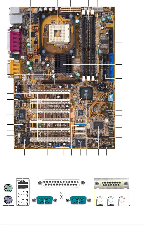
1.4.1 Component Locations
1 |
2 |
3 |
4 |
5 |
30
29 

28
27
26
25
24
23
6
7
8
9
10
11

 12 13
12 13
14
|
|
|
|
|
|
22 |
21 |
|
20 |
19 |
18 17 |
16 |
15 |
|
|
|
|
|
|
|
|||||||||||||||||||||||
|
31 |
|
|
32 |
|
|
|
|
|
|
|
|
|
33 |
|
|
|
|
|
|
|
|
|
34 |
|
|
|
|
|||||||||||||||
|
|
|
|
|
|
|
|
|
|
|
|
|
|
|
|
|
|
|
|
|
|
|
|
|
|
|
|
|
|
|
|
|
|
|
|
|
|
|
|
|
|
|
|
|
|
|
|
|
|
|
|
|
|
|
|
|
|
|
|
|
|
|
|
|
|
|
|
|
|
|
|
|
|
|
|
|
|
|
|
|
|
|
|
|
|
|
|
|
|
|
|
|
|
|
|
|
|
|
|
|
|
|
|
|
|
|
|
|
|
|
|
|
|
|
|
|
|
|
|
|
|
|
|
|
|
|
|
|
|
|
|
|
|
|
|
|
|
|
|
|
|
|
|
|
|
|
|
|
|
|
|
|
|
|
|
|
|
|
|
|
|
|
|
|
|
|
|
|
|
|
|
|
|
|
|
|
|
|
|
|
|
|
|
|
|
|
|
|
|
|
|
|
|
|
|
|
|
|
|
|
|
|
|
|
|
|
|
|
|
|
|
|
|
|
|
|
|
|
|
|
|
|
|
|
|
|
|
|
|
|
|
|
|
|
|
|
|
|
|
|
|
|
|
|
|
|
|
|
|
|
|
|
|
|
|
|
|
|
|
|
|
|
|
|
|
|
|
|
|
|
|
|
|
|
|
|
|
|
|
|
|
|
|
|
|
|
|
|
|
|
|
|
|
|
|
|
|
|
|
|
|
|
|
|
|
|
|
|
|
|
|
|
|
|
|
|
|
|
|
|
|
|
|
|
|
|
|
|
|
|
|
|
|
|
|
|
|
|
|
|
|
|
|
|
|
|
|
|
|
|
|
|
|
|
|
|
|
|
|
|
|
|
|
|
|
|
|
|
|
|
|
|
|
|
|
|
|
|
|
|
|
|
|
|
|
|
|
|
|
|
|
|
|
|
|
|
|
|
|
|
|
|
|
|
|
|
|
|
|
|
|
|
|
|
|
|
|
|
|
|
|
|
|
|
|
|
|
|
|
|
|
|
|
|
|
|
|
|
|
|
|
|
|
|
|
|
|
|
|
|
|
|
|
|
|
|
|
|
|
|
|
|
|
|
|
|
|
|
|
|
|
|
|
|
|
|
|
|
|
|
|
|
|
|
|
|
|
|
|
|
|
|
|
|
|
|
|
|
|
|
|
|
|
|
|
|
|
|
|
|
|
|
|
|
|
|
|
|
|
|
|
|
|
|
|
|
|
|
|
|
|
|
|
|
|
|
|
|
|
|
|
|
|
|
|
|
|
|
|
|
|
|
|
|
|
|
|
|
|
|
|
|
|
|
|
|
|
|
|
|
|
|
|
|
|
|
|
|
|
|
|
|
|
|
|
|
|
|
|
|
|
|
|
|
|
|
|
|
|
|
|
|
|
|
|
|
|
|
|
|
|
|
|
|
|
|
|
|
|
|
|
|
|
|
|
|
|
|
|
|
|
|
|
|
|
|
|
|
|
|
|
|
|
|
|
|
|
|
|
|
|
|
|
|
|
|
|
|
|
|
|
|
|
|
|
|
|
|
|
|
|
|
|
|
|
|
|
|
|
|
|
|
|
|
|
|
|
|
|
|
|
|
|
|
|
|
|
|
|
|
|
|
|
|
|
|
|
|
|
|
|
|
|
|
|
|
|
|
|
|
|
|
|
|
|
|
|
|
|
|
|
|
|
|
|
|
|
|
|
|
|
|
|
|
|
|
|
|
|
|
|
|
|
|
|
|
|
|
|
|
|
|
|
|
|
|
|
|
|
|
|
|
|
|
|
|
|
|
|
|
|
|
|
|
|
|
|
|
|
|
|
|
|
|
|
|
|
|
|
|
|
|
|
|
|
|
|
|
|
|
|
|
|
|
|
|
|
|
|
|
|
|
|
|
|
|
|
|
|
|
|
|
|
|
|
|
|
|
|
|
|
|
|
|
|
|
|
|
|
|
|
|
|
|
|
|
|
|
|
|
|
|
|
|
|
|
|
|
|
|
|
|
|
|
|
|
|
|
|
40 |
39 |
38 |
37 |
36 |
35 |
ASUS P4S533-E motherboard user guide |
5 |
1.5Value-added solutions
PCI Audio: On audio models, a digital audiochip., CMI-8738, and a special connector supports the Sony/Philips Digital Interface (S/PDIF) Output/ Input module for coaxial and fiber interfaces. Experience surround sound and enhanced 3D audio.
Smart Card Reader Support: A special connector for the Smart Card Reader comes onboard to support the cutting-edge technology for increased security in authenticating online transactions, editing IC-based information.
USB2.0: The latest connection standard for next generation components and peripherals. Compatible with 1.1 USB, the new 2.0 USB protocol delivers transfer speeds up to 40 times faster at 480Mb/s. NOTE: USB 2.0 is not supported under Win98/WinME.
Temperature, Fan and Voltage Monitoring: CPU temperature is monitored by the ASUS ASIC through the CPU’s internal thermal diode to prevent overheating and damage. All system fans are monitored for RPM and failure. System voltage levels are monitored to ensure stable voltage to critical motherboard components.
Auto Fan Off: The system fans powers off automatically even in sleep mode.
ACPI Ready: Advanced Configuration Power Interface (ACPI) provides more Energy Saving Features for operating systems that support OS Direct Power Management (OSPM).
Onboard LAN (Optional): The motherboard incorporates the RTL8201 PHY chip to support 10BASE-T/100BASE-TX Fast Ethernet networking.
Concurrent PCI: Concurrent PCI allows multiple PCI transfers from PCI master busses to the memory and processor.
Dual Function Power Button: Push the power button for less than 4 seconds when the system is operating places the system into sleep or soft-off modes, depending on the BIOS or OS setting. If the power button is pressed for more than 4 seconds, the system enters soft-off mode.
Chassis intrusion detection: The motherboard supports chassis intrusion monitoring through the ASUS ASIC. A chassis intrusion event is retained in the system memory for more protection.

Chapter 2
Hardware information

ASUS P4S533-E motherboard
2.1Motherboard installation
Before you install the motherboard, study the configuration of your chassis to ensure that the motherboard fits into it. The P4S533-E uses the ATX form factor that measures 21.9 cm (8.6 in.) x 30.5 cm (12.0 in.), a standard fit for most chassis.
Make sure to unplug the power cord before installing or removing the motherboard. Failure to do so may cause you physical injury and damage motherboard components.
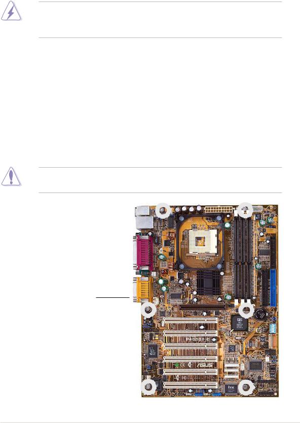
2.1.1 Placement direction
When installing the motherboard, make sure that you place it into the chassis in the correct orientation. The edge with external ports goes to the rear part of the chassis. Refer to the image below.
2.1.2 Screw holes
Place six (6) screws into the holes indicated by circles to secure the motherboard to the chassis.
Do not overtighten the screws! Doing so may damage the motherboard.
Place this side towards the rear of the chassis
ASUS P4S533-E motherboard user guide |
7 |
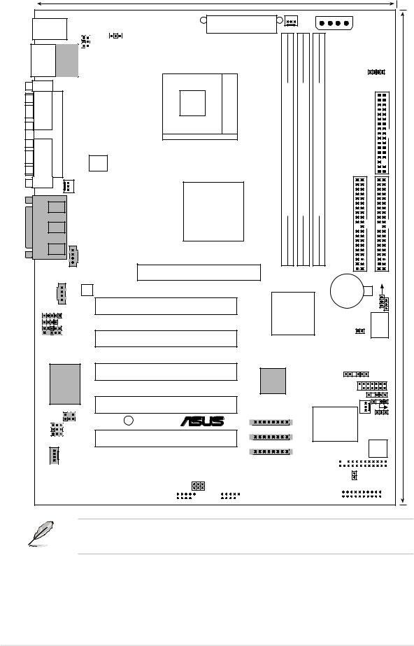
2.2Motherboard layout
|
|
|
|
21.9cm (8.6in) |
|
|
|
|
|
|
|
|
|
PS/2KBMS |
KBPWR USBV1 |
|
ATX Power Connector |
|
|
|
|
|
AUX12V1 |
||||
T: Mouse |
|
|
PWRFAN1 |
|
|
||||||||
B: Keyboard |
|
|
|
|
|
|
|
|
|
|
|
|
|
|
|
VEN1 |
|
|
|
|
|
|
|
|
|
|
|
Bottom: |
|
|
|
|
|
|
|
|
|
|
|
|
|
|
Top: |
|
|
|
|
|
|
|
|
|
|
|
|
USB1 RJ-45 |
|
|
|
|
|
|
|
|
|
|
|
|
|
USB2 |
|
|
|
|
|
|
|
|
|
DDRVOL1 |
|
||
COM1 |
|
|
|
Socket 478 |
DIMM1(64/72 bit, 184-pin module) |
DIMM2(64/72 bit, 184-pin module) |
DIMM3(64/72 bit, 184-pin module) |
|
|
|
|||
|
PARALLEL PORT |
ATX12V1 |
|
|
|
FLOPPY1 |
|||||||
|
|
|
|
|
|
|
|
|
|
|
|
|
|
COM2 |
|
|
|
|
|
|
|
|
|
|
|
|
|
|
CPUFAN1 |
|
SiS645DX |
|
|
|
|
|
|
|
|
|
|
AUDIOGAME |
|
|
|
DDR |
DDR |
DDR |
|
|
|
||||
Out |
|
|
HOST/ |
IDESECONDARY |
|
IDEPRIMARY |
|||||||
|
Line |
|
|
|
|
|
|
|
|
|
|
|
|
|
Line |
|
|
Memory |
|
|
|
|
|
|
|
|
|
|
|
|
Controller |
|
|
|
|
|
|
|
|
|
|
|
In |
|
|
|
|
|
|
|
|
|
|
|
|
|
Mic |
|
|
|
|
|
|
|
|
|
|
|
|
|
In |
|
|
|
|
|
|
|
|
|
|
|
|
|
|
AUX1 |
Accelerated Graphics Port |
0 |
1 |
2 |
3 |
4 |
5 |
|
|
|
|
|
|
|
|
|
|
|
|
|
|
|
|||
|
|
|
|
|
|
|
|
|
|
|
|
||
|
|
|
|
AGP |
|
|
|
|
|
|
|
CLRCMOS1 |
|
|
|
|
|
|
|
|
|
|
|
|
|
||
|
|
LAN PHY |
|
|
|
|
|
|
|
|
CR2032 3V |
|
JEN1 |
|
|
|
|
|
|
|
|
|
|
|
Lithium Cell |
|
|
|
|
|
|
|
SiS962 |
|
|
CMOS Power |
|||||
|
CD1 |
|
PCI1 |
|
|
|
|
|
|
||||
|
ALIN1 |
|
|
MuTLOL |
|
|
|
|
|
||||
|
|
|
|
Media |
|
|
|
|
DSW1 |
||||
|
ALOUT1 |
|
|
|
|
PWRTMP1 |
|||||||
|
|
|
I/O |
|
|
|
|
||||||
|
|
|
|
|
|
|
|
|
|
||||
|
IAPANEL1 |
|
|
|
|
|
|
|
|
|
|||
|
PCI2 |
|
|
|
|
|
|
|
|
|
|
||
|
|
|
|
|
|
|
|
|
|
|
|
|
|
|
Media-C CMI87386CH AudioController |
|
P4S533-E |
|
|
|
|
|
|
|
|
CHASSFAN1 |
|
|
|
PCI4 |
|
|
|
|
|
|
|
|
|
||
|
|
|
PCI3 |
|
RTL8801 |
|
|
|
|
|
SMB1 |
|
|
|
|
|
|
|
|
|
|
|
|
SMARTCON1 |
|
|
|
|
|
|
|
|
|
|
|
|
|
|
IR |
|
|
|
|
|
|
|
|
|
|
|
|
|
CHASFAN1 |
|
|
|
SPDIF1 |
|
|
|
|
|
|
|
|
ASUS |
SPEECH1 |
||
|
LED1 |
® |
|
|
|
|
|
|
ASIC |
||||
|
BCS1 |
|
|
|
|
|
|
|
|
with |
|
|
|
|
|
|
|
IEEE_1394_1 |
|
|
|
|
|
|
|
||
|
BCS2 |
|
PCI5 |
|
|
|
|
|
|
Hardware |
|
|
|
|
AEN1 |
|
|
|
|
|
|
|
|
Monitor |
|
|
|
|
|
|
|
IEEE_1394_2 |
|
|
|
|
|
|
|
|
|
|
|
|
|
|
|
|
|
|
|
|
|
SPEECH |
|
|
|
|
|
|
|
|
|
|
|
|
|
|
|
|
|
|
4Mbit Firmware Hub |
|
USBV2 |
|
|
|
|
|
|
|
Super |
|
|
|
|
|
|
|
|
|
|
|
|
|
|
|||||
|
|
|
|
|
|
|
|
|
|
|
|
|
|
|
|
|
|
IEEE_1394_3 |
AFPANEL1 |
|
|
|
|
|
|
|
|
|
|
|
|
|
MODEM1 |
|
|
PCI6 |
|
|
|
|
|
|
|
|
|
|
|
|
|
|
|
|
|
|
|
|
|||||||||
|
|
|
|
|
|
|
|
|
|
|
|
|
IDELED1 |
|
||||||||||||||||||
|
|
|
|
|
|
|
|
|
|
|
|
|
|
|
|
|
|
I/O |
|
|||||||||||||
|
|
|
|
|
USBV3 |
|
|
|
|
|
|
|
|
|||||||||||||||||||
|
|
|
|
|
|
|
|
|
|
|
|
PANEL1 |
|
|
|
|
|
|
|
|
|
|
|
|
||||||||
|
|
|
|
|
|
|
|
|
|
|
|
|
|
|
|
|
|
|
|
|
|
|
|
|||||||||
|
|
|
|
|
USB3 |
|
|
|
|
|
USB2 |
|
|
|
|
|
|
|
|
|
|
|
|
|
|
|
|
|
|
|
||
|
|
|
|
|
|
|
|
|
|
|
|
|
|
|
|
|
||||||||||||||||
The 1394 and LAN features are optional. These components are grayed out in the above motherboard layout.
30.5cm (12.0in)
8 |
Chapter 2: Hardware information |
2.2.1 Layout contents
CPU, Memory and Expansion Slots
1) |
Socket 478 |
p. 12 Installing the CPU |
|
2) |
Heatsink |
p. 14 Installing the Heatsink and Fan |
|
3) |
Memory |
p. 17 System Memory Support |
|
4) |
PCI 1/2/3/4/5/6 |
p. 21 32-bit PCI Bus Expansion Slots |
|
5) |
AGP 4x |
p. 23 Accelerated Graphics Slot |
|
Motherboard Settings (Switches and Jumpers) |
|||
1) |
JEN |
p. 24 |
JumperFree Mode Setting (Disable/Enable) |
2) |
DSW1-5 |
p. 25 |
Frequency Selection (Jumpers 1–5) |
3) |
USBV1, 2, 3 |
p. 26 |
USB Device Wake-up (+5V / +5VSB) |
4) |
DDRVOL1 |
p. 27 DDR Voltage Setting (2.5V, 2.7V, 2.9V) |
|
5) |
BCS1, BCS2 |
p. 27 |
Bass Center Setting (Bass Center/Center Bass) |
6) |
KBPWR1 |
p. 28 Keyboard Wake Up (+5V, +5VSB) |
|
7) |
VEN1 |
p. 28 CPU Voltage Setting (CPU + 0.2V, Normal) |
|
8) |
SPEECH |
p. 29 |
Speaker Selector (Buzzer / Lineout) |
9) |
CLRCMOS1 |
p. 30 Clear RTC RAM |
|
Connectors |
|
|
|
1) |
PS2KBMS |
p. 31 PS/2 Mouse Port (6 pin female) |
|
2) |
PS2KBMS |
p. 31 PS/2 Keyboard Port (6 pin female) |
|
3) |
USB |
p. 32 |
Universal Serial Bus Ports 0, 1, 2 & 3 (Two x 4 pin female) |
4) |
PRINTER |
p. 32 Parallel Port (25 pin female) |
|
5) |
COM1/ 2 |
p. 32 |
Serial Port (9 pin male) |
6) |
GAME_AUDIO |
p. 33 |
Game/MIDI Ports (Gold 15 pin) |
7) |
AUDIO |
p. 33 Audio Connectors (Three 1/8” AUDIO) |
|
8) |
RJ45 |
p. 33 |
Fast-Ethernet Port Connector (4 pin female) |
9) |
IDELED |
p. 34 IDE Activity LED (Two 40-1 pin) |
|
10) |
PRIMARY / SEC. IDE |
p. 35 IDE Connectors (Four 40-1 pin) |
|
11) |
FLOPPY |
p. 36 Floppy Disk Drive Connector (34-1 pin) |
|
12) |
PWR, CHA, CPUFAN1 |
p. 36 Power, Chassis and CPU Fan Connectors (Three 3 pin) |
|
13) |
ATXPWR |
p. 37 ATX Power Supply Connector (20 pin) |
|
14) |
USB2/3 |
p. 38 |
USB Headers (Two 10-1 pin) |
15) |
CD1, AUX1, MODEM |
p. 38 Internal Audio Connectors (Three 4-1 pin) (optional) |
|
16) |
SPDIF1 |
p. 39 |
Digital Audio Connector (4-1 pin) |
17) |
CHASSIS |
p. 39 |
Chassis Open Alarm Lead (4-1 pin) |
18) |
IR1 |
p. 40 |
Infrared module connector (5-1 pin) |
19) |
SMARTCON1 |
p. 40 |
Smart Card Reader Connector (14-1 pin) |
20) |
LINE_IN |
p. 41 Audio line-in header (5 pin) |
|
21) |
ALOUT1 |
p. 41 Audio Line-out Selector jumpers (4 pin) |
|
continued...
ASUS P4S533-E motherboard user guide |
9 |

22) |
IAPANEL1 |
p. 42 Front panel audio connector (10-1 pin) (optional) |
|
23) |
AFPANEL |
p. 42 ASUS iPanel / Infrared Connector (24-1 pin ) |
|
24) |
JTPWR |
p. 43 Power Supply Thermal Sensor Connector (2 pin) |
|
25) |
IEEE-1394_1, _2, _3 |
p. 43 IEEE-1394 Header (3x10 pin) |
|
26) |
PLED |
p. 44 System Power LED Lead (3-1 pin) |
|
27) |
SPEAKER |
p. 44 System Warning Speaker Lead (4 pin) |
|
28) |
MLED |
p. 44 |
System Message LED Lead (2 pin) |
29) |
SMI |
p. 44 |
System Management Interrupt Lead (2 pin) |
30) |
PWRSW |
p. 44 |
ATX Power Switch / Soft-Off Switch Lead (2 pin) |
31) |
RESET |
p. 44 |
Reset Switch Lead (2-pin) |
2.3Before you proceed
Take note of the following precautions before you install motherboard components or change any motherboard settings.
1. Unplug the power cord from the wall socket before touching any component.
2.Use a grounded wrist strap or touch a safely grounded object or to a metal object, such as the power supply case, before handling components to avoid damaging them due to static electricity.
3.Hold components by the edges and do not to touch the ICs on them.
4.Whenever you uninstall any component, place it on a grounded antistatic pad or in the bag that came with the component.
5.Before you install or remove any component, ensure that the ATX power supply is switched off or the power cord is detached from the power supply. Failure to do so may cause severe damage to the motherboard, peripherals, and/or components.
23.
10 |
Chapter 2: Hardware information |
2.4Central Processing Unit (CPU)
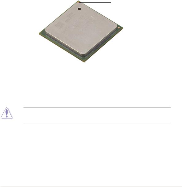
2.4.1 Overview
The motherboard comes with a surface mount 478-pin Zero Insertion Force (ZIF) socket. This socket is specifically designed for the Intel® Pentium® 4 478/Northwood Processor.
The Intel Pentium 4 Processor in the 478-pin package uses the Flip-Chip Pin Grid Array 2 (FC-PGA2) package technology, and includes the Intel® NetBurst™ micro-architecture. The Intel NetBurst micro-architecture features the hyper-pipelined technology, rapid execution engine, 400MHz system bus, and execution trace cache. Together, these attributes improve system performance by allowing higher processor frequencies, faster execution of integer instructions, and a data transfer rate of 3.2GB/s.
Gold Mark
Note in the illustration that the CPU has a gold triangular mark on one corner. This mark indicates the processor Pin 1 that should match a specific corner of the CPU socket.
Incorrect installation of the CPU into the socket may bend the pins and severely damage the CPU!
ASUS P4S533-E motherboard user guide |
11 |

2.4.2 Installing the CPU
Follow these steps to install a CPU.
1. Locate the 478-pin ZIF socket on the motherboard.
2.Unlock the socket by pressing the lever sideways, then lift it up to a 90°-100° angle.
Socket Lever
90 - 100
Make sure that the socket lever is lifted up to 90°-100° angle, otherwise the CPU does not fit in completely.
12 |
Chapter 2: Hardware information |
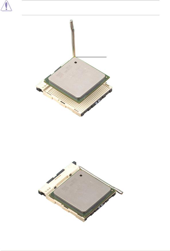
3.Position the CPU above the socket such that its marked corner matches the base of the socket lever.
4.Carefully insert the CPU into the socket until it fits in place.
The CPU fits only in one correct orientation. DO NOT force the CPU into the socket to prevent bending the pins and damaging the CPU!
Gold Mark
5.When the CPU is in place, press it firmly on the socket while you push down the socket lever to secure the CPU. The lever clicks on the side tab to indicate that it is locked.
ASUS P4S533-E motherboard user guide |
13 |
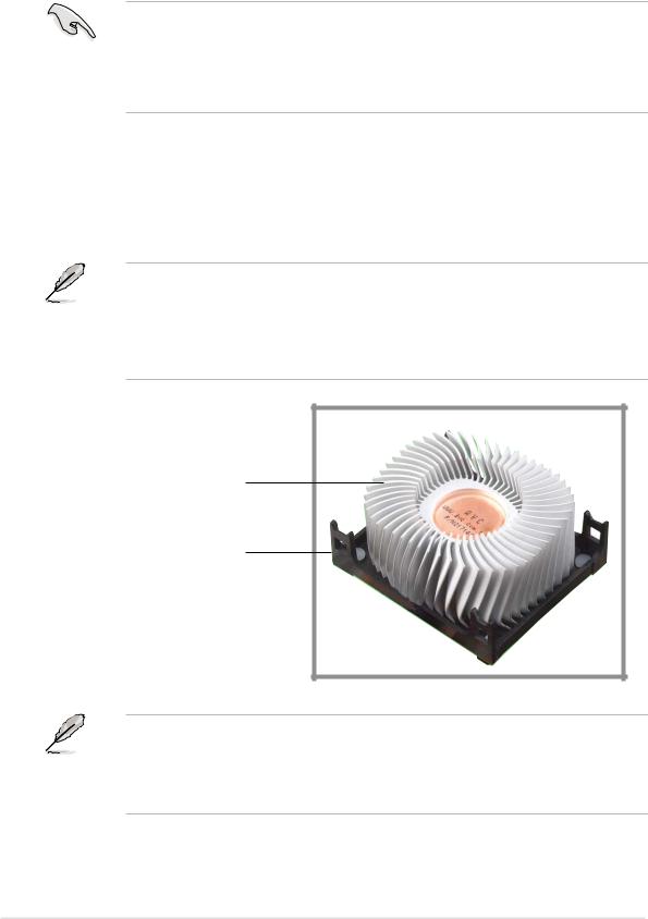
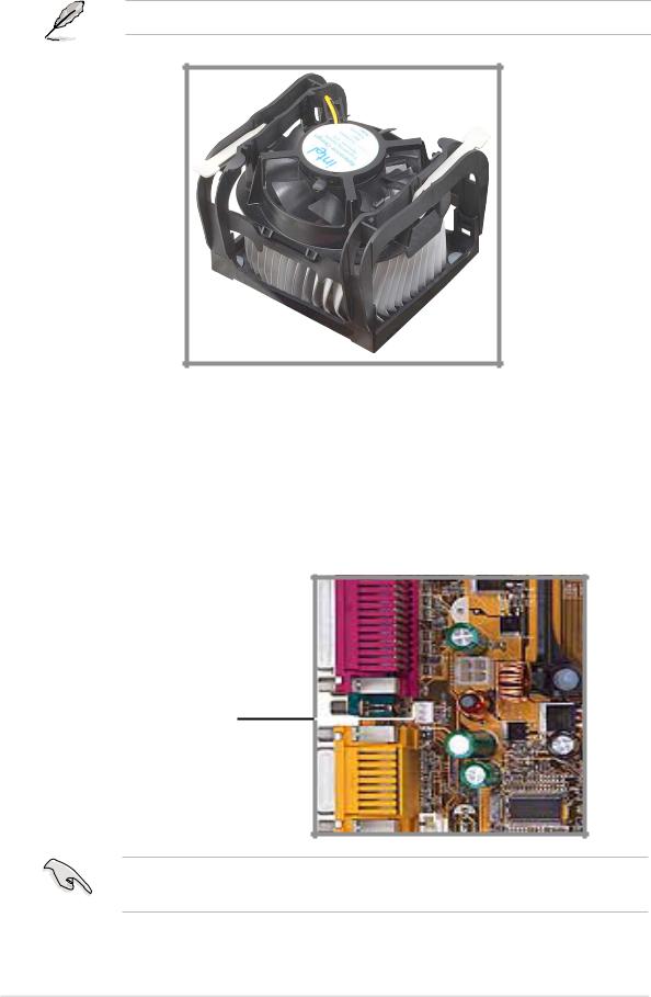
2.4.3 Installing the heatsink and fan
The Intel® Pentium® 4 478/Northwood Processor requires a specially designed heatsink and fan assembly to ensure optimum thermal condition and performance.
When you buy a boxed Intel Pentium 4 478/Northwood Processor, the package includes the heatsink, fan, and retention mechanism.
In case you buy a CPU separately, make sure that you use only Intel certified heatsink and fan.
Follow these steps to install the CPU heatsink and fan.
1.Place the heatsink on top of the installed CPU, making sure that the heatsink fits properly on the retention module base.
The retention module base is already installed on the motherboard upon purchase.
You do not have to remove the retention module base when installing the CPU or installing other motherboard components.
CPU Heatsink
Retention Module Base
Your boxed Intel Pentium 4 478/Northwood Processor package should come with installation instructions for the CPU, heatsink, and the retention mechanism. If the instructions in this section do not match the CPU documentation, follow the latter.
14 |
Chapter 2: Hardware information |
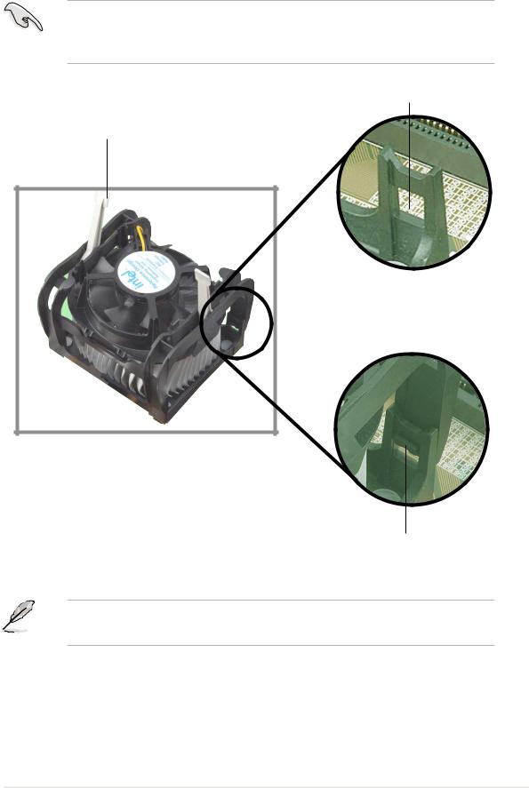
2.Position the fan with the retention mechanism on top of the heatsink. Align and snap the four hooks of the retention mechanism to the holes on each corner of the module base.
Make sure that the fan and retention mechanism assembly perfectly fits the heatsink and module base, otherwise you cannot snap the hooks into the holes.
Retention Hole
Retention Lock
Retention Hook Snapped to the Retention Hole
Keep the retention locks lifted upward while fitting the retention mechanism to the module base.
ASUS P4S533-E motherboard user guide |
15 |
3.Push down the locks on the retention mechanism to secure the heatsink and fan to the module base.
When secure, the retention locks should point to opposite directions.
2.4.4 Connecting the CPU fan cable
When the fan, heatsink, and the retention mechanism are in place, connect the CPU fan cable to the connector on the motherboard labeled CPUFAN1.
CPU Fan Connector (CPUFAN1)
Don’t forget to connect the CPU fan connector! Hardware monitoring errors may occur if you fail to plug this connector.
16 |
Chapter 2: Hardware information |
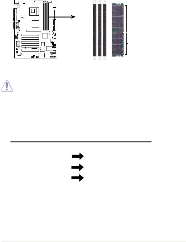
2.5System memory
2.5.1 Overview
The motherboard comes with three Double Data Rate (DDR) Dual Inline Memory Module (DIMM) sockets. These sockets support up to 3GB system memory using 184-pin unbuffered non-ECC PC2700/2100/1600 DIMMs. (Only 4 banks of PC2700 are supported.)
P4S533-E |
104 Pins
80 Pins
P4S533-E 184-Pin DDR DIMM Sockets
A DDR DIMM is keyed with a notch so that it fits in only one direction. DO NOT force a DIMM into a socket to avoid damaging the DIMM.
The DDR SDRAM technology evolved from the mainstream PC66, PC100, PC133 memory known as Single Data Rate (SDR) SDRAM. DDR memory however, has the ability to perform two data operations in one clock cycle, thus providing twice the throughput of SDR memory.
DDR Data Transfer Rate |
DDR Base Frequency |
2.7 GB/s |
166MHz |
|
|
2.1 GB/s |
133MHz |
|
|
1.6 GB/s |
100MHz |
|
|
A DDR DIMM has the same physical dimensions as an SDR DIMM, but it has a 184-pin footprint compared to the 168-pin of the SDR DIMM. Also, a DDR DIMM is single notched while an SDR DIMM is double notched.
Therefore, a DDR DIMM is not backward compatible with SDR, and should be installed only in a socket specially designed for DDR DIMMs.
ASUS P4S533-E motherboard user guide |
17 |

2.5.2 Memory configurations
You may install any DDR DIMMs with 64MB, 128MB, 256MB, 512MB, and 1GB densities into the three DIMM sockets.
Use the following three combinations to install DDR DIMMs.
DIMM Location |
184-pin DDR DIMM |
|
Total Memory |
Socket 1 (Rows 0&1) 64MB, 128MB, 256MB, 512MB, 1GB |
x1 |
= |
|
|
|
|
|
Socket 2 (Rows 2&3) 64MB, 128MB, 256MB, 512MB, 1GB |
x1 |
= |
|
|
|
|
|
Socket 3 (Rows 4&5) 64MB, 128MB, 256MB, 512MB, 1GB |
x1 |
= |
|
|
|
|
|
Total system memory (Max. 3GB) |
|
= |
|
|
|
|
|
DDR333 DIMM Qualified Vendor List
The following table lists the DDR333 memory modules that have been tested and qualified for use with this motherboard.
Vendor |
Model |
Type/Size |
Nanya |
NT5DS16M8AT-6 |
PC2700/256MB |
|
|
|
Samsung |
K4H280838D-TCB3 |
PC2700/128MB |
|
|
|
Samsung |
K4H280838D-TCB3 |
PC2700/256MB |
|
|
|
Micron |
MT8VDDT1664AG-335B1 |
PC2700/128MB |
|
|
|
Micron |
MT16VDDT3264AG-335B1 |
PC2700/256MB |
|
|
|
KINGMAX |
MPMA82D-68KX3 |
PC2700/128MB |
|
|
|
KINGMAX |
MPM62D-68KX3 |
PC2700/256MB |
|
|
|
Use only the tested and qualified DDR333 DIMMs listed above. Other DDR DIMMs manufactured by other vendors may not be suitable for this motherboard. Visit the ASUS website for the latest qualified DDR module list.
18 |
Chapter 2: Hardware information |
 Loading...