


 Loading...
P2-P5N9300/P4-P5N9300
ASUS PC (Desktop Barebone)
User Manual

E4224
First Edition V1
March 2009
Copyright © 2009 ASUSTeK Computer Inc. All Rights Reserved.
No part of this manual, including the products and software described in it, may be reproduced, transmitted, transcribed, stored in a retrieval system, or translated into any language in any form or by any means, except documentation kept by the purchaser for backup purposes, without the express written permission of ASUSTeK Computer Inc. (“ASUS”).
Product warranty or service will not be extended if: (1) the product is repaired, modified or altered, unless such repair, modification of alteration is authorized in writing by ASUS; or (2) the serial number of the product is defaced or missing.
ASUS PROVIDES THIS MANUAL “AS IS” WITHOUT WARRANTY OF ANY KIND, EITHER EXPRESS OR IMPLIED, INCLUDING BUT NOT LIMITED TO THE IMPLIED WARRANTIES OR CONDITIONS OF MERCHANTABILITY OR FITNESS FOR A PARTICULAR PURPOSE. IN NO EVENT SHALL ASUS, ITS DIRECTORS, OFFICERS, EMPLOYEES OR AGENTS BE LIABLE FOR ANY INDIRECT, SPECIAL, INCIDENTAL, OR CONSEQUENTIAL DAMAGES (INCLUDING DAMAGES FOR LOSS OF PROFITS, LOSS OF BUSINESS, LOSS OF USE OR DATA, INTERRUPTION OF BUSINESS AND THE LIKE), EVEN IF ASUS HAS BEEN ADVISED OF THE POSSIBILITY OF SUCH DAMAGES ARISING FROM ANY DEFECT OR ERROR IN THIS MANUAL OR PRODUCT.
SPECIFICATIONS AND INFORMATION CONTAINED IN THIS MANUAL ARE FURNISHED FOR INFORMATIONAL USE ONLY, AND ARE SUBJECT TO CHANGE AT ANY TIME WITHOUT NOTICE, AND SHOULD NOT BE CONSTRUED AS A COMMITMENT BY ASUS. ASUS ASSUMES NO RESPONSIBILITY OR LIABILITY FOR ANY ERRORS OR INACCURACIES THAT MAY APPEAR IN THIS MANUAL, INCLUDING THE PRODUCTS AND SOFTWARE DESCRIBED IN IT.
Products and corporate names appearing in this manual may or may not be registered trademarks or copyrights of their respective companies, and are used only for identification or explanation and to the owners’ benefit, without intent to infringe.
ii

Table of contents
Notices......................................................................................................... |
vi |
Safety information...................................................................................... |
vii |
About this guide........................................................................................ |
viii |
System package contents........................................................................... |
x |
Chapter 1: |
System introduction |
|
|
1.1 |
Welcome! |
....................................................................................... |
1-2 |
1.2 |
Front panel.................................................................................... |
1-2 |
|
1.3 |
Rear panel..................................................................................... |
1-4 |
|
1.4 |
Internal components.................................................................... |
1-6 |
|
Chapter 2: |
Starting up |
|
|
2.1 |
Installing an operating system.................................................... |
2-2 |
|
2.2 |
Powering up your system............................................................ |
2-2 |
|
2.3 |
Support CD information............................................................... |
2-3 |
|
|
2.3.1 |
Running the Support CD................................................. |
2-3 |
|
2.3.2 |
Drivers menu................................................................... |
2-4 |
|
2.3.3 |
Utilities menu................................................................... |
2-5 |
|
2.3.4 |
Make Disk menu.............................................................. |
2-6 |
|
2.3.5 |
Manual menu................................................................... |
2-7 |
|
2.3.6 |
ASUS Contact information............................................... |
2-7 |
|
2.3.7 |
Other information............................................................. |
2-8 |
2.4 |
ASUS AI Manager........................................................................ |
2-10 |
|
|
2.4.1 |
Installing AI Manager..................................................... |
2-10 |
|
2.4.2 |
Launching AI Manager................................................... |
2-10 |
|
2.4.3 |
AI Manager Quick Bar................................................... |
2-10 |
|
2.4.4 |
Main................................................................................ |
2-11 |
|
2.4.5 |
My favorites................................................................... |
2-14 |
|
2.4.6 |
Support.......................................................................... |
2-15 |
|
2.4.7 |
Information..................................................................... |
2-15 |
Chapter 3: |
Motherboard info |
|
|
3.1 |
Introduction................................................................................... |
3-2 |
|
3.2 |
Motherboard layout...................................................................... |
3-2 |
|
3.3 |
Jumpers |
......................................................................................... |
3-3 |
3.4 |
Connectors.................................................................................... |
3-6 |
|
iii

Table of contents
Chapter 4: |
BIOS setup |
|
|
4.1 |
Managing and updating you BIOS.............................................. |
4-2 |
|
|
4.1.1 |
Creating a bootable floppy disk....................................... |
4-2 |
|
4.1.2 |
AwardBIOS flash utility.................................................... |
4-3 |
|
4.1.3 |
ASUS CrashFree BIOS 2 utility....................................... |
4-6 |
|
4.1.4 |
ASUS EZ Flash 2 utility................................................... |
4-8 |
|
4.1.5 |
ASUS Update utility......................................................... |
4-9 |
4.2 |
BIOS setup program................................................................... |
4-12 |
|
|
4.2.1 |
BIOS menu screen........................................................ |
4-13 |
|
4.2.2 |
Menu bar....................................................................... |
4-13 |
|
4.2.3 |
Legend bar.................................................................... |
4-14 |
|
4.2.4 |
Menu items.................................................................... |
4-14 |
|
4.2.5 |
Submenu items.............................................................. |
4-14 |
|
4.2.6 |
Configuration fields........................................................ |
4-14 |
|
4.2.7 |
Pop-up window.............................................................. |
4-15 |
|
4.2.8 |
General help.................................................................. |
4-15 |
4.3 |
Main menu................................................................................... |
4-16 |
|
|
4.3.1 |
System Time.................................................................. |
4-16 |
|
4.3.2 |
System Date.................................................................. |
4-16 |
|
4.3.3 |
SATA1-2.......................................................................................... |
4-17 |
|
4.3.4 |
ESATA............................................................................ |
4-18 |
|
4.3.5 |
HDD SMART Monitoring................................................ |
4-18 |
4.4 |
Advanced menu.......................................................................... |
4-19 |
|
|
4.4.1 |
JumperFree Configuration............................................. |
4-19 |
|
4.4.2 |
CPU Configuration......................................................... |
4-23 |
|
4.4.3 |
Chipset.......................................................................... |
4-24 |
|
4.4.4 |
PCIPnP.......................................................................... |
4-25 |
|
4.4.5 |
Onboard Device Configuration...................................... |
4-26 |
|
4.4.6 |
USB Configuration......................................................... |
4-28 |
4.5 |
Power menu................................................................................ |
4-29 |
|
|
4.5.1 |
ACPI Suspend Type...................................................... |
4-29 |
|
4.5.2 |
ACPI APIC Support....................................................... |
4-29 |
|
4.5.3 |
APM Configuration........................................................ |
4-30 |
|
4.5.4 |
Hardware Monitor.......................................................... |
4-32 |
iv

Table of contents
4.6 |
Boot menu................................................................................... |
4-33 |
|
|
4.6.1 |
Boot Device Priority....................................................... |
4-33 |
|
4.6.2 |
Boot Settings Configuration .......................................... |
4-34 |
|
4.6.3 |
Security.......................................................................... |
4-35 |
4.7 |
Tools menu.................................................................................. |
4-37 |
|
|
4.7.1 |
ASUS EZ Flash 2.......................................................... |
4-37 |
|
4.7.2 |
Express Gate................................................................. |
4-38 |
4.8 |
Exit menu..................................................................................... |
4-39 |
|
Notices
ASUS REACH
Complying with the REACH (Registration, Evaluation, Authorisation, and Restriction of Chemicals) regulatory framework, we published the chemical substances in our products at ASUS REACH website at http://green.asus.com/ english/REACH.htm.
Federal Communications Commission Statement
This device complies with Part 15 of the FCC Rules. Operation is subject to the following two conditions:
•This device may not cause harmful interference; and
•This device must accept any interference received including interference that may cause undesired operation.
This equipment has been tested and found to comply with the limits for a Class B digital device, pursuant to Part 15 of the FCC Rules. These limits are designed to provide reasonable protection against harmful interference in a residential installation. This equipment generates, uses and can radiate radio
frequency energy and, if not installed and used in accordance with manufacturer’s instructions, may cause harmful interference to radio communications. However, there is no guarantee that interference will not occur in a particular installation. If this equipment does cause harmful interference to radio or television reception, which can be determined by turning the equipment off and on, the user is encouraged to try to correct the interference by one or more of the following measures:
•Reorient or relocate the receiving antenna.
•Increase the separation between the equipment and receiver.
•Connect the equipment to an outlet on a circuit different from that to which the receiver is connected.
•Consult the dealer or an experienced radio/TV technician for help.
The use of shielded cables for connection of the monitor to the graphics card is required to assure compliance with FCC regulations. Changes or modifications to this unit not expressly approved by the party responsible for compliance could void the user’s authority to operate this equipment.
Canadian Department of Communications Statement
This digital apparatus does not exceed the Class B limits for radio noise emissions from digital apparatus set out in the Radio Interference Regulations of the Canadian Department of Communications.
This class B digital apparatus complies with Canadian ICES-003.
vi

Macrovision Corporation Product Notice
This product incorporates copyright protection technology that is protected by U.S. patents and other intellectual property rights. Use of this copyright protection technology must be authorized by Macrovision, and is intended for home and other limited viewing uses only unless otherwise authorized by Macrovision. Reverse engineering or disassembly is prohibited.
Safety information
Electrical safety
•To prevent electric shock hazard, disconnect the power cable from the electric outlet before relocating the system.
•When adding or removing any devices to or from the system, contact a qualified service technician or your retailer. Ensure that all the power cables for the devices are unplugged before the signal cables are connected. If possible, disconnect all the power cables from the existing system before you add or remove a device to or from the system.
•If the power supply is broken, do not try to fix it by yourself. Contact a qualified service technician or your retailer.
Operation safety
•Before installing devices into the system, carefully read all the documentation that comes with the package.
•Before using the product, ensure that all the cables are correctly connected and the power cables are not damaged. If you detect any damage, contact your dealer immediately.
•To avoid short circuits, keep paper clips, screws, and staples away from connectors, slots, sockets, and circuitry.
•Avoid dust, humidity, and temperature extremes. Do not place the product in any area where it may become wet. Place the product on a flat and stable surface.
•Do not block the air vents on the chassis. Always provide proper ventilation for this product.
•We recommend that you use this product in environments with an ambient temperature below 40˚C.
•If you encounter technical problems with this product, contact a qualified service technician or your retailer.
vii

Lithium-Ion Battery Warning
CAUTION: Danger of explosion if battery is incorrectly replaced. Replace only with the same or equivalent type recommended by the manufacturer.
Dispose of used batteries according to the manufacturer’s instructions.
VORSICHT: Explosionsgetahr bei unsachgemäßen Austausch der Batterie.
Ersatz nur durch denselben oder einem vom Hersteller empfohlenem
ähnljchen Typ. Entsorgung gebrauchter Batterien nach Angaben des Herstellers.
LASER PRODUCT WARNING
 CLASS 1 LASER PRODUCT
About this guide
Audience
This guide provides general information about the ASUS P2-P5N9300/ P4-P5N9300 barebone system. This guide is intended for experienced users and integrators with hardware knowledge of personal computers.
How this guide is organized
This guide contains the following parts:
1.Chapter 1: System introduction
This chapter gives a general description of ASUS P2-P5N9300/P4-P5N9300.
The chapter lists the system features, including introduction on the front and rear panel, and internal components.
2.Chapter 2: Starting up
This chapter helps you power up the system and install drivers and utilities from the support CD.
3.Chapter 3: Motherboard information
This chapter gives information about the motherboard that comes with the system. This chapter includes the motherboard layout, jumper settings, and connector locations.
4.Chapter 4: BIOS information
This chapter tells how to change system settings through the BIOS Setup menus and describes the BIOS parameters.
viii

Conventions used in this guide
To ensure that you perform certain tasks properly, take note of the following symbols used throughout this manual.
WARNING: Information to prevent injury to yourself when trying to complete a task.
CAUTION: Information to prevent damage to the components when trying to complete a task.
IMPORTANT: Instructions that you MUST follow to complete a task.
NOTE: Tips and additional information to help you complete a task.
Where to find more information
Refer to the following sources for additional information and for product and software updates.
1.ASUS Websites
The ASUS websites provide updated information on ASUS hardware and software products. Refer to the ASUS contact information.
2.Optional Documentation
Your product package may include optional documentation, such as warranty flyers, that may have been added by your dealer. These documents are not part of the standard package.
ix
System package contents
Check your P2-P5N9300/P4-P5N9300 system package for the following items.
Standard items
1.ASUS P2-P5N9300/P4-P5N9300 barebone system with
•ASUS motherboard
•3-in-1 storage card reader
•PCIE raiser card
•200W power supply unit
2.Cables
•Power cable
•Serial ATA power cable and signal cable
3.CD
•Support CD
4.Quick Installation Guide
If any of the items is damaged or missing, contact your retailer immediately.
Optional items
1.ASUS VGA card
2.Infrared card (for P4-P5N9300 only)
3.Remote control (for P4-P5N9300 only)
Optional items are not included in the system package. They are purchased separately.
Chapter 1
This chapter gives a general description of ASUS P2-P5N9300/ P4-P5N9300. The chapter lists the system features including introduction on the front and rear panels, and internal components.
System introduction
ASUS P2-P5N9300/P4-P5N9300
1.1Welcome!
Thank you for purchasing the ASUS P2-P5N9300/P4-P5N9300!
The ASUS P2-P5N9300/P4-P5N9300 is an all-in-one barebone system with rich
home entertainment features.
The system comes in a stylish casing and powered by an ASUS motherboard that supports the Intel® Prescott, Smithfield, Cedarmill, Kentsfield, Conroe, Wolfdale, and Yorkfield processors.
The system supports up to 4GB system memory using unbuffered non-ECC DDR2 800/667MHz DIMMs, high-resolution graphics via integrated graphics controller, Serial ATA, USB 2.0, and eight-channel high-definition audio CODEC.
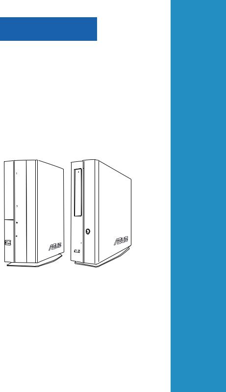
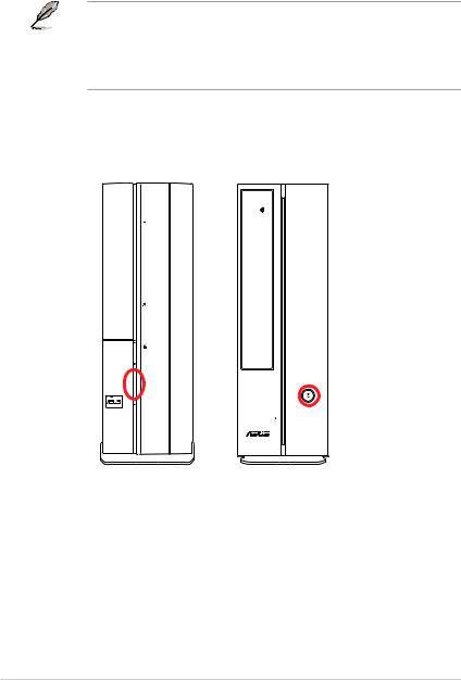
1.2Front panel
The illustrations below show the front panels of the P2-P5N9300 and P4-P5N9300.
Front panel of P2-P5N9300
1
2
3 |
6 |
|
4 |
7 |
8 |
5
9 |
|
10 |
11 |
12 |
Front panel (close) |
Front panel (open) |
1-2 |
Chapter 1: System introduction |
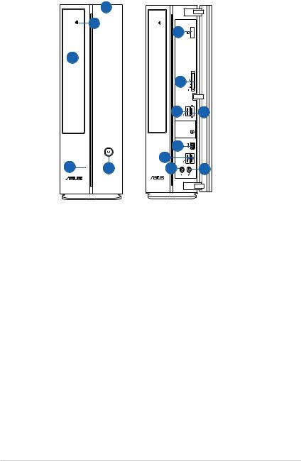
Front panel of P4-P5N9300
|
3 |
|
|
|
4 |
13 |
|
|
|
|
|
2 |
|
|
|
|
|
6 |
|
|
|
7 |
8 |
|
|
9 |
|
1 |
5 |
10 |
|
12 |
11 |
Front panel (close) |
Front panel (open) |
1.Hard disk drive (HDD) LED. This LED lights up when data is read from or written to the hard disk drive.
2.Optical disk drive (ODD) bay cover.
3.Front panel cover.
4. Optical disk drive eject button. Press this button to eject an optical disk.
5.Power button. Press this button to turn the system on.
6.3-in-1 card reader. This 3-in-1 card reader supports the MultiMediaCard,
Secure Digital™ card, and Memory Stick™/Memory Stick PRO™ card.
7.USB 2.0 port 9. This Universal Serial Bus 2.0 (USB 2.0) port connects to USB 2.0 devices such as a mouse, printer, scanner, camera, PDA, and others.
8.USB / eSATA port. This port connects to a USB 2.0 device or an external
Serial ATA hard disk drive.
9.4-pin IEEE 1394 port. This port connects to an IEEE 1394 device such as a digital camrecorder.
10.USB 2.0 ports 10 and 11. These Universal Serial Bus 2.0 (USB 2.0) ports connect to USB 2.0 devices such as a mouse, printer, scanner, camera, PDA, and others.
11.Microphone port (pink). This port connects to a microphone.
ASUS P2-P5N9300/P4-P5N9300 |
1-3 |
12.Headphone port (lime). This port connects to a headphone or speaker.
13.IR card (optional). This IR card supports a remote control.
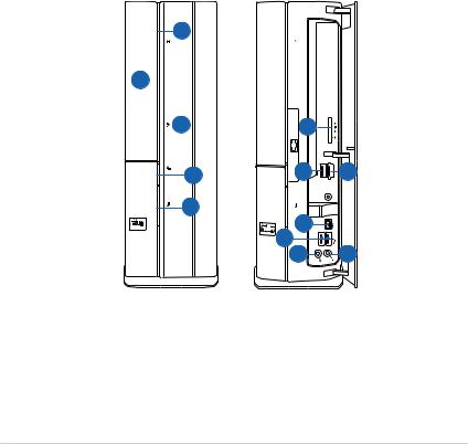
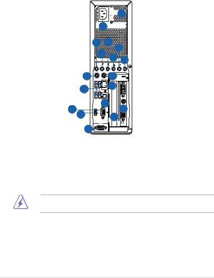
1.3Rear panel
The illustration below shows the rear panel of the P2-P5N9300 and P4-P5N9300.


 2
2


 1
1


8 |
|
6 |
4 |
|
7 |
|
|
|
5 |
3 |
|
|
|
||
|
|
|
|
10 |
9 |
|
12 |
11 |
|
|
|
|
|
13 |
14 |
15 |
17 |
|
|
18 |
|
16 |
|
|
|
Rear panel |
1.Power connector.
2.Voltage selector. This switch allows you to adjust the system input voltage according to the voltage supply in your area. If the voltage supply in your area is 100-127V, set this switch to 115V. If the voltage supply in your area is 200-240V, set this switch to 230V.
Setting the switch to 115V in a 230V environment or 230V in a 115 environment will seriously damage the system!
3.Center/Subwoofer port (orange). This port connects to the center/ subwoofer speakers.
4.Rear Speaker Out port (black). This port connects to the rear speakers in a
4-channel, 6-channel, or 8-channel audio configuration.
1-4 |
Chapter 1: System introduction |
5.Side Speaker Out port (grey). This port connects to the side speakers in an
8-channel audio configuration.
6.Line In port (light blue). This port connects to the tape, CD, DVD player, or other audio sources.
7.Line Out port (lime). This port connects to a headphone or speaker. In
4-channel, 6-channel, and 8-channel configurations, the function of this port becomes Front Speaker Out.
8.Microphone port (pink). This port connects to a microphone.
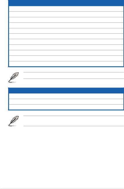
Refer to the audio configuration table below for the function of the audio ports in 2, 4, 6, or 8-channel configuration.
Audio 2, 4, 6, or 8-channel configuration
Port |
Headset |
4-channel |
6-channel |
8-channel |
|
2-channel |
|||||
|
|
|
|
||
Light Blue |
Line In |
Line In |
Line In |
Line In |
|
Lime |
Line Out |
Front Speaker Out |
Front Speaker Out |
Front Speaker Out |
|
Pink |
Mic In |
Mic In |
Mic In |
Mic In |
|
Orange |
– |
– |
Center/Subwoofer |
Center/Subwoofer |
|
Black |
– |
Rear Speaker Out |
Rear Speaker Ou |
Rear Speaker Out |
|
Gray |
– |
– |
– |
Side Speaker Out |
9.PS/2 mouse port (green). This port connects to a PS/2 mouse.
10.PS/2 keyboard port (purple). This port connects to a PS/2 keyboard.
11.LAN (RJ-45) port. This port allows Gigabit connection to a Local Area Network (LAN) through a network hub.
LAN port LED indications
ACT/LINK LED |
SPEED LED |
ACT/LINK |
SPEED |
||||||||
|
LED |
LED |
|||||||||
Status |
Description |
Status |
Description |
|
|
|
|
|
|
|
|
|
|
|
|
|
|
|
|
||||
OFF |
No link |
OFF |
10Mbps connection |
|
|
|
|
|
|
|
|
YELLOW |
Linked |
ORANGE |
100Mbps connection |
|
LAN port |
|
|||||
BLINKING |
Data activity |
GREEN |
1Gbps connection |
|
|
|
|
|
|
|
|
12.USB 2.0 ports 1, 2, 3, and 4. These 4-pin Universal Serial Bus (USB) ports connect to USB 2.0 devices such as a mouse, printer, scanner, camera, PDA, and others.
ASUS P2-P5N9300/P4-P5N9300 |
1-5 |
13.Optical S/PDIF_OUT port. This port connects to an external audio output device via an optical S/PDIF cable.
14.VGA port. This port connects to a VGA monitor or other VGA-compatible devices.
15.HDMI port. This port is for a High-Definition Multimedia Interface (HDMI) connector, and is HDCP compliant allowing playback of HD DVD, Blu-Ray discs, and other protected content.
16.Serial port. This port is for pointing devices or other serial devices.
17.ASUS VGA card (optional).
18.Expansion slot.
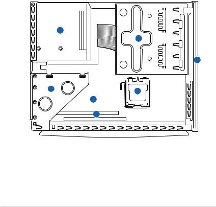
1.4Internal components
The illustration below is the internal view of the ASUS P2-P5N9300/P4-P5N9300 when you remove the chassis cover. The installed components are labeled for your reference.
3
1
2
4 |
7 |
|
|
|
5 |
|
6 |
1. |
5.25 inch optical disk drive and |
5. |
ASUS motherboard |
|
3.5 inch hard disk drive cage |
6. |
DIMM slots |
2. |
Front panel assembly |
7. |
LGA775 socket |
3.Power supply unit
4.PCIE raiser bracket (connected to the motherboard PCIE slot)
1-6 |
Chapter 1: System introduction |
Chapter 2
This chapter helps you power up the system and install drivers and utilities from the Support CD.
Starting up
ASUS P2-P5N9300/P4-P5N9300
2.1Installing an operating system
The ASUS P2-P5N9300/P4-P5N9300 supports Windows® XP / Vista Operating Systems (OS). Always install the latest OS version and corresponding updates to maximize the features of your hardware.
• To ensure that the OS work properly, install the drivers included in the Support CD.
•Motherboard settings and hardware options vary. Use the setup procedures presented in this chapter for reference only. Refer to your OS documentation for detailed information.
2.2Powering up your system
Press the power button ( ) to power up the system.
P2-P5N9300 |
P4-P5N9300 |
2-2 |
Chapter 2: Starting up |
2.3Support CD information
The support CD that comes with the system package contains the drivers, software applications, and utilities that you can install to get all the system features.
The contents of the Support CD are subject to change at any time without notice. Visit the ASUS website at www.asus.com for updates.
2.3.1Running the Support CD
Place the Support CD into the optical drive. The CD automatically displays the Drivers menu if Autorun is enabled on your computer.
Click an icon to display Support CD/motherboard information
Click an item to install
If Autorun is NOT enabled on your computer, browse the contents of the Support CD to locate the ASSETUP.EXE file from the BIN folder. Double-click the ASSETUP.EXE file to run the CD.
ASUS P2-P5N9300/P4-P5N9300 |
2-3 |

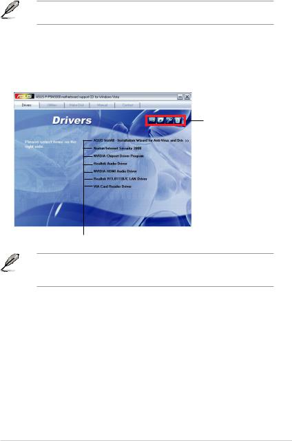
2.3.2Drivers menu
The Drivers menu shows the available device drivers if the system detects installed devices. Install the necessary drivers to activate the devices.
ASUS InstALL - Installation Wizard for Anti-Virus and Drivers Utility
Installs all of the drivers.
Norton Internet Security 2008
Installs Norton Internet Security 2008.
NVIDIA Chipset Driver Program
Installs the NVIDIA chipset driver program.
Realtek Audio Driver
Installs the Realtek® audio driver.
NVIDIA HDMI Audio Driver
Installs the NVIDIA HDMI audio driver.
Realtek RTL8111B/C LAN Driver
Installs the Realtek® RTL8111B/C LAN driver.
VIA Card Reader Driver
Installs the VIA® card reader driver.
2-4 |
Chapter 2: Starting up |
2.3.3Utilities menu
The Utilities menu shows the applications that the motherboard supports.
ASUS InstAll - Installation Wizard for Utilities
Installs all of the utilities.
ASUS Update
The ASUS Update utility allows you to update the motherboard BIOS in a Windows® environment. This utility requires an Internet connection either through a network or an Internet Service Provider (ISP).
ASUS Screen Saver
Installs the ASUS screensaver.
ASUS AI Manager
Installs the ASUS AI Manager where you can launch AI disk, AI Security, and AI Probe easily.
Acrobat Reader 8
Installs the Adobe® Acrobat® Reader that allows you to open, view, and print documents in Portable Document Format (PDF).
ASUS Express Gate Installer
Installs the ASUS Express Gate.
FarStone Utility
Installs the FarStone utility.
ASUS P2-P5N9300/P4-P5N9300 |
2-5 |

2.3.4Make Disk menu
The Make Disk menu allows you to make a RAID driver disk.
NVIDIA 32bit/64bit XP SATA RAID Driver
Allows you to create an NVIDIA® Serial ATA (SATA) RAID driver disk for 32bit/64bit
Windows® XP operating systems.
NVIDIA 32bit/64bit Vista SATA RAID Driver
Allows you to create an NVIDIA® Serial ATA (SATA) RAID driver disk for 32bit/64bit
Windows® Vista operating systems.
NVIDIA 32bit/64bit XP AHCI Driver
Allows you to create an NVIDIA® AHCI driver disk for 32bit/64bit Windows® XP operating systems.
NVIDIA 32bit/64bit Vista AHCI Driver
Allows you to create an NVIDIA® AHCI driver disk for 32bit/64bit Windows® Vista operating systems.
2-6 |
Chapter 2: Starting up |
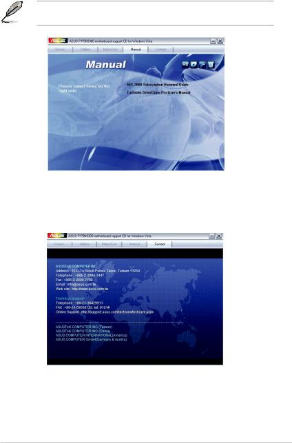
2.3.5Manual menu
The Manual menu contains a list of supplementary user manuals.
The manuals are in Portable Document Format (PDF) format. Install the Adobe® Acrobat® Reader from the Utilities menu before opening a manual.
2.3.6ASUS Contact information
Click the Contact tab to display the ASUS contact information.
ASUS P2-P5N9300/P4-P5N9300 |
2-7 |
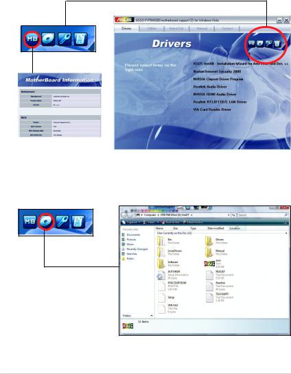
2.3.7Other information
The icons on the top right corner of the screen give additional information on the motherboard and the contents of the Support CD. Click an icon to display the specified information.
Motherboard Info
Displays the general specifications of the motherboard.
Browse this CD
Displays the Support CD contents in graphical format.
2-8 |
Chapter 2: Starting up |

Technical Support Form
Displays the ASUS Technical Support Request Form that you have to fill out when requesting technical support.
Filelist
Displays the contents of the Support CD and a brief description of each item in text format.
ASUS P2-P5N9300/P4-P5N9300 |
2-9 |
Loading...