


 Loading...
M2R-FVMMotherboard
E2614

First
 Edition

May 2006
Copyright © 2006 ASUSTeK COMPUTER INC.

 All
All
 Rights Reserved.
No part of this manual, including the products and software described in it, may be reproduced, transmitted, transcribed, stored in a retrieval system, or translated into any language in any form or by any means, except documentation kept by the purchaser for backup purposes, without the express written permission of ASUSTeK COMPUTER INC. (“ASUS”).
Product warranty or service will not be extended if: (1) the product is repaired, modified or altered, unless such repair, modification of alteration is authorized in writing by ASUS; or (2) the serial number of the product is defaced or missing.
ASUS PROVIDES THIS MANUAL “AS IS” WITHOUT WARRANTY OF ANY KIND, EITHER EXPRESS OR IMPLIED, INCLUDING BUT NOT LIMITED TO THE IMPLIED WARRANTIES OR CONDITIONS OF MERCHANTABILITY OR FITNESS FOR A PARTICULAR PURPOSE. IN NO EVENT SHALL ASUS, ITS DIRECTORS, OFFICERS, EMPLOYEES OR AGENTS BE LIABLE FOR ANY INDIRECT, SPECIAL,
INCIDENTAL, OR CONSEQUENTIAL DAMAGES (INCLUDING DAMAGES FOR LOSS OF PROFITS, LOSS OF BUSINESS, LOSS OF USE OR DATA, INTERRUPTION OF BUSINESS AND THE LIKE), EVEN IF ASUS HAS BEEN ADVISED OF THE POSSIBILITY OF SUCH DAMAGES ARISING FROM ANY DEFECT OR ERROR IN THIS MANUAL OR PRODUCT.
SPECIFICATIONS AND INFORMATION CONTAINED IN THIS MANUAL ARE FURNISHED FOR INFORMATIONAL USE ONLY, AND ARE SUBJECT TO CHANGE AT ANY TIME WITHOUT NOTICE, AND SHOULD NOT BE CONSTRUED AS A COMMITMENT BY ASUS. ASUS ASSUMES NO RESPONSIBILITY OR LIABILITY FOR ANY ERRORS OR INACCURACIES THAT MAY APPEAR IN THIS MANUAL, INCLUDING THE PRODUCTS AND SOFTWARE DESCRIBED IN IT.
Products and corporate names appearing in this manual may or may not be registered trademarks or copyrights of their respective companies, and are used only for identification or explanation and to the ownersʼ benefit, without intent to infringe.
ii


Contents
Notices............................................................................................... |
vii |
Safety information ............................................................................. |
viii |
About this guide.................................................................................. |
ix |
M2R-FVM specifications summary....................................................... |
xi |
Chapter 1: |
Product introduction |
|
|
1.1 |
Welcome!.............................................................................. |
1-1 |
|
1.2 |
Package contents ................................................................. |
1-1 |
|
1.3 |
Special features.................................................................... |
1-2 |
|
|
1.3.1 |
Product highlights................................................... |
1-2 |
|
1.3.2 |
Innovative ASUS features ...................................... |
1-4 |
1.4 |
Before you proceed .............................................................. |
1-5 |
|
1.5 |
Motherboard overview.......................................................... |
1-6 |
|
|
1.5.1 |
Placement direction ................................................ |
1-6 |
|
1.5.2 |
Screw holes............................................................. |
1-6 |
|
1.5.3 |
Motherboard layout ................................................ |
1-7 |
|
1.5.4 |
Layout contents ..................................................... |
1-8 |
1.6 |
Central Processing Unit (CPU) .............................................. |
1-9 |
|
|
1.6.1 |
Installing the CPU.................................................... |
1-9 |
|
1.6.2 Installing the heatsink and fan.............................. |
1-11 |
|
1.7 |
System memory.................................................................. |
1-14 |
|
|
1.7.1 |
Overview............................................................... |
1-14 |
|
1.7.2 |
Memory configurations ......................................... |
1-15 |
|
1.7.3 |
Installing a DIMM ................................................... |
1-16 |
|
1.7.4 |
Removing a DIMM.................................................. |
1-16 |
1.8 |
Expansion slots................................................................... |
1-17 |
|
|
1.8.1 Installing an expansion card.................................. |
1-17 |
|
|
1.8.2 Configuring an expansion card.............................. |
1-17 |
|
|
1.8.3 |
Interrupt assignments........................................... |
1-18 |
|
1.8.4 |
PCI slots................................................................ |
1-18 |
|
1.8.5 PCI Express x1 slot ............................................... |
1-19 |
|
|
1.8.6 PCI Express x16 slot ............................................. |
1-19 |
|
iii


Contents
1.9 |
Jumpers |
.............................................................................. |
1-20 |
1.10 |
Connectors ......................................................................... |
1-23 |
|
|
1.10.1 |
Rear panel connectors .......................................... |
1-23 |
|
1.10.2 |
Internal connectors............................................... |
1-24 |
Chapter 2: |
BIOS setup |
|
|
2.1 Managing and updating your BIOS ........................................ |
2-1 |
||
|
2.1.1 Creating a bootable floppy disk.............................. |
2-1 |
|
|
2.1.2 ASUS EZ Flash 2 utility............................................ |
2-2 |
|
|
2.1.3 Award BIOS Flash Utility.......................................... |
2-3 |
|
|
2.1.4 Saving the current BIOS file.................................... |
2-5 |
|
|
2.1.5 ASUS CrashFree BIOS 2 utility ................................ |
2-6 |
|
2.2 |
BIOS setup program.............................................................. |
2-7 |
|
|
2.2.1 |
BIOS menu screen................................................... |
2-8 |
|
2.2.2 |
Menu bar................................................................. |
2-8 |
|
2.2.3 |
Legend bar.............................................................. |
2-9 |
|
2.2.4 |
Menu items ............................................................. |
2-9 |
|
2.2.5 |
Sub-menu items...................................................... |
2-9 |
|
2.2.6 |
Configuration fields................................................. |
2-9 |
|
2.2.7 |
Pop-up window...................................................... |
2-10 |
|
2.2.8 |
General help .......................................................... |
2-10 |
2.3 |
Main menu........................................................................... |
2-11 |
|
|
2.3.1 |
System Time ........................................................ |
2-11 |
|
2.3.2 |
System Date ......................................................... |
2-11 |
|
2.3.3 |
Legacy Diskette A ............................................... |
2-11 |
|
2.3.4 |
Primary IDE Master/Slave...................................... |
2-12 |
|
2.3.6 |
SATA1, 2, 3......................................................................... |
2-14 |
iv


Contents
|
2.3.7 |
Installed Memory................................................... |
2-15 |
2.4 |
Advanced menu.................................................................. |
2-15 |
|
|
2.4.1 |
JumperFree Configuration..................................... |
2-16 |
|
2.4.2 |
Chipset.................................................................. |
2-16 |
|
2.4.3 |
PCIPnP................................................................... |
2-18 |
|
2.4.4 |
Onboard Device Configuration .............................. |
2-20 |
2.5 |
Power menu........................................................................ |
2-23 |
|
|
2.5.1 |
ACPI Suspend Type............................................... |
2-23 |
|
2.5.2 |
ACPI APIC Support ................................................ |
2-23 |
|
2.5.3 |
APM Configuration ................................................ |
2-24 |
|
2.5.4 |
Hardware Monitor.................................................. |
2-25 |
2.6 |
Boot menu .......................................................................... |
2-26 |
|
|
2.6.1 |
Boot Device Priority.............................................. |
2-26 |
|
2.6.2 |
Boot Settings Configuration ................................ |
2-27 |
|
2.6.3 |
Security................................................................. |
2-28 |
2.7 |
Exit menu............................................................................ |
2-29 |
|
v
Notices
Federal

 Communications Commission Statement
This device complies with Part 15 of the FCC Rules. Operation is subject to the following two conditions:
•This device may not cause harmful interference, and
•This device must accept any interference received including interference that may cause undesired operation.
This equipment has been tested and found to comply with the limits for a Class B digital device, pursuant to Part 15 of the FCC Rules. These limits are designed to provide reasonable protection against harmful interference in a residential installation. This equipment generates, uses and can radiate radio frequency energy and, if not installed and used in accordance with manufacturerʼs instructions, may cause harmful interference to radio communications. However, there is no guarantee that interference will not occur in a particular installation. If this equipment does cause harmful interference to radio or television reception, which can be determined by turning the equipment off and on, the user is encouraged to try to correct the interference by one or more of the following measures:
•Reorient or relocate the receiving antenna.
•Increase the separation between the equipment and receiver.
•Connect the equipment to an outlet on a circuit different from that to which the receiver is connected.
•Consult the dealer or an experienced radio/TV technician for help.
The use of shielded cables for connection of the monitor to the graphics card is required to assure compliance with FCC regulations. Changes
or modifications to this unit not expressly approved by the party responsible for compliance could void the userʼs authority to operate this equipment.
Canadian Department of Communications Statement
This digital apparatus does not exceed the Class B limits for radio noise emissions from digital apparatus set out in the Radio Interference Regulations of the Canadian Department of Communications.
This class B digital apparatus complies with Canadian ICES-003.
vi


Safety information
Electrical

 safety
•To prevent electrical shock hazard, disconnect the power cable from the electrical outlet before relocating the system.
•When adding or removing devices to or from the system, ensure that the power cables for the devices are unplugged before the signal cables are connected. If possible, disconnect all power cables from the existing system before you add a device.
•Before connecting or removing signal cables from the motherboard, ensure that all power cables are unplugged.
•Seek professional assistance before using an adpater or extension cord. These devices could interrupt the grounding circuit.
•Make sure that your power supply is set to the correct voltage in your area. If you are not sure about the voltage of the electrical outlet you are using, contact your local power company.
•If the power supply is broken, do not try to fix it by yourself. Contact a qualified service technician or your retailer.
Operation safety
•Before installing the motherboard and adding devices on it, carefully read all the manuals that came with the package.
•Before using the product, make sure all cables are correctly connected and the power cables are not damaged. If you detect any damage, contact your dealer immediately.
•To avoid short circuits, keep paper clips, screws, and staples away from connectors, slots, sockets and circuitry.
•Avoid dust, humidity, and temperature extremes. Do not place the product in any area where it may become wet.
•Place the product on a stable surface.
•If you encounter technical problems with the product, contact a qualified service technician or your retailer.
vii

About this guide
This user guide contains the information you need when installing and configuring the motherboard.
How this guide is
 organized
This guide contains the following parts:
•Chapter 1: Product introduction
This chapter describes the features of the motherboard and the new technology it supports. This chapter also lists the hardware setup procedures that you have to perform when installing system components. It includes description of the switches, jumpers, and connectors on the motherboard.
•Chapter 2: BIOS setup
This chapter tells how to change system settings through the BIOS Setup menus. Detailed descriptions of the BIOS parameters are also provided.
Where to find more information
Refer to the following sources for additional information and for product and software updates.
1.ASUS websites
The ASUS website provides updated information on ASUS hardware and software products. Refer to the ASUS contact information.
2.Optional
 documentation
Your product package may include optional documentation, such as warranty flyers, that may have been added by your dealer. These documents are not part of the standard package.
viii


Conventions used in this guide
To make sure that you perform certain tasks properly, take note of the following symbols used throughout this manual.
DANGER/WARNING: Information to prevent injury to yourself when trying to complete a task.
CAUTION: Information to prevent damage to the components when trying to complete a task.
IMPORTANT: Instructions that you MUST follow to complete a task.
NOTE: Tips and additional information to help you complete a task.
Typography

Bold text |
Indicates a menu or an item to select. |
Italics |
Used to emphasize a word or a phrase. |
<Key> |
Keys enclosed in the less-than and greater-than |
|
sign means that you must press the enclosed key. |
|
Example: <Enter> means that you must press the |
|
Enter or Return key. |
<Key1>+<Key2>+<Key3>If you must press two or more keys simultaneously, the key names are connected with a plus sign (+).
|
Example: <Ctrl>+<Alt>+<Del> |
Command |
Means that you must type the command exactly |
|
as shown, then supply the required item or value |
|
enclosed in brackets. |
|
Example: At the DOS prompt, type the command |
|
line: |
|
afudos /i[filename] |
|
afudos /iM2R-FVM.bin |
ix

M2R-FVM specifications summary
CPU
Chipset
HT Frequency
Memory
Expansion slots
Storage
Audio
IEEE 1394
USB
Form factor
LAN
Special features
Rear panel
SocketAM2 forAMDAthlon™ 64 X2 /AMDAthlon™ 64 /AMD Sempron™ processors
SupportsAMD Cool ‘n’ Quiet™ Technology
AMD64 architecture enables simultaneous 32-bit and 64-bit computing
ATI® RS485
ATI® SB600
800 MHz /1GHz
Dual-channel memory architecture
- 4 x 240-pin DIMM sockets support unbuffered DDR2 667/533 MHz memory modules
- Supports up to 2GB system memory with dualchannel memory
1 x PCI Express™ x16 slots
1 x PCI Express™ x1 slots
2 x PCI 2.2 slots
South Bridge SB600 supports:
- 1 x IDE connector for up to two Ultra DMA 133/100/66/33 devices
- 4 x SerialATAconnectors support four SerialATAdevices
- RAID 0, RAID1 and RAID 0+1founctions
Realtek® ALC883 8-channelAzalia CODEC Supports Jack-Sensing & Enumeration Technology Supports S/PDIF out interface
T1 1394 controller supports:
- 1 x IEEE 1394a connector
Supports up to 8 USB 2.0/1.1 ports
uATX form factor: 9.6 in x 9.6 in (24.5 cm x 24.5 cm)
Realtek® RTL8100C 10/100M LAN controller
- ASUS CrashFree BIOS 2
- ASUS EZ Flash
- ASUS Q-fan1.5
- ASUS MyLogo2 - Dram Burnt proof
1 x Serial (COM1) port
1 x VGAport
1 x S/PDIF Out port
1 x 1394 port
1 x LAN (RJ-45) port
4 x USB 2.0/1.1 ports
8-channel audio ports
(continued on the next page)
x
M2R-FVM specifications summary
Internal connectors
BIOS features
Manageability
Power requirements
Drivers
Utilities &Applications
4 x USB 2.0 connectors
1 x Floppy disk drive connector
1 x IDE connector for two devices
4 x SerialATAconnectors
1 x CPU / 1 x Chassis fan connectors
1 x IEEE 1394a connector
1 x S/PDIF Out connector Front panel audio connector AUX audio in connector 24-pinATX power connector 4-pinATX 12 V power connector System panel connector
4 MbAWARD BIOS, PnP, DMI, WfM2.0,ACPI 2.0c,
SM BIOS 2.3, CrashFree BIOS2, EZ Flash,
Special H/W write protection
WOR by Ring, WOL by PME, WOR by PME, Wake on USB from S1, S3, S4
ATX power supply (with 24-pin and 4-pin 12 V plugs) ATX 12 V 2.0 compliant
Chipset update driver
On-board graphic driver
Bus master IDE driver
RAID driver
Audio driver
LAN driver
AMDAWAY mode driver
BIOS flash utility under DOS
ASUS Update - BIOS
AMD Cool’n Quiet Utility
*Specifications are subject to change without notice.
xi

This chapter describes the motherboard features and the new technologies
it supports.
Product1 introduction
1.1Welcome!
ThankyouforbuyinganASUS® M2R-FVM motherboard!
The motherboard delivers a host of new features and latest technologies, making it another standout in the long line ofASUS quality motherboards!
Before you start installing the motherboard, and hardware devices on it, check the items in your package with the list below.
ASUS M2R-FVM |
1-1 |

1.3Special features
1.3.1Product highlights
Latest processor technology
The motherboard comes with a 940-pinAM2 socket that supportsAMDAthlon™ 64 X2/AMDAthlon™ 64/AMD Sempron™ processor. With an integrated lowlatency high-bandwidth memory controller and a highly scalable HyperTransport™ technology-based system bus, the motherboard provides a powerful platform for your diverse computing needs, increased office productivity, and enhanced digital media experience.
DDR2 memory support 


ThemotherboardsupportsDDR2memorythat features data transfer rates of 667/533 MHz to meet the higher bandwidth requirements of the latest 3D graphics, multimedia, and Internet applications. The dual-channel DDR2 architecture doubles the bandwidth of your system memory to boost system performance and eliminating bottlenecks.
PCI Express™ interface
ThemotherboardfullysupportsPCIExpress, the latest I/O interconnect technology that speeds up the PCI bus. PCI Express features point-to-point serial interconnections between devices and allows higher clockspeeds by carrying data in packets. This high speed interface is software compatible with existing PCI specifications.
SerialATAtechnology with RAID function 
The motherboard supports the SerialATAtechnology through the SerialATA interfaces and the SB600 Southbridge. SerialATAallows for thinner, more flexible cables with lower pin count, reduced voltage requirement, and data transfer rates of up to 150 MB/s for SATAI and 300 MB/s for SATAII.
The SB600 built-in RAID function supports RAID 0, RAID 1 and RAID 0+1 configuration for four SATAand one IDE connectors and allows you to select the best RAID solution using IDE or SerialATAdevices.
1-2 |
Chapter 1: Product introduction |

IEEE 1394a support
The IEEE 1394a interface provides high-speed and flexible PC connectivity to a wide range of peripherals and devices compliant to the IEEE 1394a standard. The IEEE 1394a interface allows up to 400 Mbps transfer rates through simple, low-cost, high-bandwidth asynchronous (real-time) data interfacing between computers, peripherals, and consumer electronic devices such as camcorders, VCRs, printers, TVs, and digital cameras.
S/PDIF digital sound ready
The motherboard supports the S/PDIF technology through the S/PDIF interfaces on the rear panel. The S/PDIF technology turns your computer into a high-end entertainment system with digital connectivity to powerful audio and speaker systems.
USB 2.0 technology
The motherboard implements the Universal Serial Bus (USB) 2.0 specification, dramatically increasing the connection speed from the 12 Mbps bandwidth on USB 1.1 to a fast 480 Mbps on USB 2.0. USB 2.0 is backward compatible with USB 1.1.
AMD Cool ‘n’ Quiet Technology
The motherboard supports theAMD Cool ‘n’ Quiet Technology, which monitors system operation and automatically adjusts CPU voltage and frequency for a cool and quiet operating environment.
ASUS M2R-FVM |
1-3 |
1.3.2InnovativeASUS features
ASUS CrashFree BIOS 2 
This feature allows you to restore the original BIOS data in case when the BIOS codes and data are corrupted. This protection eliminates the need to buy a replacement ROM chip.
ASUS EZ Flash BIOS 
With theASUS EZ Flash, you can easily update the system BIOS even before loading the operating system.
ASUS Q-Fan technology 
TheASUS Q-Fan technology smartly adjusts the CPU fan speed according to the system loading to ensure quiet, cool, and efficient operation.
1-4 |
Chapter 1: Product introduction |
1.4Before you proceed
Take note of the following precautions before you install motherboard components or change any motherboard settings.
•Unplug the power cord from the wall socket before touching any
component.
•Use a grounded wrist strap or touch a safely grounded object or to a metal object, such as the power supply case, before handling components to avoid damaging them due to static electricity.
•Hold components by the edges to avoid touching the ICs on them.
•Whenever you uninstall any component, place it on a grounded antistatic pad or in the bag that came with the component.
•Before you install or remove any component, ensure
that the ATX power supply is switched off or the power cord is detached from the power supply. Failure to do so may cause severe damage to the motherboard, peripherals, and/or components.
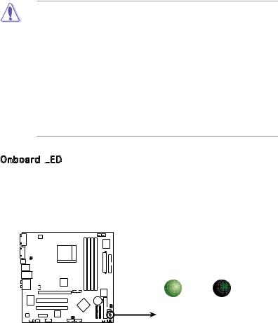
Onboard LED

The motherboard comes with a standby power LED. The green LED lights up to indicate that the system is ON, in sleep mode, or in soft-off mode. This is a reminder that you should shut down the system and unplug the power cable before removing or plugging in any motherboard component. The illustration below shows the location of the onboard LED.
M2R-FVM |
SB_PWR
ON |
OFF |
Standby |
Powered |
Power |
Off |
M2R-FVM Onboard LED
ASUS M2R-FVM |
1-5 |
1.5Motherboard overview
Before you install the motherboard, study the configuration of your chassis to ensure that the motherboard fits into it.
Make sure to unplug the power cord before installing or removing the motherboard. Failure to do so can cause you physical injury and damage motherboard components.
1.5.1Placement direction
When installing the motherboard, make sure that you place it into the chassis in the correct orientation. The edge with external ports goes to the rear part of the chassis as indicated in the image below.
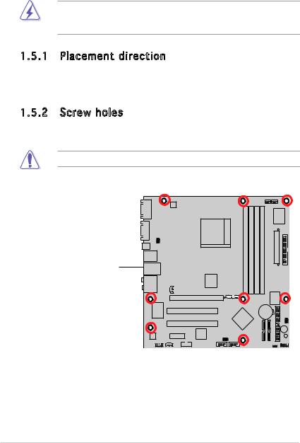
1.5.2Screw holes
Place nine (9) screws into the holes indicated by circles to secure the motherboard to the chassis.
Do not overtighten the screws! Doing so can damage the motherboard.
Place this side towards the rear of the chassis
M2R-FVM |
1-6 |
Chapter 1: Hardware information |

1.5.3Motherboard layout
|
|
|
|
|
24.5cm (9.6in) |
|
|
|
|
|
|
|
|
|
ATX12V1 |
|
|
|
|
|
|
|
|
|
|
COM1 |
|
|
|
|
|
|
|
|
|
CPU_FAN CHA_FAN1 |
|
|
|
|
|
|
|
|
|
|
|
I/O |
|
|
|
|
|
|
|
|
Socket AM2 |
(128bit,240-pin module) |
(128bit,240-pin module) |
(128bit,240-pin module) |
(128bit,240-pin module) |
Super |
|
|
VGA1 |
|
|
|
|
|
|
|
|||||
SPDIF_O2 |
USBPW12 |
|
|
|
ATXPWR1 |
|
|
|||||
USBPW34 |
|
|
|
|
|
|||||||
F_USB12 |
|
|
|
|
|
DIMM A1 |
DIMM B1 |
DIMM A2 |
DIMM B2 |
|
|
FLOPPY1 |
LAN_USB34 |
|
|
|
|
|
|
|
|||||
|
|
|
|
|
DDR2 |
DDR2 |
DDR2 |
DDR2 |
|
|
|
|
|
|
|
|
ATI RS485 |
|
|
|
|||||
AUDIO1 |
|
|
SPDIF OUT |
|
|
|
|
|
|
|
||
|
|
|
|
|
|
|
|
|
|
|
||
|
|
|
|
|
|
|
|
|
|
|
|
|
|
|
|
|
|
|
R |
|
|
|
4Mb |
|
|
|
|
|
|
PCIEX16 |
|
|
|
|
|
|
|
|
|
|
|
|
|
|
|
|
|
BIOS |
|
|
|
RTL8100C |
|
|
|
M2R-FVM |
|
|
|
|
|
|
S |
|
|
|
|
PCI1 |
|
|
|
|
CR2032 3V |
|
|
||
|
|
|
|
|
|
|
Lithium Cell |
|
R |
|||
|
|
|
|
|
|
|
|
CMOS Power |
|
PASSWORD BIOS |
||
|
|
|
|
|
ATI SB600 |
|
|
|
|
|
||
|
|
|
|
|
|
|
|
|
|
|
|
|
|
|
|
|
PCI2 |
|
|
|
|
SATA3 |
SATA1 |
|
|
|
|
|
|
|
|
|
|
|
BUZZ1 |
|||
|
|
|
|
|
|
|
|
|
|
|
||
|
|
|
PCIEX1 |
TSB43AB22A |
USBPW56 |
|
|
|
|
|
SB PWR |
|
ALC883 |
|
|
|
USBPW78 |
|
|
SATA4 |
SATA2 |
IDE1 |
|||
|
|
|
|
|
|
|
|
|
||||
F_AUDIO1 |
AUX1 |
IE1394_2 |
|
USB56 |
USB78 |
|
|
|
CLRTC |
F_PANEL1 |
||
ASUS M2R-FVM |
1-7 |
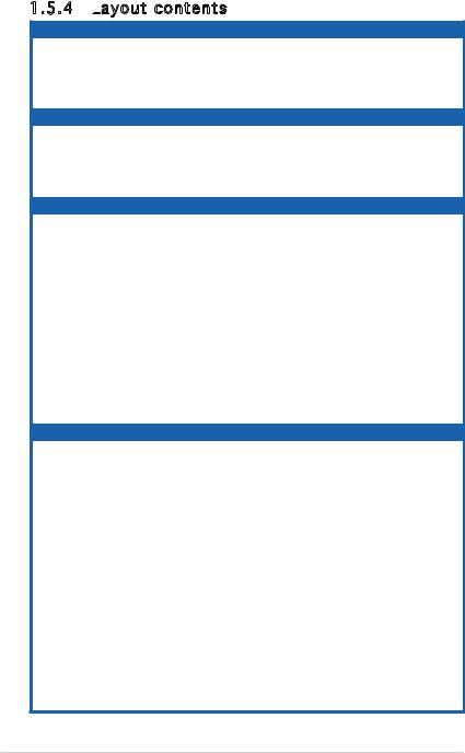
1.5.4Layout contents
|
Slots |
|
Page |
|
|
1. |
DDR2 DIMM slots |
1-15 |
|
|
2. |
PCI slots |
1-19 |
|
|
3. |
PCI Express x 1 slots |
1-20 |
|
|
4. |
PCI Express x16 slots |
1-20 |
|
|
Jumpers |
|
Page |
|
|
1. |
Clear RTC RAM (3-pin CLRTC1) |
1-21 |
|
|
2. |
USB Power (3-pin USBPW12, 34, 56, 78) |
1-23 |
|
|
3. |
Password Skip (3-pin PASSWORD_s) |
1-22 |
|
|
4. |
BIOS Recovery (3-pin BIOS_R) |
1-22 |
|
|
Rear panel connectors |
Page |
|
|
|
1. |
Serial (COM1) port |
1-25 |
|
|
2. |
VGAport |
1-25 |
|
|
3. |
S/PDIF Out port |
1-25 |
|
|
4. |
LAN (RJ-45) port. |
1-24 |
|
|
5. |
IEEE 1394a port. |
1-24 |
|
|
6. |
USB 2.0 ports 1 and 2, 3 and 4 |
1-25 |
|
|
7. |
Center/Subwoofer port (orange) |
1-24 |
|
|
8. |
Rear Speaker Out port (black) |
1-24 |
|
|
9. |
Line In port (light blue) |
1-24 |
|
|
10. |
Line Out port (lime) |
1-24 |
|
|
11. |
Microphone port (pink) |
1-24 |
|
|
12. |
Side Speaker Out port (grey) |
1-24 |
|
|
Internal connectors |
Page |
||
1. |
Floppy disk drive connector (34-1 pin FLOPPY) |
1-25 |
|
|
|
2. |
IDE connector (40-1 pin PRI_IDE) |
1-26 |
|
|
3. |
SerialATAconnectors (7-pin SATA1, SATA2, SATA3, SATA4) |
1-27 |
|
|
5. |
USB connectors (10-1 pin USB56, USB78) |
1-29 |
|
|
6. |
IEEE 1394a port connector (10-1 pin IE1394_2) |
1-30 |
|
|
7. |
CPU and chassis fan connectors |
1-28 |
|
|
|
(4-pin CPU_FAN, 4-pin CHA_FAN1) |
|
|
|
8. |
ATXpowerconnectors (24-pin EATXPWR, 4-pin EATX12V) |
1-28 |
|
|
9. |
Front panel audio connector (10-1 pin F_AUDIO1) |
1-30 |
|
|
10. |
Internal audio connector (4-pinAUX1) |
1-29 |
|
|
11. |
Digital audio connector (3-pin SPDIF_OUT) |
1-27 |
|
|
12. |
System panel connector (10-1 pin F_PANEL1) |
1-31 |
|
• System power LED (Green 2-pin PWR_LED)
• Hard disk drive activity LED (Red 2-pin HD_LED)
• ATX power button/soft-off button (Black 2-pin PWR_BTN)
• Reset button (Blue 2-pin RESET)
1-8 |
Chapter 1: Hardware information |
1.6Central Processing Unit (CPU)
The motherboard comes with a 940-pin AM2 socket designed for the AMD Athlon™ 64 X2/Athlon™ 64/Sempron™ processor.
The AM2 socket has a different pinout from the 940-pin socket designed for the AMD Opteron™ processor. Make sure you use a CPU is designed for the AM2 socket. The CPU fits in only one correct orientation. DO NOT force the CPU into the socket to prevent bending the connectors on the socket and damaging the CPU!
1.6.1Installing the CPU
To install a CPU:
1.Locate the CPU socket on the motherboard.
M2R-FVM |
M2R-FVM CPU Socket AM2
2.Unlock the socket by pressing the lever sideways, then lift it up to a 90º angle.
Socket lever

Make sure that the socket lever is lifted up to a 90º angle; otherwise, the CPU will not fit in completely.
ASUS M2R-FVM |
1-9 |
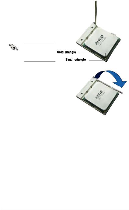
3.Position the CPU above the socket such that the CPU corner with the gold triangle matches the socket corner with a small triangle.
4.Carefully insert the CPU into the socket until it fits in place.
Please make sure your CPU is fully plugged-in to reduce abnormal symptom.
Gold triangle
Small
 triangle
5.When the CPU is in place, push down the socket lever to secure the CPU. The lever clicks on the side tab to indicate that it is locked.
6.Install a CPU heatsink and fan following the instructions that came with the heatsink package.
1-10 |
Chapter 1: Hardware information |
Loading...